Heating cable is widely used mainly for two things:
- in heated floors
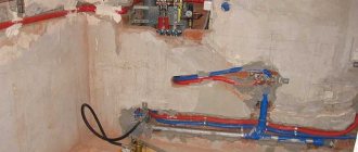
- for heating water pipes
At one “wonderful” moment, the heated floors stop heating, and the water pipes begin to freeze.
How to find out whether the cable itself is to blame or the reason is elsewhere (automation malfunction, poor contact)?
If you have a Chinese multimeter, and sometimes even without it, you can check this yourself without calling a specialist to your home.
The most important thing is to know where to “poke” the probes and what numbers on the screen will clearly indicate a malfunction or, conversely, the functionality of the cable.
Types of heating cable
Let's start with the fact that there are two types of heating cables:
- resistive (with constant resistance)
Most often they are used in heated floors.
- self-regulating (more suitable for heating water pipes and roof snow melting systems)
Their power “floats” depending on temperature. This is due to a change in the resistance of the semiconductor matrix, between which two cores are placed.
The method of checking both of them is basically the same, but the readings that will be displayed on the multimeter screen can differ significantly and mislead many.
Resistive heating cables generally have two working cores and a protective braid. However, single-core specimens are also found.
They have one working core, and the end of the cable, after laying it on the floor, has to be brought to the beginning of the loop so that it can be fully supplied with phase and zero. For such varieties, all measurements are taken between the beginning and end of the loop.
When should you check?
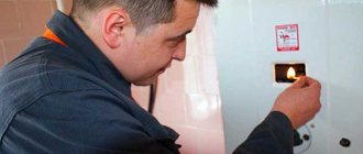
The need to check the heated floor system may arise in another situation. If the floor does not heat up, you should first make sure that the thermostat is not supplying electricity. In this case, the corresponding indicator on the front panel should light up. If there is power, check the temperature setting. Perhaps the regulator is simply disabled. If the settings are correct, check further if:
- There is no heating over the entire floor surface. If the machine suddenly turns off, you can safely talk about a short circuit. In such a situation, a system check is inevitable. Until it is completely completed, it is unsafe to operate the equipment. To identify the damaged section of the cable, turn off the voltage. The power wires are disconnected from the thermostat and the area between the regulator and the panel is connected. The damaged area is located in the area where the multimeter shows a zero value. The search continues until the damaged section is found. If the goal is not achieved, the heating cable is disconnected from the thermostat and its input resistance begins to be measured. If there is a short circuit in this place, we can say that the regulator has failed: it will have to be replaced. If there is no short circuit, you will have to measure the resistance of the wires. If infinity appears on the device screen, there is a break inside the cable;
- The system temperature cannot be adjusted. In this case, the heating remains, but it is not possible to change the readings. A failure indicates a temperature sensor output or incorrect operation of the regulator. In the latter case, the device will have to be replaced with a new one. If the reason is the temperature sensor, it should be disconnected from the thermostat to check the resistance value. It must fully comply with what is specified in the accompanying documents. If there are deviations, the floor covering is raised and the sensor is replaced with a new one;
- The floor surface is heated fragmentarily. A thermal imager or numerical determination of the amount of power consumption will help to establish heating zones. If its value is slightly less than declared, it means that the heated floor is not working correctly due to a break in the heating cable. When the design value is exceeded, a short circuit occurs between individual elements. As a result, some part of the heating circuit remains unused. The other consumes more than originally planned.
How to test a resistive cable?
So, what and how should you check? Let's start with the resistive option.
First of all, check the resistance between the two working wires, to which voltage is applied.
If the cable is connected to a thermostat built into a socket box, you will have to pull it out of the wall and disconnect the wires from the terminal blocks.
First turn off the power supply in the electrical panel and check on site for the absence of voltage.
For those who have the cable connected directly to the plug (there are such ready-made kits), just pull the plug out of the socket and then take all measurements between the two pins of the plug. But this primarily applies to self-regs; more about them below.
For measurements we will need a regular Chinese multimeter. Place its switch in the “resistance measurement” position (for resistive ones, a division of 200 Ohms is usually enough), and plug the probes into these connectors.
By the way, before work it would be a good idea to check the tester itself and not make stupid mistakes when measuring. Read at your leisure what they lead to.
In general, touch the cores with probes and look at the readings on the display. What should we focus on here and what should we compare them with?
Firstly, the value should not be equal to infinity (the number one on the left side of the scoreboard).
Or OL (Over Load).
If necessary, switch the multimeter to a larger scale - 2000 Ohms. If there are identical readings, this indicates that your cable is faulty and one of its wires is broken somewhere.
Thermal sensor malfunction
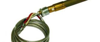
In order not to open the screed ahead of time, check the serviceability of the temperature sensor. Its cable is a two-core wire.
- the multimeter is switched to ohmmeter mode,
- parameters are set,
- the resistance value is measured.
Before checking, turn off the power supply
- Turn off the power to the electrical network of the apartment or house (unscrew the plugs on the electrical panel).
- Connect the power wires directly to the panel, bypassing the thermostat: contact No. 1 to contact No. 3, and contact No. 2 to contact No. 4.
- Turn on the electricity supply and wait half an hour for the floor to heat up.
How to find a break in a cable with a multimeter?
For a resistive heating cable, such a break in 90% of cases is observed at one of the couplings:
- at the initial
Where it is spliced with the power cable.
- or at the end
How to find out which clutch is at fault? To do this, you will need a multimeter with a capacitance measurement function.
Moreover, the accuracy of measurements and specific numbers do not matter. It is important by what order of magnitude they differ from each other.
Attach one probe to the working core and the other to the braid. Then to another core and again to the braid.
If the measurement values on one core differ several times from the values on the other, then there is a break in the initial coupling.
If the indicators are approximately equal, then there is a break at the end coupling.
Check the readings with an ohmmeter or multimeter:
- Between black and white wires: see factory settings. Typically, when selecting a 200 ohm scale, the reading should be between 20 and 200 ohms. If there are no readings, this confirms a cable break. Before jumping to conclusions, double check the batteries on your meter and take the measurement again. Use a digital ohmmeter (with a digital display) rather than an analog one (with a dial indicator).
- Between black wire and ground: No reading should be displayed. If there is a reading, then there is a “ground fault”, that is, a “short circuit”. The OTDR should show the distance to the fault on that wire and indicate "Short".
- Between white wire and ground: No reading should be displayed. If there is a reading, then there is a “ground fault”, that is, a “short circuit”. The OTDR should show the distance to the fault on that wire and indicate "Short".
What resistance should there be?
Let's return to the original measurements. The resistance between the cores, in addition to infinity, should also not be zero.
In this case, we are talking about a short circuit between them.
In normal condition, on a working cable with a length from 20m to 80m (these sizes are mainly used in ordinary homes), the resistance is several tens of ohms.
Or a maximum of more than a hundred ohms.
Everything directly depends on the length and brand. Resistance data is always indicated on the product label.
It is with these parameters that you should make comparisons. Differences can be no more than 10% upward and no more than 5% downward.
Therefore, after installing the heating, never throw away this piece of paper; you may still need it.
As a last resort, take a photo of it with your smartphone.
In a good way, if some company installs your heating, then before commissioning they must carry out all measurements, record the obtained data in a separate test report and transfer it to you.
If you don’t have such a piece of paper and no protocols, at least find out the brand and approximate length of your heating cable. It will be possible to find all the technical specifications on the Internet and make appropriate comparisons based on them.
Here is data on some popular brands of heating cables that are widely used in our country.
Heated floor with resistive cable from Rexant
Heating cable from Devi
Heating cable from Nexans
Heating cable from Lavita
Look at the “resistance” parameter. For resistive models, it is strictly tied to the cable length.
Estimate how many meters are laid on your site and compare the results on the multimeter display with the tabular figures.
Thermostat repair
It's no secret that sometimes thermostats fail, and at the most inopportune moment. There are several reasons for this sad event. The most common is incorrect installation: an error in the connection diagram (such as mixing up wires and terminals, too much load), painting the installed thermostat, installing the thermostat in a damp room. With such errors, the thermostat either immediately fails or its service life is significantly reduced. Trust the installation of the thermostat only to a professional electrician.
The second reason is related to the design features of thermostats. The fact is that basically their power supplies are built according to a transformerless circuit with a ballast capacitor (almost all regulators from such companies as: OJ Electronics, Eberle, Raychem, some DEVI), or according to a key stabilizer circuit such as, for example, Devireg D530, Devireg D535 , Veria B45, Veria T45.
Such thermostats are sensitive to impulse noise in the power supply network, which occurs when devices such as a welding transformer, hammer drill or electric lawn mower are turned on near the controller, which often happens in country houses. In such conditions, it is better to use regulators with transformer power supplies that do not allow impulse noise to pass through (for example, the Busch Jaeger NTC100 regulator).
If your regulator fails, do not rush to throw it away. In most cases, the regulator can be repaired.
Our company provides warranty repairs of thermostats purchased through our network of stores or through our dealers, as well as non-warranty repairs of any regulators.
The cost of such repairs is fixed - 1000 rubles.
Warm floor doesn't work! What to do?
A typical customer case! You have decided to install a heated floor in your home, and the builders who are doing the renovations say, “They have been laying floors since early childhood. More than 1000 heated floors have already been installed and everyone is happy. What should I put there?” You, as a person who sincerely trusts your builders, are afraid to show doubts about their professionalism and entrust them with the work of installing heated floors. From this moment the headache begins! The builders finished the repairs and left for their homeland. The old tiles have been laid, the cold weather has set in, but the warm floor is not working! Let's start looking for the cause of the problem.
Resistance measurement of self-regulating cables
But all this is true only for resistive brands. For self-regs, tabular data on resistance strictly tied to its length cannot be found.
For them, it depends on what temperature at one time or another you will measure the cable. This is, in fact, the principle of their work.
The warmer it is, the less watts it consumes, and therefore its resistance changes.
Therefore, before taking measurements you will have to find out the temperature of the floor or pipe. This can be done using a pyrometer.
A self-regulating cable in a cold state has low resistance and high inrush currents. You will have to calculate it yourself and compare it with the values on the device display.
How to do it? Technical specifications will be needed again. You just need to look at the power data and the graph of its dependence on temperature.
These are the parameters for self-regulating cables of the most popular brands.
Self-regis from Raychem
Rexant
Ensto
Lavita
Devi
Nexans
Common problems with heated floors
The reason for the breakdown of the heated floor may be improper installation of equipment, or failure of individual elements of the system.
Thermostat
As mentioned above, it is responsible for maintaining the floor temperature in a given range. It is also a switching link on which all underfloor heating circuits are assembled (power, load, temperature control).
And if all connections are made according to the diagram, then the reason for the malfunction of the thermostat lies in its elemental base. Of course, you can try to restore the specified block. But as practice shows, most often repairing a thermostat comes down to replacing it.
temperature sensor
It is an easily replaceable element due to the fact that it is located in a corrugation (laid in the floor screed). The durability of this element directly depends on the quality of the materials from which it is made, as well as on the correct location of it relative to the heating cable (see the manufacturer’s recommendations).
Heating cable
A fairly reliable element of the system, which most often fails due to improper installation. Moreover, the most “problematic area” of the heating cable is the coupling (through which the power is supplied)
Therefore, when doing self-repair, you should first pay attention to this particular unit.
By the way, the method for choosing a heating cable for a heated floor can be found here.
Resistance calculation example
Let's look at how such a calculation is made. Let's say we have as a test sample a cable of the SRL-16-2 brand, with a power of 16 W/m.
The total length of the site is 10 meters. The temperature of the pipe on which the cable is laid is currently about 5 degrees.
First, let's calculate how much current this self-regulator should consume under such conditions.
(P-power per 1m, L-cable length, U-voltage)
We take power based on the dependence graph. In our situation for 5C it turns out to be approximately 17.5 W/m
Error
Please note that the real voltage must be measured, and not the conventional 220V.
Sometimes it can differ significantly both up and down. Take standard 220V and you will get a significant error that distorts all the data.
I=P*L/U=17.5W*10m/235V=0.74A
Voltage measurements are carried out with the same multimeter. After calculating the current, we calculate the cable resistance.
That is, it turns out that our multimeter, under given “climatic” conditions, should show a resistance within 320 Ohms. This is the calculation:
R=P*L/I2=17.5W*10/0.74A*0.74A=319.5 Ohm
And this is the result:
If its readings differ tenfold, up or down, then something is wrong with the heating cable.
This approach is very conditional and in many respects everything will depend on the temperature of the self-regulating matrix. It is the temperature error that introduces the largest inaccuracies.
It is quite likely that the beginning of the cable will have one temperature, and its end on the frozen pipe at the end of the house will be completely different. In this case, you should not rely 100% on such calculations.
However, again, you can find out at least an approximate order of magnitude.
If the multimeter shows data of several tens or hundreds of kOhms, and the calculated data indicates tens or hundreds of Ohms, then there is clearly something wrong with the cable.
All measurements on self-registers are most often carried out on a multimeter scale of 2000 Ohms, not 200 Ohms.
What in the end...
Most elements of a heated floor are forever hidden under a decorative coating. To be sure of the long-term operation of the equipment, it is necessary to conduct preliminary testing upon purchase and immediately after installation. And in case of complete or partial failure, have a multimeter on hand. With its help, you can always ring the system and identify the area with a short circuit.
Question
Write in the comments what you think - is it worth using heated floors as the main source of heating at home? Usually it is used in the form of additional insulation of individual rooms. Indeed, in the event of a system failure, dismantling the coating and repairing it will cost a pretty penny...
Checking the insulation resistance of the shell
The second test is to measure the insulation resistance. A metal shell is already involved here.
By the way, some cables come without it. You can’t check anything with them in this regard; you’ll have to ring the wires directly onto the pipe.
This test is carried out not only when there are doubts about the serviceability of the heating, but also:
- before installation and cable laying
- after installation of thermal insulation
- before first commissioning
- periodically during system maintenance and audit
The main testing device here is already a megger, and not a Chinese tester.
Using a multimeter you can only detect a clear 100% short circuit between the cores and the sheath. When they physically come into contact with the copper braid in some place and short-circuit to it.
If the outer insulation is cut, mechanically destroyed, the cable absorbs a lot of moisture, but there is no contact with any of the wires, the multimeter will not show anything (megaohmmeter sometimes too, more on that below).
How to carry out this check? The order here is as follows:
- turn off the 220V power supply
- disconnect all cable cores and braid from the thermostat or terminal block to which they are connected
Next you start taking measurements. First you need to check with a multimeter for the presence of an obvious short circuit.
Breakdown options
If there is unevenness or lack of heating in the electric floor heating system, there are not many reasons for the breakdown.
Don’t panic, if during installation all the parameters for proper installation were followed, then most likely it won’t be difficult to get rid of the problem.
It is necessary to check the power supply to the system, the serviceability of the sensor and the integrity of the load cable system.
The simplest reasons for the lack of heating are failures in the settings or a breakdown of the thermostat.
| № | Possible reasons | What to do |
| 1 | No electricity in the network | Make sure the thermostat is working properly: the indicator light should be on |
| 2 | Settings are lost or changed | Check and restore settings |
| 3 | No mains voltage | Measure the voltage in the network by disconnecting the thermostat and connecting the device to terminals L and N; the value should be 220 V. |
Checking insulation with a multimeter
In 99% of cases, ordinary users do not have a megohmmeter. Therefore, such a test in certain situations can at least show something.
Set the switch wheel to the maximum division (2000 kOhm).
Connect one of the probes to the working core, the other to the braid or yellow-green core. If there is damage and a short circuit on the heating cable, the readings will be zero or only a few ohms.
The same test can be carried out in the “call” mode. If there is a short circuit, the multimeter will beep.
During such a test, a working, serviceable cable should show the value “infinity” (the number “1” in the left field of the display or the inscription OL).
If at least some numbers are displayed on the display, then this is a reason to seriously think about the further operation of the cable. With such insulation under mains voltage, there will definitely be a current leakage on it.
Think for yourself, if some battery in a tester with a constant voltage of max 9V is capable of what is called “breaking through” the insulation and showing such a result, then what will happen with a change of 220V?
When the heating is connected through an RCD (as required by the rules), then the RCD should definitely turn off and work.
After checking one working core, do the same procedure with the second. To save time, you can initially hook two at once.
How can I replace the temperature sensor?
The temperature sensor used in thermostats for heated floors is a thermistor with a negative TCR (temperature coefficient of electrical resistance). This means that when heated, the resistance of the sensor decreases.
The second parameter required to select a temperature sensor is the resistance value under normal conditions, at 20°. The resistor value is usually indicated on the thermostat body next to the temperature sensor connection terminals or in the product data sheet.
To select a temperature sensor, this data is quite sufficient. The only thing that is difficult to find out and select is the TKS characteristic, that is, the change in the resistance value of the temperature sensor due to changes in ambient temperature.
But this is not a critical parameter; anyway, the temperature on the thermostat is set experimentally. After all, the temperature sensor is installed in the floor and the set temperature on the thermostat sets the floor heating temperature, and not the room temperature.
How to determine the resistance of a temperature sensor
The temperature sensor of the SPYHEAT ETL-308B thermostat has failed. Its technical characteristics were unknown. They had to be determined experimentally.
To do this, external circuits were connected to the thermostat, in accordance with the diagram printed on its body - supply voltage was applied, an incandescent light bulb was connected instead of heating elements, and a variable resistance was connected instead of a temperature sensor.
I had a resistance magazine available, so I decided to use it for calibration. The resistance magazine is a box in which high-precision resistances are placed and there are switches with which you can set the desired value.
Consistently setting the regulator knob to positions from 20° to 30° and changing the resistance value with the knobs in the resistance magazine until the thermostat operates, I built a sign.
Dependence of the thermostat response on the resistance value of the temperature sensor
| Temperature set on the thermostat, °C | Turn-on resistance, kOhm | Turn-off resistance, kOhm |
| 20 | 16 | 14 |
| 25 | 10 | 12 |
| 30 | 8 | 9 |
| 35 | 6 | 7 |
Don't miss: Balancing the heating system, adjusting heating radiators
Based on the data in the table, for this heated floor thermostat, a thermistor with a negative TCR of 10 kOhm is suitable as a temperature sensor. The resistance value of the resistor when turning the light bulb on and off turned out to be different due to hysteresis in the thermostat itself. This is necessary so that the heating element of the warm floor turns on less often.
Determining the temperature sensor rating can also be done using a 47 kOhm variable resistor. You just have to disconnect the thermostat from the network every time after turning the light bulb on and off and measure the resistor resistance with a multimeter.
You can do without measurements. It is enough to have several constant resistors with values ranging from 10, 15, 20 and 30 kOhm. Resistors are connected in turn instead of the temperature sensor. By rotating the thermostat knob, you need to determine which resistor the light bulb will turn off and on at a temperature of about 20°C.
Thermistor selection
You could buy it ready-made, but to do this you had to place an order online and wait for delivery. In addition, the price of the issue reached 20% of the cost of the thermostat itself.
Therefore, it was decided to make a temperature sensor from available thermistors. There was a thermistor with a nominal value of 10 kOhm with a negative negative TKS type MMT-4. I decided to use it for repairs.
For connection there was a piece of wire with which the failed temperature sensor was connected. In principle, any wire can be used to connect the sensor, as long as it can withstand a temperature of at least 100°C. To check, the ends of the wires were stripped and wound onto the thermal resistance terminals.
Next, the thermistor was located in close proximity to the incandescent light bulb connected to the terminals for connecting the heating element of the heated floor. Supply voltage was applied to the thermostat.
After a few minutes, the light bulb heated the thermistor, its resistance decreased, and the thermostat turned off the voltage supply to the light bulb. When the thermistor cooled down, the light came on again, and this continued ad infinitum with a period of several minutes.
After checking the operation of the heated floor thermostat, wires were soldered to the MMT-4 thermistor with soft solder and pieces of insulating tube were put on the soldering points.
For reliability, you can put a heat-shrinkable insulating tube on the thermistor. A homemade temperature sensor was installed during the installation of a heated floor and showed stable operation.
As you can see, even without experience in repairing electrical appliances, you can repair a thermostat for a heated floor with your own hands at home, including making a temperature sensor from a standard thermistor.
Attention, the electrical circuits of thermostats are galvanically connected to the phase of the electrical network. Touching exposed parts of a circuit connected to an electrical outlet may result in electric shock.
Checking the heating cable with a megger
Megger measurements are carried out according to the same scheme. One probe is the working core, the other is the braid.
What data indicates that your cable is working properly or, on the contrary, is damaged and requires repair?
When the test voltage is applied for 1 minute, the insulation resistance on the heating cable must be at least 100 mOhm.
Here is an extract from the instructions of one of the leading manufacturers of these products, Raychem.
Such tests must be carried out at voltages of 500V, 1000V and 2500V.
The recommended test voltage for heating cables is exactly 2500V.
Here is a clear example of testing the same cable with several! insulation cuts. This is when a voltage of 1000V is applied to it (data in GigaOhms!).
But this is already 2500V. The difference is what is said on the board (data in MegaOhms).
After testing the cores, the same procedure must be repeated between the metal braid and the heated pipe.
The readings between these two tests (core-braid and braid-pipe) should not differ by more than 25% at all voltage levels (500-1000-2500V).
Error
Some experts argue that the heating cable can be damaged by such a high voltage, and more than 500V cannot be applied to it.
Yes, this applies primarily to mineral insulated (MI) cables. Here is an extract from the instructions of the same Raychem on this matter.
True, even there we are not talking about 500V, but a maximum of 1000V.
And the parameters of the minimum insulation resistance in megohms are already different (at least 20 mOhm, not 100 mOhm).
Real values for good cables are usually more than 10 ohms. Here are several measurements of different brands of cables made by Woks Warm Floor specialists.
The lower the insulation resistance of the heating cores, the shorter the service life of the heating cable in real conditions or in case of local overheating.
High-quality samples can easily withstand constant voltage even at 5000V. Before laying and installation, this clearly reveals all hidden manufacturing defects (thin areas or microcracks and micropunctures).
At the same time, many people confuse non-destructive tests (constant voltage from a megger) with acceptance tests, which are carried out on heating cables in accordance with GOST R IEC 60800-2012.
You can check them out at the link above. In whatever ways they do not mock test samples before they go on sale.
Error
Do not touch any wires with your hands when measuring with a megger.
Firstly, this is prohibited due to safety precautions. Secondly, by doing so you introduce an error and underestimate the measured resistance.
Determine the side with a cliff
Using an ohmmeter, determine which side (towards the thermostat or towards the end of the mat) the break is relative to your cut. Twist the black and white wires together on the thermostat using a jumper clamp (do not connect the ground wire). Check the resistance from the cut to the thermostat. The readings should appear (a fraction of the factory value, since not the entire cable is measured), and there should be no ground fault. If this is not the case, then the tear is on that side and the OTDR should be reused as described above to determine the distance of the tear from the cut site. If the original drawing and estimate were done correctly, you should be quite close and the distance reading in meters should be small.
If everything is fine with this chain, go to the other side of the cut and use an ohmmeter to measure towards the end of the mat. If the readings obtained do not correspond to the complete circuit, reuse the OTDR as described above to get closer to the break location.
How to properly install underfloor heating
If you have chosen a “warm floor” heating installation with a type of cable heating elements, then first you need to calculate the installation step of the electric heated floor. The following formula is used for this:
H = S × 100 / L,
here: H is the laying step in centimeters;
S is the surface area that will be used for installation;
L is the length of the heating wire.
Installation of floor heating
The length of the electrical cable depends on the power needed to heat the room.
Having decided how much of this electrical wire is needed and how much area will be covered by the heating system, you can begin installation.
The laying technology consists of several stages. First, you will need to make small recesses in the surface of the base to accommodate the temperature sensor, as well as the location of the wires to connect the thermostat.
To improve the contact of the base with the poured concrete screed, the dry and cleaned surface should be coated with a deep penetration primer.
The prepared base must be covered with roofing felt or polyethylene film, and some heat-insulating fiber of the required thickness with a protective film must be laid on top. It is necessary to protect the thermal insulation material from the influence of alkaline components of the concrete mixture.
To do this, use mounting tape, laying it in accordance with the calculated step size. To securely connect it to the base, dowels or other devices are chosen.
How to lay film floors under laminate
How to properly lay laminate flooring with your own hands
Most often, film floors are laid under laminate.
The algorithm of actions is similar to that which should be performed when laying cables:
- forgive isolon,
- the joints are taped;
- nail a damper tape around the perimeter;
- The underfloor heating strips are cut into the required lengths and placed on top of the insulation.
- a silver or copper bus runs along the edges of the film; at the cut site it must be insulated with a bitumen adhesive plate;
- The contacts of the supply metal wires are connected to the busbars and crimped with pliers.
All contacts must be covered with bitumen sticky insulator. All protruding parts of the contacts are hidden in cut-out recesses in the heat insulator.
A temperature sensor is installed and also hidden in a cut-out recess in the isolon. In order to cut recesses in the heat insulator, use a regular knife.
This entire procedure must be done carefully and diligently, without leaving exposed wires.
The heating film is covered with plastic film on top. You can lay laminate flooring.
Important. When laying laminate on a heating film, no foamed polyethylene layer is required
If, instead of laminate, you need to lay linoleum or carpet on top, then you need to lay 1 cm thick plywood on top of the film. It is not recommended to use thick plywood, so as not to waste extra energy on heating it.
Connection diagrams in apartments
What is the way out of the situation?
In city apartments, you can connect water heated floors according to several proposed schemes:
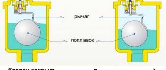
- Scheme A using a two-way valve connected to a thermostat. It regulates the flow of water. You can also install balancing valves. In this way, the temperature level will be regulated by just pressure. In this case, the pressure is controlled by the bypass valve.
- Scheme B involves the use of a bypass, which is a jumper between the combs. Here you can do without a bypass valve.
- Scheme B provides for the installation of a three-way valve on the return line. It will redirect the cooled water to the supply, leveling the desired temperature. The simplest but reliable scheme.
- Scheme D is the same as B, only a three-way valve is placed at the input. It dilutes the hot water with cooled water from the return before heading to the circulation pump.
- Scheme D. A four-way mixing valve is needed here. Can be installed with either manual or automated control.
- Scheme E. One of the most complex and expensive, since it is necessary to purchase a pressure gauge, an air vent and a valve that will regulate the pressure. But that's not all. A membrane expansion tank is needed to compensate for water hammer. In addition, the coolant is fed using a block equipped with a filter, check valve and valve.