The situation is as follows. The boiler only works when the button is pressed. In many cases, everyone immediately thinks that the solenoid valve is faulty. Or worse. It happens that it is not immediately clear what is going on, and there is a great desire to immediately change the entire automation unit as a whole. The most annoying thing is that the main cause of the malfunction may not be affected or eliminated. And after replacing the automation unit, everything will remain as it was. Therefore, please, until you figure out what’s going on, until you see real evidence, do not make hasty decisions regarding replacing the block .
The situation in this case is that the boiler works “directly”, so to speak, bypassing all protections. This is unacceptable, although it is very common in everyday practice. Some people don’t even suspect that gas enters the boiler bypassing the protection against extinguishing the igniter, so to speak, directly into the boiler.
When the solenoid valve button does not lock, there are only three faults.
1. Thermocouple malfunction. The thermocouple is either burnt out or there is poor contact between the thermocouple and the solenoid valve.
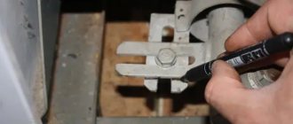
First, let's check the thermocouple. Unscrew the thermocouple connection nut. We leave its tip in the working igniter (the boiler is working?!) and take the tester. One probe is on the thermocouple body, the other is on the contact at the end of the thermocouple.
When heated, the thermocouple generates an EMF, which should keep the valve button pressed. If the EMF is less than 20 mV, then the thermocouple definitely needs to be replaced. And you need “Instructions for replacing the thermocouple”.
2. Solenoid valve malfunction. Electromagnetic valves behave differently, but for the most part they are reliable, low-current and rather primitive devices, inside of which there is an ordinary winding. There is current, the magnet magnetizes, there is no current and there is no magnet. Boxes usually become obsolete after years have passed. There are also cases when they try to tighten the nut of a thermocouple or thermoplate as tightly as possible (and here you just need a regular electrical contact). They pull so that they tear off the winding wires inside the box from the outgoing contacts. You can try measuring the resistance of the solenoid valve, but usually no one does this. The solenoid valve is usually the last to be changed in the chain of spare parts listed here . Or it simply changes on its own when the boiler has been operating for more than 10-15 years. Or, if the boiler is located far away geographically, we take the valve with us in order to eliminate the problem in any way and for sure . If you decide to replace the Solenoid Valve, you will definitely need the “Instructions for replacing the Solenoid Valve” to carry out this process.
3. Malfunctions related to the operation of the thermal plate (poor traction)
The problems associated with the operation of this device have long been known. The very place where the thermal plate is located is exposed to both air and condensation. Ordinary rust, oxidation, poor contact, souring sometimes even causes hatred towards this device. The plant even produced a special control nut to detect problems associated with the operation of the thermal plate. By throwing the control nut onto the right contact of the Solenoid valve, you immediately bypass the thermal plate and understand whether it is it or not. The fact is that while the right contact of the electromagnetic valve is open (and should be normally closed), we will not understand at all what is wrong with the boiler. If there is no nut at hand, we close the right contact of the valve to the body, for example, using foil. If everything works right away, we deal with the thermal plate: clean it, adjust it, etc. In order to get serious about the thermoplate, it would be nice to get “Complete information on the operation of the thermoplate (poor traction).”
Here were presented all three of the most frequently repeated faults that “prevent the solenoid valve button from remaining in the pressed position.”
It is difficult to say right away what exactly is faulty.
1. All cases come down to checking the contact of the thermocouple with the solenoid valve and the contact of the thermoplate, which should be normally closed .
2. If the contact is tight, then check the thermocouple . If the thermocouple produces less than 16 mV, we change the thermocouple.
3. If it does not work with a working thermocouple, put a control nut on the second contact of the valve (or wind foil to close the contact to the body) to eliminate the electromagnet-thermoplate circuit.
5. If it still doesn’t work, change the solenoid valve.
6. If it doesn’t work when everything has been changed, we check it again in a circle.
7. Take your time. All this rubbish comes only from these three elements or from their incorrect interaction. We don't give up!
Thermocouple
This device is one of the few that can measure high temperature. It is both simple and yet reliable. A thermocouple is made of two wires of different metals that are connected at different points. All this makes it possible to use it for different purposes. The main disadvantage is the error of one degree. To ordinary people this seems insignificant. But for such devices, many consider such indicators to be simply gigantic.
The device is used as a fuse. It measures the temperature in the heating pad. If it starts to fall quickly (say, for some reason the fire goes out or there are problems with the smoke exhaust), the system is triggered, which sends a signal to the solenoid valve and the gas supply stops. Therefore, if this component does not work, the equipment is inoperative.
Sequence of actions for checking:
- The thermocouple has two ends, the first of which is heated by the igniter, and the second is attached to the solenoid valve. It is necessary to separate the device from the boiler, be it a regular one or a condensing one with a three-way valve.
- Then provide a constant flame. A candle is best.
- Heat the tip above the flame at a distance of 1 cm. Just be careful, as the heat can reach half of the body.
- We take the tester and turn it on to millivolts. One probe is placed on the body, and the second on the output contact.
- After half a minute, a working thermocouple will show the EMF in the range from 17 to 25 mV. If the indicators are normal, then the problem of a non-working system may be elsewhere.
DIY connection and installation
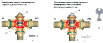
When connecting, take into account the direction of the coolant; there should be an arrow-shaped indicator at the top of the case.
The valve is installed in a vertical or horizontal direction; its location does not matter:
- In multi-storey buildings, the working fluid is supplied to the tap through the heating element, then to the pump and into the heating system. The input is designated “A”, the output – “AB”.
- Next, the supply of cooled water enters the boiler at the valve assembly at inlet “B”. To ensure that the pressure in the boilers is stable and a certain temperature is maintained, the individual characteristics of the boiler are taken into account; the installation of the device in a particular case may differ.
- The units are installed depending on the variations in their connections with other parts of the pipeline. Typically a valve is installed with a threaded connection.
Step by step installation guide:
During installation, it is important to avoid mistakes, which could damage the pipeline or set the temperature to sudden changes. The factory product must have arrows marked by which you can determine the direction of the moving flow and install the device yourself. When welding, do not allow the crane to overheat
The installation location must be easily accessible.
When installing a faucet in a coolant containing impurities, additional filters will be required.
Decide on the valve connection location depending on the direction of coolant flow.
Install the valve vertically or horizontally.
Install the lever at an angle within a radius of 90 to 180 degrees. The valve serves to mix cold and hot flows, prevents cold flow from entering the pipeline, otherwise condensation will form, the system will be deformed, cracks will appear at the joints, or become completely unusable
The valve serves to mix cold and hot flows, prevents the cold flow from entering the pipeline, otherwise condensation will form, the system will be deformed, cracks will appear at the joints, or become completely unusable.
Thanks to the mixing tap, the liquid at the entrance to the boiler will be at least 50 g, which eliminates sudden temperature changes; cold water does not have a negative effect on the pipes.
The task of the mixing valve is to prevent coolant from entering the pipeline at high temperatures. Average range -75 – 85 degrees.
Solenoid valve
The solenoid valve is a shut-off valve that directly affects the safety of the unit. It is mainly installed so that in the event of a problem, it closes the fuel supply. Emergency situations in the operation of gas heating can occur due to various factors:
- drop in fuel pressure;
- lack of fluid in the system (you can check the joints, three-way valve and pipes);
- worsening traction;
- gas leak.
Each of the problems described above is dangerous to human life, and therefore further operation of the system is unacceptable. This is why the solenoid valve is activated. Its initial position is open. To close it, an electrical impulse is applied to it, coming from a thermocouple installed above the flame in the combustion chamber or on the chimney.
It must be said right away that this element rarely fails, since it has great potential for use. Despite this, moments still happen.
There are two ways to check the functionality of this valve:
- Fire. The used thermocouple is replaced with a new one. The automatic button turns on. Next, the igniter is ignited and the fire is brought to the end of the thermocouple. In this case, the automation should work.
- Instrumental. The sensor is removed from the housing and a repair contact is inserted. It is supplied with voltage from 3 to 6V. If the solenoid valve is in order, the automation will work. Otherwise, you need to replace this element.
Features of Navien boilers
There are several other reasons why more than a million wall-mounted boilers of this brand have already been purchased in Russia. The product is perfectly adapted to Russian realities: it is highly resistant to low temperatures and other aggressive environments. Protected from network voltage sags. It is possible to connect boilers in a cascade chain. Elegant shape, design that fits into any Russian interior. The boilers come with a 36 month warranty. The manufacturer has established the supply of spare parts for service centers in the Russian Federation to eliminate breakdowns. Navien boilers are highly reliable; it is very difficult to permanently break the boiler. The boilers have an intelligent problem detection system built into the boiler system; using the error number, it is possible to determine what is broken in the boiler.
Ignition transformer
This element supplies the burner with a current discharge (spark), which is necessary to ignite the fuel. In addition to other elements that directly affect the operation of the unit, the component can also fail. As a result, all automation will work, but fire will not appear, since there is no source of ignition.
How can you quickly check the ignition transformer of a gas boiler for functionality? Just. You need to make a few simple movements:
- Through a special window, see whether the discharge is going on or not.
- Using a tester, check the voltage coming out of the controller during the ignition attempt. A figure falling within the range from 187 to 235V is considered normal.
- If a problem is detected, you need to disconnect the power from the transformer and connect it back.
- Check again.
Any gas boiler is equipped with many safety elements and sensors that allow you to monitor the correct operation of the unit. In the event of situations that clearly threaten human life, the system completely shuts down the installation.
In case of any breakdown, most owners of a gas water heater call a specialized service technician. However, services usually come with financial costs, right?
Scope of application
Household and industrial devices
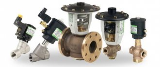
The standard solenoid gas valve has a wide range of applications and can be used in all areas where there is a need to control remote flows of liquids and gases. This list includes heating systems, water treatment and water supply, irrigation and sewerage systems, household appliances, and pipeline transport. The device is rarely used for vehicles, but its relevance is increasing in other industries.
Gas water heater valve device
In order to make it easier for home craftsmen to restore the functionality of a gas boiler, in particular when there is a malfunction of the gas valve, we will consider the design of the unit and the technical nuances of diagnostics and repair.
But, if you do not have experience in disassembling geysers and relevant knowledge on the topic, then it is preferable to invite a specialist for repairs and maintenance.
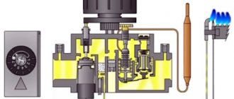
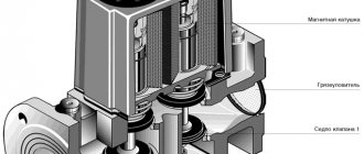
A device called a gas solenoid valve performs an important function of a gas water heater - controlling the flow of the fuel component (natural gas). The picture below shows a common version of the design of the control unit, which includes the valve.
In fact, the control unit is a two-stage mechanism, the first stage of which is the gas solenoid valve (1). The second stage is a mechanical device that provides adjustment via a manual control rod (2).
The design of the gas valve is quite simple - it is made on the principle of an electromagnetic traction device, which are used as part of a wide variety of devices and instruments. If you dismantle this component from the control unit diagram, for which it is enough to unscrew a couple of screws, the valve part, which is attached to a spring-loaded metal rod, will appear before the eyes of the master.
As you can see from the picture, the design consists of a skirt body , which includes a valve part - a membrane and an electromagnetic module . The valve part is mounted on a metal rod , spring-loaded for the return stroke to the “closed” position.
When voltage is applied to the electromagnet coil, the metal rod moves upward under magnetic influence and moves the membrane away from the passage hole of the skirt. This opens the gas passage towards the manual valve and further to the burner.
Manufacturers
Let's look at the most popular companies that produce gas valves.
Dungs
A German company that is one of the most popular in the production of gas control valves.
Dungs products began appearing on the Russian market in 1999 and were able to firmly consolidate their position. Users constantly purchase products from this manufacturer because they are distinguished by high quality, reliability and long service life.
Double gas valve device DUNGS type DMV
The only drawback that can be noted is the high price.
The most technologically advanced development of the Dungs company in the mass segment is the Dungs DMV-D valve - this is a two-way device, which, in fact, is a connection of two independent valves in one compact body. Thanks to its technical characteristics, it can function in high pressure working environments (up to 500 mbar). The cost of devices starts at approximately 12,000 rubles.
SIT GROUP
The Italian manufacturer SIT GROUP began its activities in 1953. The company has existed for more than 60 years and during this time has managed to establish itself extremely positively. The company's products are widely used due to their optimal price/quality ratio.
Gas valve SIT 845 SIGMA
The Sit 845 Sigma valve is the most popular device that can be bought in the budget price category. The 845 Sigma gas valve has a two-way design that can be mounted on gas-consuming appliances from most common manufacturers; it is also suitable for a gas boiler. This valve is equipped with an electric drive, so its operation requires a constant voltage of 220 Volts, in the absence of which the valve locking mechanism takes the closed position. The main advantages of 845 Sigma are the minimum period of valve activation and compact dimensions.
The model allows you to adjust the limit level of gas pressure at the outlet. The device is installed on a pipeline using a flange connection. The valve for the Sit 845 Sigma gas boiler can be purchased for about 6,000 rubles.
Thus, the gas valve is responsible for the automatic supply of gas.
Valve troubleshooting and troubleshooting
Loss of functionality of the gas valve leads to the complete impossibility of operating the heating equipment, or to a situation where the required level of heating is not provided due to incomplete opening of the membrane.
On the other hand, there may be reasons that, on the contrary, lead to a constant flow of gas to the boiler (column) burner. That is, a situation arises when the gas valve is constantly open.
Step #1 - Simple Check of Electrical Components
It is possible to test the functionality of the gas solenoid valve on the dispenser (boiler) without dismantling the control device. However, to perform the test directly on the equipment, it is necessary to ensure that the gas supply is turned off by closing the valve on the main line. In this case, the gas water heater (boiler) remains connected to the electrical network.
The device for regulating the gas supply to the burner, as a rule, contains an electronic component - a microswitch (see picture above), through which, when the gas water heater is turned on, power is supplied to the main technological parts.
In particular, the supply voltage is supplied via a micro-switch:
- to the ignition module;
- to the traction turbine fan;
- to the solenoid valve coil.
So, if you forcefully, for example, use a screwdriver blade, to act on the pusher plate of the microswitch, these geyser (boiler) systems will receive power.
As a result, the following components are activated:
- fan;
- electric lighter;
- solenoid valve.
That is, the inspector will hear the sound of a running fan, the characteristic clicking sounds of a gas lighter, and, of course, the characteristic click of the solenoid valve rod. This state of the equipment demonstrates the serviceability of the components, at least electrically.
Stage #2 - disassembling and testing the valve
The reason for the failure of the unit can be various defects.
- violation of the shape of the membrane seal;
- foreign object getting inside the skirt body;
- return spring break (wedge);
- break in the electromagnet coil conductor.
The first three defects in the list are discovered after disassembling the device with a careful inspection of the structure and checking the rod for free axial movement.
The last item on the list requires a separate approach to testing - a break in the electromagnet coil conductor . We will talk about the types of breakdowns and methods for eliminating them further.
Stage #3 - checking the electromagnet coil and repairing it
The practice of operating geysers and boilers shows that a defect in an electromagnet coil is not only a break in the winding conductor.
There are frequent cases of interturn short circuit , which also leads to loss of functionality of the unit. How to check the solenoid valve of a household geyser at home?
What can be repaired without gas workers?
In the complex of boiler equipment automation systems, the gas valve is one of the most critical components, on which not only the efficiency of the boiler depends, but also the safety of the equipment and human living conditions. Incorrect functioning of gas devices very often leads to explosions and fires.
Solenoid valve malfunctions occur due to:
- line jump in the boiler power supply;
- the existence of sources of stray currents;
- blockage of the shut-off valve with foreign elements;
- presence of condensate in the gas pipeline.
If the work to identify and correct a gas valve malfunction may lead to a gas leak during repair or after, it is extremely important to contact the gas service and service center. Since this may be associated with loss of the right to warranty service.
However, there are a number of preventative operations that the boiler owner can perform independently, for example, adjusting the gas valve or purging it.
Gas valve purge process:
- Upon completion of stopping the boiler unit, remove the casing in accordance with the manufacturer’s instructions.
- The user must find the gas shut-off valve and its connector, indicated by a reddish circle - the point for releasing the air lock.
- It is forbidden to insert a needle into the hole, since it can easily pierce the valve, after which it will need to be replaced.
- Before checking if the valve is clogged, fill the syringe with air, press the nozzle firmly against the hole, and let the air in. If the action is performed without sound accompaniment or reaction, the connection does not have the required density. If the process is performed accurately, the user will hear a slight hissing sound.
- Check the result obtained, for example, by turning on the boiler.
- If the boiler lights up and the burner works, the fault has been eliminated.
- They assemble the gas boiler with their own hands using the same method that was used during disassembly: fix the display, and then fix the decorative casing.