The abundance of search queries like “warm floor cable” is easily explained. Any floor heating systems have already managed to fully prove their worth, efficiency, and ability to create truly comfortable indoor conditions. And if you choose between water and electric (cable) heated floors, then according to the criteria of ease of self-installation and the necessary initial material investments, the cable wins unconditionally.
Warm floor cable
Indeed, even if you have basic knowledge and skills in electrical engineering and general construction issues, having mobilized your efforts, skills and attentiveness, such a system can be installed and launched independently. And in this article we will try to convince you of this.
Features of electric “warm floor” with cable
In order not to seem unfounded, in this section of the publication we will try to convince the reader that electric cable “warm floors” have many advantages over water ones.
In this article we will not describe the fundamental advantages of all floor surface heating systems. This approach really shows maximum efficiency, comfort for residents when moving on the floor, and optimal distribution of air temperatures along the height of the room. All this is characteristic of both water and electrical systems approximately equally. But, it would seem, from the point of view of operating costs, the water system looks more economical, and it would be preferred...
However, if we look at the problem “from different angles”, the picture will not be so clear-cut.
- Let's start with the degree of complexity of the project. Here it is even difficult to compare, since the installation of pipe circuits with their ties to the collectors and to the adjusting mixing units is incomparably more difficult than laying a heating cable.
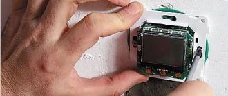
- Equipment for a water-heated floor will require a lot of space. The control of the electrical system is a compact unit, comparable in size to a conventional switch.
The difference is striking - a bulky mixing and manifold cabinet or a compact thermostat installed in a regular socket.
- Water “warm floor” is often impossible in principle in multi-storey buildings. In any case, this will have to be clarified, and if agreed, a project must be drawn up with strictly specified conditions for connecting to the heating network, then approved, agreed upon, etc. For the electrical system, it is only necessary that the total power consumption in the apartment does not go beyond what is permitted. And so - everything is in the hands of the owners, without any approvals or other bureaucratic procedures. From this point of view, electric “warm floors” are completely universal.
Why can’t you install water heated floors in your apartment?
- Whatever one may say, coolant pipes walled up in the floor remain a potential threat of leakage. Albeit with a very low probability, but still...
An accident on a water-heated floor is an infrequent problem, but if it does happen, then eliminating the consequences turns into a very large-scale undertaking.
- Electrical systems are much simpler and more sensitive to control.
- It is easy to start an electric heated floor at any time, for example, when a series of cool days suddenly began in the summer, and the rooms became uncomfortable. Not everyone will decide to run a bulky water heating system with a connected “warm floor” in such circumstances. Yes, and it will not be operational right away.
The only “minus” that immediately comes to mind is the considerable cost of electricity. But this is not a “sentence” at all. With proper installation, reasonable operation, and effective thermal insulation of a house or apartment, nothing frightening awaits the owners. And especially if an electric “warm floor,” as is often practiced, is not created to replace the general heating system, but only to increase the level of comfort in individual areas of the apartment or even in individual areas of the rooms.
Self-regulating system
Self-regulating wire has the best technical parameters. Its composition and mode of operation are completely different from the principle of operation of the cables described above. This wire contains two conductive cores that are in contact with a matrix made of a special polymer material. Due to this semiconductor device, heating is regulated. When the temperature rises, the conductivity of the semiconductor decreases, thereby reducing the heat transfer power. On the outside, the matrix is covered with insulating materials; between them there is a special shielding braid.
A cable like this will last you long enough not to think about repairing it.
For a more accurate understanding, it is worth describing in more detail the principle of operation of such a wire:
- When the room temperature drops, the polymer material in the middle of the cable contracts. This gives a boost to the electricity flowing through the cable, resulting in increased heat transfer.
- When the temperature in the room drops, a reverse reaction occurs, which provokes a decrease in current strength. As a result, the amount of heat generated decreases.
Self-regulating floor heating cable is very popular. This is explained by the many advantages of this type of device over analogues:
- the ability to independently change the heating strength, reacting to the level of room temperature;
- stable multi-layer protection against mechanical impact;
- the unique design of the cable provides protection against overheating, automatically extending the life of the heating element;
- does not require frequent repairs.
The technical parameters of the electric heater make it possible to use this type of cable in different rooms without taking into account the characteristics of the floor covering and areas where furniture is located. Each section of the structure operates independently, independently reacting to external influences and maintaining the temperature specified by the user.
If, under the influence of pressure that may be exerted by household appliances or furniture, the temperature reaches a maximum, the area of the overloaded cable will turn off on its own. At the same time, the remaining sections of the circuit will continue to operate.
When the disabled area cools down, it will again maintain the required temperature. Self-regulating wires are often chosen for living spaces; they are placed under laminate, parquet or tiles.
General structure of a “warm floor” with a heating cable
In order to make a decision on choosing one or another “warm floor”, it is necessary, I think, to understand what the chosen system is and what will be encountered during the installation work.
So, underfloor heating using an electric cable.
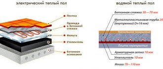
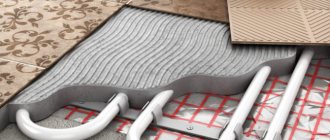
Approximate diagram of a “warm floor with an electric heating cable.”
1 - floor slab.
2 - thermal insulation necessary for the effective operation of the “warm floor” system.
3 - a thin screed covering the thermal insulation and leveling the surface for laying the heating cable.
4 - thin thermal insulating substrate, usually made of foamed polyethylene, with a foil surface. The reflective foil surface should face up.
5 - laid heating cable for “warm floor”.
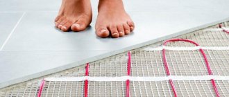
6 — Mounting tapes (tires) to facilitate cable laying. An optional element - the cable is often simply tied to a reinforcing polymer mesh, as shown in the first illustration of this publication.
7 - cement-sand screed, 20 to 50 mm thick, covering the cable, becoming not only the basis for the subsequent laying of the final floor covering (item 8), but also a distributor and accumulator of the heat generated by the cable.
9 - couplings that ensure connection of the heating cable with power wires, or, as they are also called, “cold ends” (item 10).
11 - temperature sensor in a tube embedded in the screed to constantly monitor the heating temperature of the “warm floor”.
12 - Thermostat located in a user-friendly location. Performs the functions of general switching of all suitable wires (“cold ends”, 220 V home power supply cable, temperature sensor signal wire) and control - a well-functioning system will maintain the surface heating temperature specified by the user or according to a programmed algorithm.
The diagram is, of course, only approximate, and in reality there may be both minor and quite serious changes, depending on the design of the floor. But the general principle remains the same: in any case, there must be a layer of thermal insulation under the heating cable.
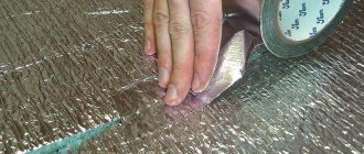
A screed poured over the cable is the optimal solution. But if you look more closely at the projects published on the Internet, you will see that sometimes they even do without it. An example is shown in the illustration below.
One of the options for placing a heating cable in the “bowels” of a wooden floor
In this example, rigid slabs of high-performance insulation with an external foil covering are laid between the joists of a wooden floor. The heating cable was laid along them. The cable is not filled with anything from above - the floorboards are simply installed along the joists.
Yes, such a scheme will also work, but we must correctly understand that high efficiency cannot be expected from it. To create some kind of “comfort zones” is possible, but as an alternative to heating it is out of the question.
Features of application
However, despite the ease of installation of a self-regulating heated floor, some features of its construction should be noted:
- Cutting must be carried out during the installation of the heating floor. In this case, the length of the self-regulating circuit can be either several centimeters or several tens of meters. For different types of cord, the maximum length is different and ranges from 70 to 160 meters.
- When installing heated floors with a self-regulating cable, it should be taken into account that there is a large difference in current between the nominal and starting value, 2 - 4 times. This should be taken into account when choosing ballasts.
By following these expert tips, you will be able to correctly construct a heated floor with your own hands.
Types of heating cables for “warm floors”
For electric floor heating systems, resistive type cables can be used (with traditional heating of the conductor when an electric current is passed through it) or semiconductor cables (the principle is somewhat different there).
Resistive heaters for “warm floors”
They, in turn, are divided into single- and double-wire (or single- and double-wire). And this difference, from the point of view of ease of installation of the system, is very serious.
Single wire heating cable is shown in the illustration below:
Diagram of a single-wire heating cable
1 - a wire (core) with a certain electrical resistance necessary for heating when passing an alternating current of 220 volts.
2 — heat-resistant PVC insulation of the conductor.
3 — shielding copper braiding of the cable.
4 — external general PVC insulation of the heating cable, resistant to the alkaline environment of the concrete screed.
5 - switching couplings in which the electrical connection of the connecting wire and the cold ends is made and insulated (item 6 ). The cable is single-core, so there are two such couplings, but one at each end.
7 — stripped ends of the wires for connection to the thermostat terminals. Two pieces - this is the conductor itself, for connecting to N or L, and the braid - for connecting to the PE grounding, if it is organized in a home network.
Now let’s immediately compare it with a two-wire analogue.
Despite all the similarities, the differences are still very serious
Let's just look at the differences:
1a - instead of one, the cable has two cores (two conductors). They both can be resistive, that is, they participate in heating. But there are cable models in which there is still only one heating core, and the second serves only for switching the circuit.
2a - more serious isolation. That is, first, each core is wrapped in its own heat-resistant PVC insulation, and then, before the copper braid, there is also a common layer.
5a - commutation coupling - there is only one, as well as one “cold end” (pos. 6a ). But at this end there are already three conductors (pos. 7a ) - for connection in the terminals to L, N and PE.
8 — the end sleeve is typical only for two-core cables. It closes an electrical circuit between two conductors, followed by reliable insulation of this node.
It is easy to understand that with equal electrical characteristics and the same required length of the heating cable, a two-wire cable is much more convenient to install. Proof of this is the following diagram:
The difference is in the layout of a single-core (left) and two-core heating cable.
Exactly identical rooms and cable laying pattern. But with a single-core version (on the left, on a greenish background), a prerequisite is that both ends of the cable must converge in one section - to connect to the thermostat. This can significantly complicate installation, also taking into account the fact that cable crossings on the floor are unacceptable. The example, let’s say, is not particularly illustrative, with a very simple circuit, but there are also very complex configurations, and you have to “rack your brain” how to meet all these requirements.
It’s a different matter - a two-wire one, suitable for the thermostat only at one end. The second end with the coupling may be “lost” somewhere in the vastness of the premises - this is completely unimportant, since the electrical circuit is still closed.
heating cable for underfloor heating
Expert opinion
Afanasyev E.V.
Chief editor of the pol-exp.com project Engineer.
There are many ready-made kits on sale, in which the cables (usually two-core) are already laid in a snake pattern on a mesh base. This simplifies the installation of the system, and in addition, it allows you to lay the floor with ceramic tiles directly over the installed heaters, simply making the layer of tile adhesive slightly thicker. Very convenient, especially for “warm floors” in the bathroom, toilet, kitchen, etc.
Mesh mat with laid heating cable
But in essence, these are varieties of a regular resistive cable, just in a slightly “modified frame.”
Self-regulating semiconductor heating cables
But semiconductor cables stand apart, since their ability to generate and dissipate heat is fundamentally different.
Structure of a heating semiconductor self-regulating cable
Such a cable also has two wires (item 1), but neither of them becomes a source of heating. These are just conductors, one of which is connected to the phase, the second to zero.
The wires are enclosed in a semiconductor matrix (item 2). Thus, when the power is turned on, the parallel wires in the matrix set only the potential difference (along their entire length). And conductivity and heating occur precisely due to its unique matrix - we’ll talk about this a little lower.
The rest of the structure is simple - several layers of insulation (item 3), shielding braiding (item 4) and external reliable insulation (item 5), which can easily withstand even immersion of the cable in water (such heating cables are often used for winter heating of water pipes, even with placement inside the pipe).
On one side of such a cable, “cold ends” are connected, on the opposite side it ends with an end sleeve that performs exclusively insulating functions. The wires are not short-circuited anywhere!
How does the matrix work? It is called semiconductor because its conductivity and heat generation directly depend on external conditions, and specifically on temperature.
Change in conductivity of a self-regulating cable matrix depending on temperature
Let's take a look at the diagram. The change in external temperature is shown in shades - from purple to orange. Light dots on the matrix conventionally show open “conductivity paths”, dark dots indicate areas blocked for the passage of current.
Look what happens. The colder the environment around the cable, the more the matrix passes electric current through itself, heating up and giving off heat. But as the temperature rises in a certain area, the conductivity there begins to decrease. And when it reaches a certain level, it generally comes to a minimum, with almost complete blocking of the matrix. It is interesting that all sections (of arbitrary length) are absolutely independent, that is, such self-regulation is differentiated by temperature throughout the entire cable.
Need I say that such a scheme can provide a very significant energy saving effect? And in addition, the likelihood of the cable heating up and the occurrence of any fire hazard for this reason is practically reduced to zero.
SELF-REGULATING HEATING CABLE EASTEC
Thermostats
Thermoregulator (thermostat) is a device designed to control the heating system. Allows each user to control the heating temperature level, reducing or increasing it at will.
In the modern market, accessories of this type are offered in a wide range by various brands. The cost of devices largely depends on the country of origin. The cheapest models are made by China; in the middle price segment, products from Belarusian and Russian enterprises predominate, and the highest prices are asked for products from Danish, Finnish and Swedish brands.
Another cost component is the type of thermoregulatory device. Simple and unpretentious devices with a minimal set of functions will cost the client significantly less than ultra-modern programmable models with an extensive package of capabilities and a memory base that allows you to set the desired heating mode for 3-7 days.
The third pricing factor is the management method. Today, mechanical, wireless, push-button and touch-sensitive thermostats are available for sale. The more complex and sophisticated the design of the device, the more money you will have to pay for it. You can find a mechanic for a fairly budget price, but a modern touch-screen version with the ability to program the system on/off several days in advance will cost a tidy sum.
Before purchasing a thermostat, the user must clearly decide which functions of the device will be used regularly and only then make a choice. There is no point in overpaying for unclaimed features.
Rules for laying cables. Carrying out calculations
In order to correctly plan and calculate your cable “warm floor”, you need to know the basic “postulates” regarding its correct installation.
Thermal insulation
Let's start with the fact that a layer of thermal insulation under the heating system is mandatory. Even if there is a heated room underneath the ceiling. Otherwise, the generated heat will be wasted “in vain” on unnecessary heating of the massive ceiling and the main walls on which it rests. In any case, the ceiling (especially the base on the ground) will be colder than the heating cable, that is, it will “pull” heat onto itself, despite its enormous heat capacity. Heat losses, and therefore electricity costs, will become unacceptably high.
What should the thermal insulation layer be like? Actually, a professional thermal engineering calculation is required. But you can also use their values, derived “in the laboratory” and tested practically.
Below is a diagram showing the dependence of the amount of heat loss (Y-axis) on the thickness of the insulation in millimeters (X-axis). The diagram was compiled based on the results of calculations for a room with an optimal level of thermal insulation of walls, windows, and ceilings (with poor insulation, starting a “warm floor” is a generally pointless task). Extruded polystyrene foam boards (EPS, XPS) with an average thermal conductivity coefficient of approximately 0.033 W/(m×℃) are considered as insulation.
Dependence of the amount of heat loss of a “warm floor” on the thickness of the lower insulating layer
What do we see?
If the insulation is completely neglected, then even in conditions of complete thermal insulation of the room, up to a third of the heat generated by the cable (about 32%) is simply lost.
With increasing thickness, heat loss rapidly decreases. But completely reducing them to zero is unattainable. An interesting feature is that with an EPPS thickness of 30 mm, losses reach 12-13% (almost three times), and then their decline becomes not so “rapid” at all. So, with a thickness of 40 mm, the loss is about 8÷9%. With further increase in thickness, this trend only increases. That is, we can say that a layer of 30÷35, maximum 40 mm will be optimal, and with a further increase in thickness, practically no gain can be expected.
Where is the cable laid? Its length and laying pitch.
Installation of a “warm floor” must be preceded by drawing up an accurate scaled cable layout diagram. What criteria are taken into account?
A similar diagram should be drawn up for each room where the “warm floor” will be installed.
- The installation location of the thermostat (item 1) must be designated so that it is not covered by any pieces of furniture, curtains, etc. Usually it is placed at the level of sockets, one of the devices of the block being created. It is to this point that the power cable corresponding to the power of the “warm floor” should be connected.
- The location of the temperature sensor (item 2) is immediately determined and must be marked on the diagram. The sensor should be placed at a distance of approximately 500÷600 mm from the wall, and always in the middle of the loop of the laid heating cable.
- The diagram should also indicate the location of the couplings - switching and end couplings (positions 3 and 4). Their number and location depend on which cable is used, single- or double-core.
- The drawing indicates the boundaries of the area where the cable will be laid. The fact is that, as already mentioned, it is not placed under stationary pieces of furniture and household appliances (item 5). The distance from the walls (N) is at least 50 mm, and from heating devices or other heat sources - at least 100 mm.
- Using the outlined boundaries, you should then immediately determine the surface area on which the cable will be laid out - we will need this value soon. By the way, it is considered quite normal for the area of the “warm floor” to be about 75% of the total area of the room.
- To apply a “drawing” of the cable layout to the diagram, you need to know the pitch size (in our drawing – D) between adjacent turns, and this cannot be determined in any way without the exact length. And both of these values are “tied” to the required specific heating power.
And this power, in turn, depends on the operating conditions of the heated floor and on the characteristics of the base on which it is mounted (on the ground or, say, above a heated room). You can use the following values:
| Features of the premises and planned operation of the heating system | “Warm floor” is planned to serve as the main source of heat in the room | “Warm floor” will work together with heating, it is created only to increase the level of comfort |
| Floor on the ground or above an unheated room | 180 W/m² | 130 W/m² |
| The floor above the heated room | 150 W/m² | 110 W/m² |
- Further, each manufactured heating cable must have a specific power in the list of characteristics - watts per linear meter of length. For example, 15 W/linear m.
- Having the area and specific power values for the floor and the cable, it is easy to calculate the minimum required length. Well, knowing the length, calculate the laying step.
We will not “torment” the reader with formulas - we will simply offer a calculator that will quickly and accurately calculate both of these quantities.
Let us only add that if, according to calculations, the laying pitch is greater than 300 mm, then it would be better to slightly increase the cable length in order to reduce the pitch. Otherwise, a “zebra effect” may occur, that is, alternating warm and cold stripes on the floor.
Calculator for calculating the length of the heating cable and its laying pitch
Go to calculations
After the calculations, you can finish drawing up the diagram - and you can begin to implement it.
Pros and cons of a self-regulating cable
When planning the installation of a heated floor with self-regulating properties, you should remember that the price of the conductor is high, significantly higher than the price of a conventional wire. However, with a correctly designed project, such a device will cost 40 percent more, no more. Despite this, the system is considered profitable, since it is more economical, and installation costs will quickly pay off.
The main advantages of self-regulating heated floors:
- High reliability, unlike floors with resistive cords. This wire does not overheat, so the likelihood of fire or failure is low.
- The heating circuit is not limited to a certain length, which allows it to be laid on any area, even less than a meter; this is not possible with conventional wire.
- Simple installation, using simple regulators.
- Can be used in areas where the use of explosive devices is prohibited.
- Energy savings, as only cold areas are heated.
- Independence of specific power from length.
- Inaccuracies during installation do not affect the quality of the floor, and even overlaps do not lead to overheating.
It is worth saying that self-regulating floors also have disadvantages:
- high price;
- are not able to warm up the room completely, but only the floor surface;
- the possibility of laying only in a screed of at least 35 mm;
- periodic wear of the fuel matrix;
- service life is only 10 years;
- the starting currents of such a cable are high, especially in the presence of large cold sections, so there is a need for class C circuit breakers.
Important! It is necessary to take into account the readings of the protective blocks from the network; if the temperature around the cable is low, then the current at start will be 1.5 times higher than in operating condition.
Installation of “warm floor” with heating cable
Self-installation - step by step
To install a “warm floor”, you will also have to purchase a thermostat and a temperature sensor (if they are not included in the offered kit). The variety of thermostats is very large; they can be simple, with only a thermostat function, or programmable, capable of working according to a given algorithm. But the diagram of their connection practically does not change.
An example of an electronic thermostat with a temperature sensor included
Most of these devices are designed to be installed in a standard socket. The choice is based on the buyer’s financial capabilities and preferences - from the simplest inexpensive ones to the “sophisticated” ones.
thermostats for heated floors
If everything is purchased, you can start.
| Illustration | Brief description of the operation performed |
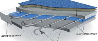
| Some kit manufacturers include a lined “blank” in the box to create a scaled, detailed diagram. For example, like this... | |
| The first step is to use a special drill to select a socket for a standard socket box in the location intended for installing the thermostat. | |
| A vertical groove, approximately 20x20 mm, is cut down from this nest. It should house a corrugated tube with a temperature sensor and the cold end(s) of the heating cable. | |
| Before installing the circuit, all construction debris is immediately and thoroughly removed. | |
| It would be a good idea to prime the floor surface, since the mortar will be laid ahead, and the adhesive qualities of the surface are very important. | |
| The floor has already received the necessary thermal insulation - it is covered with a screed. But the craftsmen decided to enhance the effect and cover the surface with a layer of roll insulation with a reflective surface. The feasibility of such a step, given high-quality insulation, is very controversial, but, of course, it will not make things worse. | |
| After laying the insulation, mounting tapes are attached to the floor surface, which are convenient for fixing the cable. You can fasten, for example, with ordinary dowels. The distance between parallel strips is not regulated, but usually within the range of 500÷1000 mm. | |
| The surface is ready for laying out the cable. | |
| The tapes are often “arranged” with staples and tabs – they are very convenient and easy to secure the cable. | |
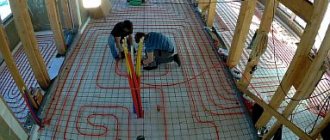
| The cable is laid out and fixed strictly in accordance with the diagram. You can, of course, attach it differently. For example, first a polymer reinforcing mesh is laid out, to which a cable is then tied. The “cold end” of the cable (in this example it is two-core) should approach the groove cut into the wall. | |
| A temperature sensor with a signal cable is inserted into the corrugated tube. It is dragged to the very end of the tube. | |
| This far end of the corrugation is then capped with a plastic cap. | |
| The corrugation with the temperature sensor is placed in its designated place and fixed. Its opposite end fits into the cut out hole. | |
| The cold end of the cable is placed there, in the groove, after which it is sealed with a suitable mortar. | |
| Naturally, by this moment a socket box should already be installed, into which there is a temperature sensor wire and a 220 V power cable. Switching is carried out - to the thermostat terminals. Everything is simple here - the terminals are labeled, and it’s almost impossible to make a mistake. The circuits are tested, the resistance of the laid cable is measured (indicated in the passport), and the system is tested for literally a minute to make sure that heating has started. If everything is normal, the system is de-energized, and the owner will be even calmer if the thermostat is removed before the end of the work, so that no one accidentally turns it on. Putting this device back in place is a five-minute task. | |
| Next, the cable must be closed with a tie. Since in our example it was decided to lay additional insulation, we will have to cut out windows in it for contact of the screed with the base. The windows are cut about 200 mm long, 50 mm wide, in a checkerboard pattern, with a spacing of about a meter in one row. | |
| If necessary, a beacon system is installed. Well, what takes longer is laying out the mortar and leveling it. The laying (pouring) technology may be different, depending on the chosen composition for the screed. | |
| The poured screed is left until completely dry. In the first week, it is recommended to moisten it daily and then cover it with plastic wrap. It is strictly forbidden to “speed up” the readiness of the screed by turning on the heating system - all the work will go down the drain. The screed must gain strength exclusively under natural conditions. |
After this, if other repair tasks in the room are completed, you can install a thermostat and start the system. But even here some caution is required. It is not recommended to turn on the “warm floor” immediately at full power. They usually start at 15 degrees, and then add five degrees every day until they reach the planned regime. This way the floor structure will gradually fully adapt to the heating system.
Additionally, we recommend that you familiarize yourself with information about which manufacturer of heated floors is best to choose based on the 2019 rating