Home / Boiler rooms
Back
Published: 02/28/2020
Reading time: 6 min
0
7171
Thermal diagram of a boiler room is intended for a graphical representation of the main and auxiliary equipment, and interconnection using utility networks. Such schemes are mandatory when developing project documentation; they are carried out using elements approved by SNIP.
The diagram shows the flow of coolant through the pipes to the heating devices, boiler, tank and pump. The lines indicate the location of control valves and safety devices.
- 1 What is the difference between basic and detailed thermal circuits?
- 2 What is the difference between closed and open system schemes
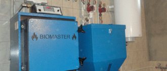
- 3 Boiler room diagram when using solid fuel
- 4 Plan with electric boiler
- 5 Scheme with a gas boiler
- 6 Boiler in the boiler room diagram
- 7 Harness with hydraulic arrow
- 8 Diagram of a boiler room with 2 boilers
What is the difference between basic and detailed thermal circuits?
Thermal heat supply schemes can be basic, detailed and installation. The schematic diagram of the boiler room shows only the main thermal power equipment: boilers, heat exchangers, deaeration units, chemical water purification filters, feed, make-up and drainage centrifugal pumps, as well as utility networks that connect all this equipment without specifying the number and location. This graphic document indicates the costs and characteristics of coolants.
The expanded thermal diagram reflects the installed equipment, as well as the pipes with which they are connected, specifying the location of shut-off and control valves and safety devices. In the case when it is impossible to plot all the nodes on a detailed thermal circuit, then it is separated into its component parts according to the technological principle. The boiler room flow diagram provides detailed information on the installed equipment.
Advantages of a liquid fuel boiler
Installing an oil-fuel boiler is much easier than a gas or solid-fuel counterpart. You can place it in the house and in the yard.
The main advantage is the absence of the need for approval and obtaining permits. All that is required from the owner of the house is to provide free access for a car with fuel and regularly refuel the boiler.
If there is no gas main near the country house, you can install a unit that runs on diesel fuel in the boiler room. A double-circuit boiler will heat the house and provide residents with warm water
To obtain 10 kW of power, about 1 liter of diesel fuel is consumed, but the exact consumption depends on the quality of the fuel. In the middle zone, with a house area of 200 m², about 5 thousand liters of fuel will be required for the heating season. The chimney must be cleaned periodically.
To install a diesel boiler, an average of 4 m² is required. If supply ventilation is provided by air flow from other rooms of the house, then per 1 kW of boiler power there should be at least 30 cmᶾ of air. With external ventilation this figure decreases to 8 cmᶾ.
What is the difference between closed and open system schemes?
The main difference between an open or gravity heating system and a closed one is the complete absence of devices for forced movement of the coolant through the pipes. This process occurs only due to the thermal expansion of the heated liquid.
Composition of elements in the thermal circuit of a boiler house with an open heat supply circuit:
- The heating source is a hot water boiler operating on solid, liquid and gaseous fuel.
- Expansion tank for thermal compensation of the coolant.
- Temperature compensator overflow pipe.
- Supply (hot) line with heating risers.
- Heating appliances.
- Return line with heating risers.
- Coolant drain valve.
- Heating network feed valve.
The circulation of the heating fluid in a closed boiler installation is carried out thanks to a circulation pump (3), which is installed on the water outlet line from the boiler (1), usually in its upper part, and an air vent (4) is also located here. Water, heating up in the boiler, enters the heating supply pipeline and is directed to the batteries (9) through a thermostatic valve (8).
An expansion tank (7) is installed on the supply line for temperature compensation of water during heating, a safety valve (6) for relieving emergency pressure in the network and a pressure gauge (5) for monitoring the working pressure of the medium.
A Mayevsky valve is installed on the heating device to release the air lock (10). Along the return flow of the coolant, a three-way valve (17), a water purification filter (13), a shut-off valve (15) and a drain valve (14) are installed.
Gas is supplied to the boiler through a gas valve (18) and a filter (19) to purify the energy carrier before the nozzle of the burner device. Make-up water in the water-heating boiler house circuit comes from the water supply system (11) through the valve (16) to the filter to remove suspended solids and hardness salts. The boiler is equipped with a hot water supply line for its own needs (2).
Boiler room ventilation and combustion air heating circuit
This circuit is the internal circuit of the boiler room, the heat from which is used for its own needs. It is an independent circuit separated by a heat exchanger.
A three-way mixing valve is installed on the heating side of the supply pipeline, which maintains the set temperature on the heated circuit of the heat exchanger according to the temperature sensor. The temperature is maintained by mixing coolant from the return pipe from the heat exchanger.
On the heating side, a circulation pump is installed on the return pipeline, which circulates the coolant through the heat exchanger. The pump runs all the time while the circuit is on, with a constant flow rate.
On the heated side of the heat exchanger, ventilation equipment (ventilation unit, air heaters) is connected, providing standardized ventilation in the boiler room and/or heating of combustion air.
Anti-freezing liquids based on glycol are used as a coolant. This necessitates the need to separate the ventilation circuit with a heat exchanger. On the glycol side, a circulation pump is installed on the return line, which circulates the coolant through the ventilation equipment. The pump runs all the time while the circuit is on, with a constant flow rate.
To compensate for temperature expansions, an expansion tank is provided in the radiator heating circuit, equipped with a safety valve that protects the tank from excess pressure by releasing the coolant. The coolant is discharged into a specially installed glycol solution storage tank. The glycol circuit is also fed from it using a special make-up pump.
Boiler room diagram when using solid fuel
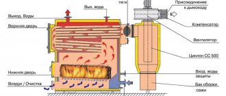
Solid fuel boilers have a certain disadvantage, which is caused by high inertia of operation, due to the impossibility of fine adjustment of the combustion process of solid fuel.
In order to smooth out the disadvantage, a buffer tank is installed in the circuit, which gains temperature to heat the heating circuit and consumes heat over a long period of time.
This thermal diagram of a solid fuel boiler house consists of:
- Heat supply source with a primary heating circuit: solid fuel boiler;
- safety group with safety valve;
- buffer capacity;
- heating circuit circulation pump;
- boiler circuit circulation pump;
- expansion tank;
- shut-off valves, drains, air vents;
- balancing valve;
- heating circuit mixing unit for automatically maintaining the temperature in the radiators;
- mixing unit of the boiler circuit, for optimal boiler operation;
- weather-compensated or customizable automation with emergency alarm.
The value of a heat accumulator in a boiler room
Thermal accumulators, otherwise called buffer tanks, are most effective in boiler rooms of private houses with solid fuel boilers. Their use allows you to create contours with natural circulation. These are the paths along which the coolant moves during a power outage, and, as a result, the pump stops working.
The operating principle of a heat generator with a heat accumulator is as follows:
- simultaneously with the supply of heat to the heating system, the heat supply heats the medium in the buffer tank;
- after turning off the TT boiler, the temperature sensor signals the pump, which initiates the supply of the media accumulated in the heat accumulator tank to the network;
- When the required temperature is reached, the sensor sends a signal to turn off and the heat supply stops.
Cooling of the coolant occurs slowly, thanks to good thermal insulation. Cycles of starting and stopping the pump occur many times until the water in the heat accumulator cools down.
When tying with heating equipment, a large number of turns and bends should be avoided. The diameter of the pipes must correspond to the boiler pipes.
Buffer capacity value:
- improved safety;
- economic benefit;
- creating more comfortable conditions.
Plan with electric boiler
An electric boiler is a unit that heats a coolant by converting electricity into thermal energy. It is used as a heat supply source for small suburban houses or as an emergency source with a gas or solid fuel boiler.
Based on the modification of such devices, various schemes for connecting electric boilers to heating are used. The most popular is a multi-level heating system with a combination of heating devices in the form of radiators and a “warm floor” system.
Basic elements of electric heating for a private house:
- Heating source, electric boiler.
- Safety group, with air vent, safety valve and pressure gauge, to relieve excess pressure in the network.
- Collector for directing water along contours.
- Radiators.
- Heat exchanger for hot water supply.
- Expansion tank for hydraulic compensation of the system.
- Manifold for the "warm floor" system.
- Warm floor system.
- Filter for cleaning coolant from suspended substances.
- Check valve.
- Electric circulation pump.
- Power supply networks.
- Automatic security with alarm.
Types of boiler houses for the private sector
The requirements for boiler houses are set out in SNiP with the nomenclature designation II-35-76.
Depending on the location of the room with heating equipment installed in it, boiler rooms can be classified into one of the following types:
- built-in;
- free-standing;
- attached.
The dimensions of the room allocated for the boiler room are selected based on the type of fuel and the type of boiler design.
When it is difficult to arrange a special room for a boiler room, there is another option - a mini-boiler room.
It is placed in a container assembled according to the principle of metal structures, which can be placed in the courtyard of the house. All that remains is to connect the mini-boiler room to the communications.
Image gallery
Photo from
Selecting a boiler room by type of placement
Freestanding boiler room
Location of private boiler room
Combustion product removal system
The not very popular popularity of such modules is explained by their rather high cost. If there is a prospect of allocating space for a boiler room in the basement, you can buy the equipment separately. Then the heating system will cost much less.
A mini-boiler room in the courtyard next to the mansion eliminates the need for design work, construction and arrangement of a separate room, and ventilation equipment. The container already contains everything you need for the efficient functioning of the heating system
Scheme with a gas boiler
Gas boilers are the most economical and functional heating sources. The small building essentially houses a mini-boiler room in a private house.
Manufacturers of modern boilers equip the casing with all the necessary equipment in the form of pumps, an expansion tank, a safety relief valve and an air vent. The owner of such equipment only needs to connect the unit to the heating and hot water circuit, which significantly reduces installation costs.
But the main advantage of a comprehensive boiler assembly is the consistency of the operation of all auxiliary components that have been tested and adjusted in the factory.
The simplest thermal diagram of a gas boiler room:
- The source of heat supply is a gas boiler.
- Safety group, with air vent, safety valve, pressure gauge and expansion tank.
- Supply of coolant to heating devices.
- Coolant return from heating devices
- Heating radiators
- Supply of tap water to recharge the heating network with a filter and shut-off safety valves.
- Supply of tap water to the DHW circuit of the boiler.
- Filter for coarse cleaning of coolant from suspended solids on the return line.
- Check valve on the return line.
- Circulation pump on the return line.
Operation of two boilers in a boiler room
Today, a scheme with two boilers is in great demand in boiler rooms of private houses. The key importance lies in the issue of their consolidation. The solution to the problem is automation of equipment operation.
Manual switching between boilers is carried out by independently closing two taps. The remaining two remain open. In automatic mode, the functions of the regulators are taken over by 2 check valves to prevent unnecessary movements through the switched-off equipment.
The paths for moving the coolant in an automated process are always free. In any case, the pump of a functioning boiler drives it through an inactive unit in a small circle. The problem of idling is designed to eliminate return devices located, for example, on the return branch.
Another element of automation is a thermostat, which signals the equipment to stop working. Until this happens, the coolant will uselessly circle in the circuit through the stopped device, creating interference with the operation of the switched on device.
Boiler in the boiler room diagram
There are various options for connecting an indirect heating boiler to boiler units that can operate on any type of fuel: gas, solid and liquid fuel.
In this scheme with an indirect heating boiler, a water gun or distribution manifold is not installed. The installation of these elements is associated with certain difficulties, as it creates a very complex hydraulic system.
This scheme uses 2 circulation pumps - for heating and domestic hot water. The heating pump runs continuously when the boiler room is running. The DHW circulation pump is started by an electrical signal from the thermostat installed in the tank.
The thermostat detects a drop in the temperature of the liquid in the tank and transmits a signal to turn on the pump, which begins to circulate the coolant along the heating circuit between the unit and the boiler, heating the water to the set temperature.
This scheme is used for all modifications of heating sources installed in both hot water and steam boiler rooms.
A certain modification of the circuit is allowed when a low-power boiler is installed in it. The electric heating pump can be turned off by the same thermostat that turns on the pump to the boiler.
In this option, the heat exchanger heats up faster and the heating is stopped. With prolonged inactivity, the temperature in the room will drop.
In addition, after warming up in the boiler is completed, the pump in the heating circuit comes into operation and begins to pump cold coolant into the boiler, which causes the formation of condensation on the heating surfaces of the boiler and leads to its premature failure.
The process of condensation can also occur in the case of long pipelines laid to the batteries. With a large heat removal from heating devices, the coolant can similarly cool down greatly, and the low return temperature will harm the operation of the boiler.
To protect it from condensation and water hammer that occurs when cold water comes into contact with hot heating surfaces, the system is equipped with a protective circuit equipped with a three-way valve.
The diagram shows a temperature of 55C. The thermostat integrated into the circuit automatically selects the required flow rate to maintain the return coolant temperature.
Unregulated heating (ventilation) circuit
There are no control valves on this circuit. This means that the temperature in the circuit will be equal to the temperature at the outlet of the hydraulic needle.
A circulation pump is installed on the return pipeline, which ensures the circulation of coolant among consumers. The pump runs all the time while the circuit is on, with a constant flow rate.
To compensate for temperature expansions in the heating (ventilation) circuit, an expansion tank is provided, equipped with a safety valve that protects the tank from excess pressure.
At the outlet from the boiler room on the heating (ventilation) circuit, a heat metering unit is installed, which keeps track of the thermal energy supplied to consumers.
Harness with hydraulic arrow
In complex multi-level heat supply systems, a hydromechanical distributor - a hydraulic switch or a manifold - is often used to balance fluid flows in various sections of the circuit with individual circulation pumps.
A similar scheme of a boiler unit involves turning on an indirect heating boiler through a pump NB and NR, radiator heating through a pump NK1 and NK2, and a warm floor through H1.
It can operate without a hydraulic module; in this case, balancing valves are installed to compensate for pressure drops in various “branches” of the system.
Complete set of thermomechanical equipment:
- Heat supply source – 2.
- Safety group, with air vent, safety valve, pressure gauge and expansion tank.
- Supply of coolant to heating devices.
- Coolant return from heating devices
- Heating radiators.
- Warm floor system.
- Indirect heating boiler
- Filter for coarse cleaning of boiler water from suspended solids on the return line.
- Check valve on the return line.
- Circulation pumps: through the main pipeline, in the underfloor heating circuit and indirect heating boiler.
Adjustable radiator heating circuit for boiler room
This circuit is the internal circuit of the boiler room, the heat from which is used for its own needs.
A three-way mixing valve is installed on the supply pipeline, maintaining the set temperature on the radiators with adjustment to the temperature inside the boiler room. The temperature is maintained by mixing coolant from the return pipeline. This means that the temperature at the outlet of the hydraulic needle must always be higher than or equal to the temperature at the radiators.
A circulation pump is installed on the return pipeline, which circulates coolant through the radiators. The pump runs all the time while the circuit is on, with a constant flow rate.
To compensate for temperature expansions, an expansion tank is provided in the radiator heating circuit, equipped with a safety valve that protects the tank from excess pressure.
Boiler room diagram with 2 boilers
The use of two gas units for one heating system is a fairly popular solution among owners of autonomous heating systems with a system thermal power above 50 kW.
This may be a large heated area of the facility, or the presence of additional heat loads in the form of hot water or air-heated heating units.
The use of two units per thermal circuit has a number of advantages compared to one source of equivalent power. First of all, because several small-sized units of less weight are much easier and more economical to place in a boiler room, which is especially important when constructing roof-mounted or semi-basement furnaces.
In addition, the installation of 2 units significantly increases the operational reliability of the heat supply system. In the event of an emergency stop of one of the units, it will continue to function with 50% thermal load.
This piping scheme significantly increases the working life of boilers, due to the fact that they are less loaded during the heating period of the year.
Gas boiler room for your home
Gas is an explosive substance, so the requirements for gas boiler houses are very strict. If a boiler with a power of up to 30 kW is sufficient to heat the house, then there is no need for a separate room for the boiler room.
The boiler can be placed in a well-ventilated kitchen on a wall made of non-combustible materials, provided that the volume of the room is at least 15 m ᶾ, the height from floor to ceiling is from 2.5 m, and the floor area is from 6 m².
If there are no walls made of non-combustible materials in the kitchen, then the boiler is installed on a surface plastered and insulated with a special screen
All requirements for gas boiler houses are related to preventing the consequences of possible gas leaks. For this purpose, the window area in the room where gas equipment is installed starts from 0.5 m², and the door width from 0.8 m.
The chimney of such a boiler room must rise above the roof ridge by at least 500 cm and have an additional channel for cleaning. Condensate collectors must be installed on the chimney and ventilation.
When gas enters the boiler, electronic or piezo ignition is turned on. A spark occurs and it ignites the igniter, and from it the main burner, heating the coolant to the set temperature. Next, the automation turns off the burner
If the power of a gas boiler exceeds 30 kW, then a separate building is required for it.
The requirements for a separate boiler room are set out in the building codes:
- the foundation of the boiler room building must be separate from the foundation of the house;
- a certain percentage of sand must be present in the concrete solution used in the construction of the building;
- a separate foundation is placed under the boiler, raising it above the finished floor by 0.2 m;
- under the boiler you need a backing made of flat slate or tiles protruding beyond its limits by 0.1 m along the entire perimeter;
- to drain the coolant in case of an emergency, the boiler room must be equipped with a sewerage system;
- within a radius of 0.7 m around the boiler, the space must be free;
- interior decoration must have a fire resistance rating of 0.75 hours.
There are special regulatory requirements for the boiler itself, since it does not belong to the category of household appliances, but to the category of complex engineering equipment. Gas boilers, like all others used in the domestic sector, must have a certificate certifying that they have passed a safety examination.
Control services will never give permission to put into operation a boiler room with a gas boiler if there is no gas detector in the room.
Questions and answers about the boiler room and boiler room equipment
What does the boiler room equipment consist of? In this article you will find all the answers to your questions.
What is a boiler room distribution manifold and why is it needed?
The boiler room distribution manifold is the main device for distributing coolant from the boiler to consumers - radiators, hot water boiler, heated floor, etc. The distribution manifold combines a comb, pumping and mixing groups and a hydraulic separator (hydraulic arrow). The purpose of the listed elements of the distribution manifold is described in the answers to the following questions.
What is a “pump group”?
A pumping (more precisely, pumping and mixing) group is a device for regulating the temperature and ensuring the circulation of coolant in a separate heat supply circuit (heating, hot water boiler, heated floor, pool heating, etc.). In general, it consists of a mixing valve, a circulation pump, shut-off valves and instrumentation. For some circuits (DHW boiler circuit, swimming pool heat exchanger circuit) there is no mixing valve. As a rule, the mixing valve is part of the distribution manifold of the boiler room and is mounted directly on the comb.
What is a “hydraulic separator”?
A hydraulic separator or hydraulic arrow is a device in the distribution manifold that performs several functions:
— hydraulic separation of the coolant circulating through the boiler and through the distribution manifold. At the same time, when the coolant flow through the heat supply circuits (heating, hot water boiler, etc.) changes, the coolant flow through the boiler remains constant, which optimizes the operation of the boiler and extends its service life;
— removal of air dissolved in the coolant. Due to the design features of the separator, this happens much more efficiently than simply using automatic (and even more so manual) air removal valves;
- captures the smallest contaminants that are not retained by mesh filters. These contaminants are deposited at the bottom of the separator, from where they are removed through a special tap. The use of a hydraulic separator improves the quality of operation of the boiler room and heating system of a private house, increases the service life of the boiler and is recommended for use in all individual boiler rooms. And for boiler houses with boilers with a power of more than 50 kW, its use is mandatory.
What are “circuits” in a boiler room?
A boiler room circuit is a part of a heat supply system whose coolant parameters differ significantly from the parameters of the coolant supplied by the heating boiler.
- 1. Radiator heating circuit
- 2.Water heated floor circuit
- 3. Hot water boiler circuit.
The heating boiler prepares coolant with a temperature of 80 degrees Celsius, and for individual heating circuits it is necessary:
— for the heating circuit, the coolant temperature should be 80/60 degrees (forward and return lines), with an almost constant coolant flow;
— for a heated floor circuit, the coolant temperature should be 45/40 degrees, also at a constant flow rate;
— for the DHW boiler circuit, the coolant temperature should be 80/60 degrees, while this circuit has a sharply variable coolant flow rate: from zero in standby mode, jumping to 100% in the mode of heating domestic water in the DHW boiler.
The required temperature for each heating circuit is prepared and maintained by the corresponding pumping and mixing group (description of the pumping group is in the answers to the questions).
Sometimes, when building a heating system in the “Comfort+” option, the division into separate circuits is carried out based on maximum comfort when using the system. At the same time, heating systems (and/or heated floors) of different floors can be separated into separate circuits, which makes it possible to organize the most rational and convenient for the consumer maintenance of the required temperature in the premises of the house (floor-by-floor regulation).
Why do you need a heating expansion tank?
A heating expansion tank is needed to compensate for the increase in coolant volume when it is heated. With a serviceable and correctly selected expansion tank, the pressure in a closed heating system remains constant when the temperature of the coolant changes. The volume of the expansion tank is calculated in a heating project for a private house and depends on the volume of coolant in the heating system.
What is an over-the-wall chimney and when can it be used?
Such a chimney (“through the wall”) is used when installing a wall-mounted boiler with forced removal of flue gases using a special fan.
In this case, the chimney is a “pipe in a pipe” (coaxial chimney), with the internal pipe discharging flue gases behind the wall, and through the external pipe the same fan takes in the air needed for combustion from outside.
A chimney “through the wall” is 2-3 times cheaper than a conventional one, it facilitates the installation of wall-mounted boiler equipment, since it is not necessary to organize a flow of combustion air into the room with the boiler, but it has a number of restrictions on the location of the outlet on the wall (distance from windows and doors) and for stable operation in severe frosts.
What is an “open” and “closed” combustion chamber of a boiler?
The combustion chamber of a boiler is called open, in which air for the combustion process is supplied naturally, usually from the room in which the boiler is installed. That is, the burner is “open” for air flow. Boilers with open combustion chambers operate with an atmospheric smoke removal system (natural draft).
The closed combustion chamber is insulated, and combustion air is supplied into it by a fan (usually from outside the room). Wall-mounted boilers are usually equipped with closed combustion chambers, and the removal of combustion products is forced using a special fan (see “chimney through the wall”).
What is a “double-circuit” boiler and when is it best to use it?
Double-circuit boilers are those that, without additional devices, can not only heat a house, but also produce hot water for domestic needs. Such boilers usually have two heat exchangers. In one, which is called primary, the coolant is heated using a burner. In the second, household water is heated with the help of a coolant, which then flows to the hot water tap. Since household water is heated with the help of a coolant inside the boiler itself, during the time the water is drawn from the hot tap, the coolant does not flow into the heating system of the house (the so-called “DHW priority”). For this reason, when using double-circuit boilers, it is impossible to recirculate hot water (with a constant flow of water in the case of recirculation, the boiler will always work only to heat hot water).
It is advisable to use such boilers when the number of hot water supply points is small (for example, a kitchen sink, sink and shower in the bathroom) and the distance from the boiler to the most distant point of hot water collection is insignificant (for example, a bathroom and kitchen through the wall), and therefore no the need for a hot water recirculation system.
In cases where hot water consumers are located at a greater distance than “through the wall” or on another floor, the use of a double-circuit boiler is not recommended, due to the reduced comfort of using hot water.
What is a boiler “safety group”?
A boiler safety group is a device that protects the boiler and the entire heating system from unacceptable excess pressure in emergency situations.
As a rule, the safety group for domestic heating boilers consists of a pressure gauge, an automatic air vent and a safety valve.
The pressure gauge displays the pressure parameters in the heating system and has indicators of the minimum and maximum permissible pressure.
An automatic air vent removes air from the heating system, preventing “airing” of the system and the resulting cessation of coolant circulation in it.
The spring safety valve is set to the maximum operating pressure in the heating system (usually 2.5 or 3 bar), and when this pressure value is exceeded, it opens, releasing excess coolant from the system. Each valve has a plate indicating its response pressure and a device for checking its operation. A boiler safety group must be installed in an individual boiler room; the selection of its model depends on the power of the boiler and is carried out in a heating project for a private house.
