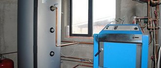
As the diagram shows, to raise the temperature in the container in order to prevent corrosion, the required amount of heated liquid enters the pipes. It runs from the boiler along a line called recirculation. The pumping equipment of the same name pumps hot coolant, sending it to the batteries.
If the temperature outside is not below 0 °C, there is no need to heat the room too much. Therefore, the principle operates in which the high-temperature coolant from the network pump moves to the bypass line without entering the heating element. Here it is mixed with the hot water supply.
The temperature of the coolant supplied to the liquid supply network, specified by engineering calculations, is formed. Chemically purified water is heated and deaerated in the appropriate equipment. The liquid is then sent from the container where it is stored using a make-up pump element into a line of pipes leading to the batteries.
The working water tank holds it in place until the room needs to be reheated.
Water heating boiler design
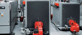
Types of water heating boilers for home and industrial use
The fundamental design of heating devices is approximately the same and may differ in such indicators as fuel consumption, power, size and country of origin.
A standard water heating boiler consists of the following parts:
- steel body;
- burner;
- wick;
- inlet pipes (located at the bottom);
- outlet pipes (located on top of the body);
- steam valve;
- the combustion chamber;
- water heat exchangers;
- firebox with door;
- blower with handle;
- chimney with valve and protective cap.
The firebox of solid fuel boilers is equipped with grates designed to accommodate fuel and drain waste products (slag, ash, ash) into the ash pan.
The operating principle of water heating boilers is as follows:
- loading fuel into the firebox and setting it on fire (connecting an electric heating element);
- filling the circuit and heat exchanger with water;
- the liquid heats up and, under the influence of a pump or due to a pressure difference, moves by gravity through the pipes;
- combustion products are discharged through a conventional or coaxial chimney;
- the valve regulates the supply of air necessary for combustion of the fuel.
The boilers are made of durable heat-resistant steel that can withstand high temperatures.
Adding hot water and adding valves
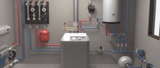
In order for the system to work, it is necessary to ensure automatic addition of hot water to the return line. This way we increase the temperature of the water entering the boiler. If too cold coolant gets into it, the boiler can quickly fail. There are several common piping schemes with the addition of a return line. We use a three-way thermostatic mixing valve. Installing this valve allows you to create a small circle of circulation of the coolant, as a result of which the heating of the boiler will accelerate. This approach prevents the formation of condensation, thereby protecting the heat exchanger from breakdowns due to significant temperature differences.
Let's imagine a simulated situation. We will set the built-in petal valve to activate when the temperature reaches 55 degrees. When the boiler starts, the water in the system is not heated and while it is cold, the valve closes and lets the medium flow in a small circle. After the supply water warmed up to a threshold value of 55 degrees, the valve opened slightly and began to mix in cooled water from the return. At the next stage, the entire barrel is heated, and the return temperature will also rise above 55 degrees. At this point, the valve will switch completely and release water through the large ring.
After connecting the return line to the solid fuel boiler, we add a pressure relief valve. It is necessary in case of exceeding performance indicators. The solid fuel boiler has a special hole for mounting the valve. In other models, the valve can be installed through a tee. We include an expansion tank in the system. After this, to complete the piping on the heat generator side, it is necessary to connect the electric boiler. It is included in the circuit in parallel with an already installed solid fuel boiler.
We have two feeds, and check valves need to be installed on each of them. This is done so that the pump of one of the boilers does not pump water along the working circuit in the opposite direction to the other. Let us remind you that on a solid fuel boiler we use not a regular valve, but a reed valve.
Modifications by fuel type
A solid fuel hot water boiler operates on wood, coal, pellets, wood chips.
Based on the method of heating the coolant, two types of boilers are distinguished:
- Water tube. In them, the liquid is heated in a heat exchanger under the influence of the heat of burning fuel. The smoke is discharged outside through an insulated chimney.
- Gas pipes. It uses the energy of gases produced during combustion. They pass through a pipe, on top of which another external pipe containing liquid is installed.
Devices can be universal or run on only one fuel. Classification of hot water boilers:
- Solid fuel. The units can be fueled with coal, firewood, briquettes, plastic and rubber. They have a simple and reliable device, but they heavily pollute the environment.
- Gas fuel. They are the best option in terms of environmental friendliness and efficiency. They are distinguished by high reliability and safety. A gas hot water boiler is an excellent choice if it is possible to connect to an industrial main.
- Liquid fuel. They run on diesel fuel, but can also burn other liquid hydrocarbons. The principle of operation is similar to gas analogues, but they emit toxic smoke.
- Electrical. They are the cleanest in terms of ecology, since there are completely no by-products. The downside is that energy is expensive and heating costs can be prohibitive.
The choice of boiler is based on market analysis and fuel costs. Priority should be given to economical options and universal designs.
Boiler room auxiliary equipment
In order for heat transfer processes to occur effectively in the boiler, all flows of water, fuel and air must undergo a preparation process before being supplied to the unit. These tasks are performed by auxiliary boiler installations.
Group of pumps in a boiler roomThe auxiliary elements of the boiler unit include the following devices:
- fuel supply systems;
- smoke purification systems;
- draft devices;
- feed and circulation pumps responsible for the movement of water along the circuit;
- boiler separation devices;
- water treatment plant.
Draft devices include smoke exhausters and fans operating in the gas-air duct system of the boiler. The former serve to create a vacuum in the combustion chamber and remove flue gases through the chimney into the atmosphere.
They are installed between the flue and the chimney, usually outside the boiler room, at the back of the boiler, due to the high noise level generated during operation.
Fans are designed to force air into the combustion chamber, to create a gas-air mixture at the outlet of the gas burner, to ensure complete combustion of the fuel. The device is also installed outside the boiler house building, but in front of the boiler front.
Separation devices are used to separate steam from boiler water; they are installed in the upper drum of the boiler. The water treatment system purifies feed water from hardness salts in sodium cation exchanger filters to reduce scale formation processes on the boiler heating surfaces of the boiler and removes active oxygen in the deaeration-feeding unit to reduce corrosion processes in the internal heating surfaces of the heat generator.
To power steam boilers, at least two electric pumps are installed, with an operating pressure of at least 1.25 pressure of the boiler water path, and a productivity of 110% of the rated steam output of all operating boilers.
In addition, two steam pumps are installed with at least 50% of the boiler room’s rated output.
Boiler room pumps are divided into:
- Feeding - designed to supply feed water to the boiler.
- Make-up tanks - for recharging the heating circuit in case of coolant leaks in the main networks.
- Network for coolant circulation in the supply and return pipelines. They are also used for hot water boiler houses.
- HVO pumps - in the chemical water treatment system.
- Gas equipment.
Classification by type of accommodation
Wall-mounted water heating boilers have a relatively small weight, in contrast to floor-standing models.
Water heating devices, depending on the power and design, have different weights and sizes. This largely determines the place where they can be installed.
Floor products are characterized by significant weight and dimensions. It is impossible to hang them precisely because of these factors, since not every load-bearing surface can withstand such a load. The advantage is that such devices are more reliable and functional.
Wall-mounted boilers are compact and light in weight. Their development was initially aimed at ensuring that the products could be installed in tight spaces - kitchen, bathroom, basement. Due to size restrictions, such boilers are not designed for high power; the close arrangement of parts makes them difficult to service and reduces the level of reliability.
Boiler room auxiliary equipment
In order for heat transfer processes to occur effectively in the boiler, all flows of water, fuel and air must undergo a preparation process before being supplied to the unit. These tasks are performed by auxiliary boiler installations.
Group of pumps in a boiler room
The auxiliary elements of the boiler unit include the following devices:
- fuel supply systems;
- smoke purification systems;
- draft devices;
- and pumps responsible for the movement of water along the circuit;
- boiler separation devices;
- water treatment plant.
Draft devices include smoke exhausters and fans operating in the gas-air duct system of the boiler. The former serve to create a vacuum in the combustion chamber and remove flue gases through the chimney into the atmosphere.
They are installed between the flue and the chimney, usually outside the boiler room, at the back of the boiler, due to the high noise level generated during operation.
Fans are designed to force air into the combustion chamber, to create a gas-air mixture at the outlet of the gas burner, to ensure complete combustion of the fuel. The device is also installed outside the boiler house building, but in front of the boiler front.
Separation devices are used to separate steam from boiler water; they are installed in the upper drum of the boiler. The water treatment system purifies feed water from hardness salts in sodium cation exchanger filters to reduce scale formation processes on the boiler heating surfaces of the boiler and removes active oxygen in the deaeration-feeding unit to reduce corrosion processes in the internal heating surfaces of the heat generator.
To power steam boilers, at least two electric pumps are installed, with an operating pressure of at least 1.25 pressure of the boiler water path, and a productivity of 110% of the rated steam output of all operating boilers.
In addition, two steam pumps are installed with at least 50% of the boiler room’s rated output.
Boiler room pumps are divided into:
- Feeding - designed to supply feed water to the boiler.
- Make-up tanks - for recharging the heating circuit in case of coolant leaks in the main networks.
- Network for coolant circulation in the supply and return pipelines. They are also used for hot water boiler houses.
- HVO pumps - in the chemical water treatment system.
- Gas equipment.
Specifications
Heat exchanger of an industrial water heating boiler
The main technical characteristics of water heating equipment are as follows:
- device - fire tube, water tube;
- operating temperature - low temperature (up to + 115 ºС), high temperature (+ 115-200 ºС);
- coolant - water;
- functionality - single-circuit (heating only), double-circuit (heating, hot water supply);
- nominal pressure in the system - 0.6-0.8 MPa;
- produced power - 3-28 kW;
- types of fuel - firewood, briquettes, gas, diesel, mining, fuel oil, electricity;
- control - manual, automatic.
The choice of product is made based on its purpose, size and configuration of the facility in which it will be installed.
Steam boiler diagram
Coolant flow diagram
PCs are installed in the boiler room, which can be located in separate, adjacent and built-in non-residential buildings.
Designations according to the diagram:
- Gas steam boiler fuel supply system, No.1.
- Combustion device - firebox, No2.
- Circulation pipes, No.3.
- Zone of steam-water mixture, evaporation mirror, No.4.
- Direction of feed water movement, NoNo5,6 and 7.
- Partitions, No8.
- Gas flue, No.9.
- Chimney, No.10.
- Output of circulating water from the steam boiler tank, No.11.
- Purge water drain, No.12.
- Boiler top-up with water, No.13.
- Steam manifold, No14.
- Steam separation in the drum, NoNo15,16.
- Water indicator glasses, No17.
- Saturated steam zone, No.18.
- Steam-water mixture zone, No.19.
Operating rules
You can avoid an accident with a hot water boiler by observing safety precautions during operation.
The service life of the boiler depends on the quality of its manufacture, the solutions used in the assembly and compliance with operating standards. Installation of the device must be carried out in strict accordance with the technical description of the product and the drawing.
Using the device requires compliance with the following rules:
- use only those types of fuel that are listed in the instructions for the device;
- when using solid fuel devices, have containers for filling extracted ash;
- the firebox door must be kept closed at all times;
- ensure that the temperature and pressure established by the regulations are maintained in the circuit;
- the room where the boiler is located must be protected from access by unauthorized persons;
- pressure gauges and thermometers must be checked at least once every 12 months;
- safety valves must be checked and purged before each boiler start-up;
- Regular cleaning of the chimney is required, even if the stove consumes natural gas;
- Having heard the indicator signal about a system malfunction, you need to act quickly, in strict accordance with the emergency stop instructions.
To fill the circuit, you must use water with the salt content and alkalinity standards established for the product in order to prevent the development of corrosion and the formation of plaque inside the circuit.
Turnkey gas installation design
Designing gas boiler houses with a license consists of drawing up and calculating a heating scheme, gas supply and flue ducts. To do this, be sure to familiarize yourself with the SNiP “Gas boiler houses” standards and take into account the characteristics when installing heating units and gas ducts.
The design of a gas boiler room must occur in a certain sequence and in accordance with the following points (standards):
- Architectural and construction diagrams and drawings are carried out in accordance with SNiP standards. Also at this stage, the customer’s wishes are taken into account (in calculations).
- The gas boiler room is calculated, that is, the amount of thermal energy required for heating and hot water supply is calculated. In other words, the power of the boilers that will be installed for operation, as well as their emissions.
- Location of the boiler room. This is an important point in the design of gas boiler houses, since all working units are located according to the standards in one room with a certain calculation. This room can be in the form of an extension or a separate building, it can be inside a heated object, or on the roof. It all depends on the purpose of the object and its design.
- Development of diagrams and plans that help gas boiler equipment function. The automation class and heat supply system should be taken into account. All gas supply circuits for the boiler room must be arranged in accordance with SNiP standards. Do not forget that these installations are quite dangerous and proper design is very important. Development must be carried out by qualified turnkey specialists who are licensed to do so.
- It is necessary to check the object for safety through a special examination.
If the design of gas boiler houses is incorrect and not licensed, you can incur large financial costs (fines) and also be exposed to danger during operation. It is better to entrust the installation of equipment of this class to companies that perform turnkey installation of gas boiler houses. Companies are licensed to carry out this work, and this guarantees long-term operation of the gas installation and compliance with all SNiP standards.
Application area
Powerful models are installed at facilities where large volumes of water need to be heated.
The scope of application of water heating boilers extends to all areas of human activity. The products are used for heating residential and commercial buildings, covering almost all areas of industry:
Subject to compliance with safety requirements, heating equipment can be installed in the following places:
- apartments, dachas, cottages, private houses;
- warehouses;
- agricultural buildings;
- buildings for keeping animals and poultry;
- storage for vegetables and grain;
- hangars and closed pavilions;
- mines, drilling rigs, artels and settlements located outside populated areas;
- tourist centers and holiday homes.
When choosing a boiler, it is recommended to pay attention to the origin of the product. Priority should be given to trusted, world-famous manufacturers.
What to look for when choosing
If right now you are faced with choosing an electric wood-burning boiler for a private home, then there are several points that are worth analyzing for the selected models:
- power;
- material of manufacture;
- number of circuits;
- availability of automation;
- heat exchanger material.
A lot can be said regarding power, but for an electric wood-burning boiler it’s worth choosing the one that will suit your area. If the power is greater, then it can consume more fuel. If it’s smaller, then you’ll have to freeze in winter. The calculation principle is similar to that used for gas boilers. One kilowatt of power will be used to heat 10 m2 of area. This means that for a house with a total heated area of 280 m2, you will need a 28 kW electric wood-burning appliance. It happens that there is no exact power value that would suit the area of the house. Then it is better to take one or two kilowatts more powerful. There will be no problems from this.
Take a close look at the thickness of the metal used and its quality. Check with the seller what kind of steel is in the electric wood-burning boiler. The service life of the electric wood-burning boiler will depend on this. Some manufacturers insulate the walls so that the user does not get burned if he touches them. Also, thanks to the insulation, heat is retained longer in the firebox of an electric wood-burning boiler. If you have to opt for a powerful boiler, then it is worth considering that its weight can be significant. You will have to think in advance about whether there will be a need to strengthen the floor, as well as additional equipment for loading and installation.
An electric wood-burning boiler, in addition to heating the room, can supply the bathroom and kitchen with hot water. But for this you should take a model that has a second circuit. It may cost more, but the money spent is worth it. The water will be heated in parallel with the total mass of liquid in the system. It’s good if the main heat exchanger of an electric wood-burning boiler is cast iron or stainless steel. The first one is inert when heated, but also takes longer to cool down. This means that it will not respond quickly to a drop in temperature in the firebox. The boiler grates will also last longer if they are made of cast iron.
Note! If you do not plan to use the electrical part of the boiler during the day, then it is better to turn off the power. The fact is that they function in pairs. The heating element can compensate for the temperature drop in the combustion chamber until the next load is made
The consequence of this may be greater expenditure of family budget funds
The heating element can compensate for the drop in temperature in the combustion chamber until the next load is made. The consequence of this may be greater expenditure of family budget funds.
High-power electric wood-burning boilers can occupy a large room, which takes up living space. Therefore, electric wood-burning boilers are often placed in a separate room. If this is the case in your case, then take care of its insulation, because most of the heat will be dissipated through the boiler itself. For an electric wood-burning heating appliance, it is necessary to provide a high-quality substrate. It is better to make a small pour of a reinforced concrete slab, which will be larger in size than the boiler itself by 20 cm on each side.
A sheet of galvanized metal is laid in front of the firebox of an electric wood-burning boiler for heating. It will protect the surface from falling splinters. This can happen if a mechanical temperature regulator is installed on the blower. Not all wood-burning boilers with electric heating elements have insulated walls. Because of this, an electric wood-burning boiler can greatly heat the walls of the room. To prevent this from happening, asbestos sheets or stone wool covered with galvanized sheets are installed around it.
Particular attention must be paid to the junction of the outlet pipe to the boiler. Everything must be sealed to prevent carbon monoxide from leaking into the room. It is better to provide a separate automatic device for the electrical part of an electric wood-burning boiler. It will be good if it is paired with an RCD. In this case, if the slightest malfunction occurs in the heating element, the current will not flow through the pipes of the heating system, but will be instantly turned off. For greater clarity, watch the video:
Note! If you are not confident in your abilities to install an electric wood-burning boiler, then contact the professionals. This will protect you from unforeseen situations, as well as fires.
Water heating devices
The following can serve as heating elements for rooms:
- traditional radiators installed under window openings and near cold walls, for example, on the north side of the building;
- pipe underfloor heating circuits, otherwise heated floors;
- baseboard heaters;
- in-floor convectors.
Water radiator heating is the most reliable and cheapest option among those listed. It is quite possible to install and connect batteries yourself; the main thing is to correctly select the number of sections according to power. Disadvantages are poor heating of the lower zone of the room and the placement of appliances in plain sight, which is not always consistent with the interior design.
All commercially available radiators are divided into 4 groups according to the material of manufacture:
- Aluminum - sectional and monolithic. In fact, they are cast from silumin, an alloy of aluminum and silicon, and are the most efficient in terms of heating speed.
- Bimetallic. A complete analogue of aluminum batteries, only the frame is made of steel pipes inside. Scope of application: multi-apartment high-rise buildings with central heating, where the coolant is supplied at a pressure of over 10 bar.
- Steel panel. Relatively cheap monolithic radiators made from sheets of stamped metal plus additional fins.
- Cast iron sectional. Heavy, heat-intensive and expensive devices with an original design. Due to their considerable weight, some models are equipped with legs - it is unrealistic to hang such an “accordion” on the wall.
In terms of demand, steel appliances occupy a leading position - they are inexpensive, and from the point of view of heat transfer, thin metal is not much inferior to silumin. Next come aluminum, bimetallic and cast iron heaters. Choose which ones you like best.
Construction of heated floors
The underfloor heating system consists of the following elements:
- heating circuits made of metal-plastic or polyethylene pipes, filled with cement screed or laid between joists (in a wooden house);
- distribution manifold with flow meters and thermostatic valves to regulate water flow in each loop;
- mixing unit - a circulation pump plus a valve (two- or three-way) that maintains the coolant temperature in the range of 35...55 °C.
The mixing unit and the manifold are connected to the boiler by two lines - supply and return. Water heated to 60...80 degrees is mixed in portions by valve into the circuits as the circulating coolant cools.
Warm floors are the most comfortable and economical heating method, although installation costs are 2-3 times higher than installing a radiator network. The optimal heating option is shown in the photo - floor water circuits + batteries, controlled by thermal heads.
Warm floors at the installation stage - laying out pipes on top of the insulation, attaching a damper strip for subsequent filling with cement-sand mortar
Skirting and in-floor convectors
Both types of heaters are similar in the design of the water heat exchanger - a copper coil with thin plates mounted on it - ribs. In the floor-standing version, the heating part is covered with a decorative casing that looks like a plinth; gaps are left at the top and bottom for the passage of air.
The heat exchanger of the in-floor convector is installed in a housing located below the level of the finished floor. Some models are equipped with low-noise fans that increase the heater's performance. The coolant is supplied through pipes laid hidden under the screed.
The described devices fit well into the design of the room, and underfloor convectors are indispensable near transparent external walls made entirely of glass. But ordinary homeowners are in no hurry to purchase these devices because:
- copper-aluminum convector radiators are not a cheap pleasure;
- to fully heat a cottage located in the middle zone, you will have to install heaters around the perimeter of all rooms;
- in-floor heat exchangers without fans are ineffective;
- the same products with fans emit a quiet monotonous hum.
Baseboard heating device (pictured left) and in-floor convector (right)
Radiator heating
The heating project reveals the main characteristics and features of creating a radiator heating system. In particular, the project specifies the type of heating system wiring, the type of heating devices and the method of connecting them to the heating mains, installation locations for in-floor heating ducts, room temperature control devices, and much more.
In this typical heating project, the radiator heating system has the following characteristics and features:
In addition to the general data given above, the heating project includes detailed drawings of the radiator heating system on the plans of each floor. In our case, we provide drawings of the heating system on the plans of the first and second floors.
Heating system design on the ground floor plan of the house (the illustration can be enlarged)
Exterior view of the heating system on the 1st floor
Heating system design on the second floor plan of the house (the illustration can be enlarged)
Exterior view of the heating system on the 2nd floor
In addition to floor plans, the project contains a diagram of the heating system, which most clearly represents the entire heating system.
The heating system diagram shows the elements of the project more clearly
Adviсe
Since every year developers present new requirements, it is unlikely to bypass the issue of designing a heating system. Many people prefer to leave such responsible work to specialists. In addition, if all the work is done by one organization, then the design, selection of materials, and installation work will please the developer with its quality. But you can do everything yourself.
First you need to develop several heating system designs. Then, after considering them, you need to make a choice. After this, it is necessary to develop an estimate and make calculations. With the help of the heating project, installation work diagrams are made. At the same time, it is necessary to make a list of the necessary components, as well as all equipment.
The heating system design must include the following documents:
- all source data, made in the form of a table;
- sketches of circuits;
- contract;
- specifications;
- equipment specifics;
- necessary materials;
- developed recommendations for heating piping;
- connection to electrical networks.
Having studied all the rules for designing a heating system, you can confidently begin installation work without fear of consequences. As can be seen from the above, you can carry out this procedure with your own hands. If you make all the calculations correctly and purchase the necessary devices, you will be able to successfully design a heating system and use it in the cold season.
You will learn more about designing a heating system in the following video.
Design calculations
The first section of the project explanatory note presents calculations of the main indicators for the heat supply system:
- The maximum heat consumption for heating the main house is 86,103 W.
- The maximum heat consumption for ventilation is 12,915 W.
- The maximum heat consumption for heating a small house is 6,415 W.
- Maximum second and hourly water consumption, based on calculations of which the Buderus SU-500 series boiler was selected.
- The estimated power of the boiler room, taking into account the 15% reserve, is 162 kW.
- Gas consumption for boilers and gas stoves.
Based on design calculations, two condensing wall-mounted gas boilers Buderus Logamax GB 162-85 connected in cascade were provided as the main source of heat supply.
2 gas condensing boilers Buderus Logamax GB 162-85 provide a thermal power of the boiler room of 170 kW
Calculation of indicators for the heat supply system in this boiler house project takes 4 sheets.
Types of heat exchangers
When choosing heating equipment, the material used plays an important role. The energy efficiency and reliability of the system depend on it.
The efficiency of a device with a copper heat exchanger is higher and the size is smaller, so this metal is used in wall-mounted models.
Cast iron is used for stationary floor-mounted installations of high power. The density of the material makes it unsuitable for use in compact boilers. Cast iron is durable.
The disadvantage of the material is the likelihood of condensation forming on the surface of the heat exchanger when the temperature drops to 60 °C. This can cause erosion of the metal and then lead to microcracks. Copper has no such drawback, so the operation of equipment made from this material does not depend on temperature changes.
Many models of gas boilers are equipped with steel heat exchangers. The material occupies an intermediate position between cast iron and copper. Metal is used in both floor-standing and wall-mounted devices. It is stronger than cast iron, but has lower thermal conductivity than copper. Steel appliances are susceptible to temperature changes, and the material is sensitive to corrosion due to condensation of water vapor.
If your budget allows, it is wise to opt for a model with a copper heat exchanger. However, the material is used mainly in wall-mounted appliances.
Warning SMS messages about emergency situations and critical system parameters
Based on signals from relays and GSM sensors, the controller generates and sends SMS messages (if you have a cellular operator card), warning messages about critical parameters of the systems that ensure the operation of the boiler and boiler room.
SMS messages in emergency situations are generated automatically. It is also possible to request, from telephone numbers connected to the controller, the state of the boiler room and temperature parameters. For each situation and for each event during the operation of boiler equipment, a specific SMS message is provided, which explains what is happening in the boiler room operation support system.
The GSM antenna of the module should be placed in the area of best reception of the GSM signal and so that the GSM network signal is not weakened by metal. The distance to any metal surface must be at least 5 cm.
If there is a GSM module for the boiler room, it is necessary to regularly check the functionality of the module, i.e., it is necessary to send SMS messages to its number in the format: “Huh?” The frequency of requests for the current state of the GSM module and the equipment connected to it is determined by the manager operating this equipment at the site (there are no restrictions on the number of requests).
Before installing the main equipment, it is necessary to coordinate with the commissioning organization the route for laying cable ducts in the boiler room under the automation lines and ensure the necessary distances from walls, pipelines and collectors in the places where they pass.