Automation of the process of regulating the heat supply of MKD
The existing system of transportation and distribution of thermal energy is far from ideal. Its imperfection is especially acute during the off-season. It often happens that the weather outside is consistently warm, and the radiators stubbornly heat the already warm rooms. This situation is due to the fact that the only link in the chain of enterprises, communications and coolant supply devices
, which has the ability to influence the heat supply process, is a boiler house or thermal power plant. But even they do not have the possibility of flexible regulation; they do not have mechanisms that allow them to instantly respond to weather changes.
Individual metering of heat supply allows the consumer to independently regulate the amount of thermal energy consumed
. This can be achieved by setting the temperature of rooms that are not in use lower, raising it as needed.
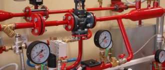
Heat supply can be regulated by turning off the taps on the radiators. In addition, you can entrust the regulation process to automation. Modern industry offers various devices that allow you to regulate the room temperature. The most common of them are radiator thermostats. These are devices consisting of a thermostatic head and a valve. The sensor measures the room temperature and controls the valve. Depending on the preliminary settings, the valve increases or decreases the flow of coolant, adjusting the heating level.
Thanks to the possibility of precise adjustment, this device allows you to regulate the microclimate inside the building, maintain a comfortable atmosphere, and save energy. There are different types of radiator thermostats. Most of them allow you to set the temperature value that the owner of the room wants to achieve. More complex models exist. Some of them allow you to set the temperature for different times of the day; for example, they can limit the heat supply during the day when there is no one in the apartment, and in the late afternoon they can warm the room to a comfortable level.
Waterproofing of pipeline passages
Pipeline waterproofing has its own characteristics and difficulties. When performing such work, it is necessary to take into account not only the strong water pressure from the outside, but also the response pressure of the internal liquids, as well as the constant temperature difference. Conventional sealants will not be able to withstand such a significant load for long. Therefore, for inlets, passages and pipeline entries, the principle of a three-component hydraulic seal is used.
This hydraulic seal consists of non-shrinking concrete mixtures and a polyurethane composition. The use of such a structure is especially effective in buildings where significant drying and movement of the structure is expected. The following are used as polyurethane fillers:
- "Aquidur TS-B"
- "Aquidur ES"
- "Aquidur TS-N".
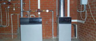
Unit characteristics and operating features
From the diagrams you can understand that the elevator in the system is needed to cool the overheated coolant. Some designs have an elevator, which can also heat water. This heating system is especially relevant in cold regions. The elevator in this system starts only when the cooled liquid is mixed with hot water coming from the supply pipe.
Scheme. The number “1” indicates the supply line of the heating network. 2 is the return line of the network. The number “3” indicates the elevator, 4—the flow regulator, and 5—the local heating system.
From this diagram you can understand that the unit significantly increases the efficiency of the entire heating system in the house. It works simultaneously as a circulation pump and mixer. As for the cost, the unit will be quite cheap, especially the option that operates without electricity.
But any system also has disadvantages, the collector unit is no exception:
- Separate calculations are required for each element of the elevator.
- Compression drops should not exceed 0.8-2 bar.
- Lack of ability to control high temperature.
Hot water supply in heating systems
DHW in multi-storey buildings is usually centralized, with water heated in boiler rooms. Hot water supply is connected from heating circuits, both single-pipe and double-pipe. The temperature in the hot water tap in the morning can be warm or cold, depending on the number of main pipes. If there is a single-pipe heating supply to an apartment building with a height of 5 floors, then when you open a hot tap, cold water will flow out of it first within half a minute. The reason lies in the fact that at night, rarely do any residents turn on the hot water tap, and the coolant in the pipes cools down. As a result, there is an overconsumption of unnecessary cooled water, since it is drained directly into the sewer.
Unlike a single-pipe system, in a two-pipe version, hot water circulates continuously, so the above-described problem with hot water does not arise there. True, in some houses, a riser with pipes is looped through the hot water supply system - heated towel rails, which are hot even in the summer heat. Many consumers are interested in the problem with hot water supply after the heating season has ended. Sometimes hot water disappears for a long time. The fact is that utility services are obliged to comply with the rules for heating apartment buildings, according to which it is necessary to carry out post-heating tests of heat supply systems (pro
Cost of sealing utility passages
The cost of waterproofing utility passages and the time frame for completing the work are determined individually in each case - they depend on the volume and complexity. Our specialists will be happy to come to your site at a time convenient for you to assess the current situation. They will choose the most optimal option for sealing technological openings, recommend certain materials for waterproofing, and draw up an estimate. We are always happy to help you!
The passage of the pipe through the foundation is carried out in accordance with SNiP standards. The technology for connecting the cottage's utility systems depends on the type of foundation:
According to the requirements of SNiP, the entrance of the pipeline to the building is insulated: waterproofing and thermal insulation.
- monolithic slab - first, two water supply lines and two sewerage pipelines are installed (one working, the other backup), then sleeves with pipes coming out of them are installed in the risers, and reinforced concrete is poured;
- — the technology is similar to the previous one, only the sleeves are mounted in the vertical walls of the base at a depth below the freezing mark;
- prefabricated strip foundation - technological gaps are left between the blocks, laid with red brick, into which sleeves/pipes are embedded.
What types are there?
The ITP classification is based on criteria that determine the characteristics, layout, purpose, and method of installation of a modular installation. A central heating point is an installation whose operation extends to several real estate objects. As a rule, it is installed in a basement or separate room. There are also:
- individual TP (serves one building or part of it);
- block TP (supplied assembled, compact, simplifies the process of updating utilities).
Diagrams of thermal units
If we talk about the schemes of heating points, it should be noted that the most common types are the following:
Thermal unit is a circuit with a parallel single-stage hot water connection. This scheme is the most common and simple. In this case, the hot water supply is connected in parallel to the same network as the heating system of the building. The coolant is supplied to the heater from the external network, then the cooled liquid flows in the reverse order directly into the heat pipe. The main disadvantage of such a system, compared to other types, is the high consumption of network water, which is used to organize hot water supply.
Diagram of a heating point with a sequential two-stage connection of hot water. This scheme can be divided into two stages. The first stage is responsible for the return pipeline of the heating system, the second - for the supply pipeline. The main advantage of thermal units connected according to this scheme is the absence of a special supply of network water, which significantly reduces its consumption. As for the disadvantages, this is the need to install an automatic control system to configure and adjust the heat distribution. This connection is recommended to be used if the ratio of the maximum heat consumption for heating and hot water supply is in the range from 0.2 to 1.
Thermal unit is a circuit with a mixed two-stage connection of a hot water heater. This is the most universal and flexible connection scheme. It can be used not only for normal temperature schedules, but also for elevated ones. The main distinguishing feature is the fact that the heat exchanger is connected to the supply pipeline not in parallel, but in series. The further principle of the structure is similar to the second scheme of the heating point. Thermal units connected according to the third scheme require additional consumption of network water for the heating element.
Errors and problems
To save money, many simplify the design, excluding important elements. But this should not be done for the following reasons:
- With closed radiators and a functioning heated floor, the boiler and heat pump pumps will interfere with each other’s operation.
- When radiators and floor heating are operating, the floor pump can reduce the pressure, thereby reducing the circulation of water in the radiators.
- Even when the boiler equipment is stopped, the TP pump moves liquid through the boiler and radiators, which is impractical. And if unnecessary movement of the coolant in the batteries can be dealt with by installing a check valve, then it will not be possible to stop the movement of water flows in the boiler.
- The absence of a protective thermostat can cause failure of the mixing unit, excessively hot water will enter the floor pipes, and there is a risk of damage to the screed.
- In the absence of a bypass valve, if the floor loops are closed, the circulation of liquid in them stops. Moreover, if you forget to turn off the pump, then it works on a closed valve and heats up, which leads to rapid failure.
You may not need to install a bypass valve if:
- one floor contour will be constantly open;
- the pump has frequency regulation;
- TP automation can control the circulation and, if necessary, turn off the equipment.
If you decide to heat a private house using a combined heating system - warm floors and radiators, you should familiarize yourself with all the diagrams, their pros and cons. Only then, you need to move on to choosing a model in accordance with your requirements, financial capabilities and characteristics of the room.
How the thermal unit works
In general, the technical structure of each heating point is designed separately depending on the specific requirements of the customer. There are several basic schemes for the design of heating points. Let's look at them one by one.
Thermal unit based on an elevator.
The scheme of a heating point based on an elevator unit is the simplest and cheapest. Its main drawback is the inability to regulate the temperature of the coolant in the pipes. This causes inconvenience for the end user and a large overconsumption of thermal energy in the event of thaws during the heating season. Let's look at the figure below and understand how this circuit works:
In addition to what is indicated above, the thermal unit may include a pressure reducer. It is installed on the feed in front of the elevator. The elevator is the main part of this scheme, in which the cooled coolant from the “return” is mixed with the hot coolant from the “supply”. The operating principle of the elevator is based on creating a vacuum at its output. As a result of this vacuum, the coolant pressure in the elevator is less than the coolant pressure in the “return” and mixing occurs.
Thermal unit based on a heat exchanger.
A heating point connected through a special heat exchanger allows you to separate the coolant from the heating main from the coolant inside the house. The separation of coolants allows for its preparation using special additives and filtration. With this scheme, there are ample opportunities to regulate the pressure and temperature of the coolant inside the house. This allows you to reduce heating costs. To have a clear idea of this design, look at the figure below.
The mixing of coolant in such systems is done using thermostatic valves. In such heating systems, in principle, aluminum radiators can be used, but they will last for a long time only if the coolant is of good quality. If the PH of the coolant goes beyond those approved by the manufacturer, then the service life of aluminum radiators may be greatly reduced. You cannot control the quality of the coolant, so it is better to play it safe and install bimetallic or cast iron radiators.
DHW can be connected in a similar way via a heat exchanger. This offers the same benefits in terms of hot water temperature and pressure control. It is worth saying that unscrupulous management companies can deceive consumers by lowering the hot water temperature by a couple of degrees. For the consumer, this is almost unnoticeable, but on a household scale it allows you to save tens of thousands of rubles per month.
Single pipe heating system
Single-pipe heat supply to an apartment building has a lot of disadvantages, the main one being significant heat losses during the transportation of hot water. In this circuit, the coolant is supplied from the bottom up, after which it enters the batteries, gives off heat and returns back to the same pipe. Hot water first reaches the end consumers living on the upper floors in a barely warm state. There are cases when a single-pipe system is further simplified, trying to increase the temperature of the coolant in the radiators. To do this, the battery is cut directly into the pipe. As a result, it seems that the radiator is its continuation. But only the first users of the system receive more heat from such a connection, and the water reaches the last consumers almost cold (about
Commissioning of the metering unit. Adjacent heating networks, jumpers
Resource supply for housing and communal services > Heat supply > Commercial metering of thermal energy. Resolution 1034
RULES FOR COMMERCIAL ACCOUNTING OF THERMAL ENERGY AND COOLANT
Commissioning of a metering unit installed at the consumer, on adjacent heating networks and on jumpers
61. The installed metering unit, which has undergone trial operation, is subject to commissioning.62. The commissioning of a metering unit installed at a consumer is carried out by a commission consisting of the following: a) a representative of the heat supply organization; b) a representative of the consumer; c) a representative of the organization that installed and adjusted the metering unit being put into operation.63. The commission is created by the owner of the accounting center.64. To put the metering unit into operation, the owner of the metering unit submits to the commission a draft metering unit, agreed upon with the heat supply organization that issued the technical specifications and the passport of the metering unit or a draft passport, which includes: a) a pipeline diagram (starting from the balance sheet boundary) indicating the length and diameters of pipelines, shut-off valves, instrumentation, mud traps, drains and jumpers between pipelines; b) certificates of verification of instruments and sensors subject to verification, with valid verifier marks; c) database of setting parameters entered into the measuring unit or heat calculator ;d) a sealing scheme for measuring instruments and equipment included in the metering unit, excluding unauthorized actions that violate the reliability of commercial metering of thermal energy and coolant; e) hourly (daily) statements of continuous operation of the metering unit for 3 days (for facilities with hot water supply - 7 days).65. Documents for putting the metering unit into operation are submitted to the heat supply organization for consideration at least 10 working days before the expected day of commissioning.66. When accepting the metering unit into operation, the commission checks: a) compliance of the installation of the components of the metering unit with the design documentation, technical specifications and these Rules; b) availability of passports, certificates of verification of measuring instruments, factory seals and stamps; c) compliance of the characteristics of measuring instruments with the characteristics, specified in the passport data of the metering unit; d) compliance of the measurement ranges of parameters allowed by the temperature schedule and the hydraulic operating mode of heating networks with the values of the specified parameters determined by the contract and the conditions of connection to the heat supply system.67. If there are no comments on the metering unit, the commission signs the act of commissioning the metering unit installed at the consumer.68. The act of commissioning a metering unit serves as the basis for maintaining commercial accounting of thermal energy, coolant using metering devices, monitoring the quality of thermal energy and heat consumption modes using the received measurement information from the date of its signing.69. When signing the act of commissioning the metering unit, the metering unit is sealed.70. The sealing of the metering unit is carried out by: a) a representative of the heat supply organization if the metering unit belongs to the consumer; b) a representative of the consumer who has the metering unit installed.71. Places and devices for sealing the metering unit are prepared in advance by the installation organization. The connection points of primary converters, connectors of electrical communication lines, protective covers on the settings and adjustment controls of devices, power supply cabinets for devices and other equipment, interference with the operation of which may lead to distortion of measurement results, are subject to sealing.72. If members of the commission have comments on the metering unit and identify deficiencies that impede the normal functioning of the metering unit, this metering unit is considered unsuitable for commercial metering of thermal energy and coolant. In this case, the commission draws up a report on the identified deficiencies, which provides a complete list of identified deficiencies and deadlines for their elimination. The specified act is drawn up and signed by all members of the commission within 3 working days. Re-acceptance of the metering unit for operation is carried out after complete elimination of the identified violations.73. Before each heating season and after the next verification or repair of metering devices, the readiness of the metering unit for operation is checked, about which a report on the periodic inspection of the metering unit at the interface of adjacent heating networks is drawn up in the manner established by paragraphs 62 - 72 of these Rules.
_______________________________________
Hermetic partition of the heating main. Sealing of utility inputs
Insufficiently high-quality waterproofing of the points of entry of various engineering communications, in particular, pipes and cables, is one of the most common mistakes of builders and designers. Due to the fact that the so-called cold seam remains in the “concrete-metal” or “concrete-plastic” joints, water enters through them into the basement recessed rooms
That is why it is very important to completely seal pipe entries using modern waterproofing technologies
Pipe entries are one of the most vulnerable places, since they are in direct contact with various building structures. If a leak occurs, significant damage may be caused to the entire building, walls and ceilings will be damaged. In addition, due to leaks, efflorescence and stains, fungus appear on the moistened surface of the walls, finishing coatings peel off, and all this invariably leads to additional costs for cosmetic repairs. To prevent this from happening, it is necessary to carry out sealing of pipe entries and communications in a high-quality and timely manner.
Sealing of pipe entries can be carried out at various stages, including:
- Sealing of pipe entries during the construction stage. For this purpose, various hydraulic spacers, waterstops and hydraulic cords can be used. The technology for sealing pipe entries in this way is carried out in the following sequence: before pouring concrete, a ring (or two rings) made of hydrophilic rubber is mounted on the pipe (end-to-end, without breaks or overlaps). The ring is attracted to the pipe or glued using a swelling sealant.
- Sealing of pipe entries at the installation and repair stage. There are several options for waterproofing joints, depending on the material from which the recessed part of the building is built. If these are FBS blocks, then the pipe entries are sealed in such a way that the hydraulic cord ring is in the middle of the wall thickness. If it is brickwork, then it is possible to seal the pipe entries by filling the hole in the wall with cement mortar. Regardless of the wall design, it is possible to waterproof the inputs using the injection method.
At whatever stage of the building’s operation you seal utility inlets (pipes, etc.), you cannot do without the use of special materials, such as hydraulic seals, swelling cords and sealants, multicomponent polyurethane and acrylate materials that can harden, bonding physically and chemically water, and do not allow unbound water to pass through.
When sealing pipes and communications, it should be remembered that the service life of wall structures exposed to moisture is greatly reduced due to corrosion of metal and concrete and destruction of bricks.
Therefore, it is very important to carry out waterproofing work in a timely manner.
One of the most vulnerable places of any communications is the place where a cable or wire enters the wall of a building, into a switchgear, actuator, etc. Today, there are many options for protecting cable passages from moisture, we have tried to collect the most effective of them for readers site in this article. So, let’s figure out now how cable entries into a building, ASU cabinet, etc. can be sealed.
What standards and requirements exist?
The regulatory documents PUE 2.1.58 and SNiP 3.05.06-85 describe the requirements for cable passages:
According to the requirements listed above, it turns out that the cable entry in the building must be able to retain water, not support combustion and prevent the spread of fire. With all this, it is possible to re-replace the cable or wire, if necessary.
Sealing methods
To seal the input in a private house or cottage, fire-resistant polyurethane foam is most often used, evenly distributing it in the pipe around the cable. After hardening, the polyurethane foam is cut and partially compacted, pressing it into the pipe. The resulting depression is plastered with cement mortar. An example of such a cable line sealing option is shown in the photo below:
Features of the combined system
The combined heating system includes radiators, which are high-temperature sources, and low-temperature sources - heated floors.
There are two ways to connect a water floor in a mixed scheme:
- To an existing heating boiler - this method reduces the cost of equipment and installation time. The disadvantage of this design is the inability to work autonomously. This increases energy consumption and reduces floor efficiency.
- By installing separate boiler equipment for the floor, this significantly increases installation costs. However, such a system has the advantage of being autonomous, its operation does not depend on batteries. This is convenient when radiator heating no longer functions.
There are several recommendations that should be taken into account when deciding to create shared heating in a private house:
- Set temperature conditions separately for radiators and heated floors. Since in batteries the heating of water at the supply and outlet is about 70 and 55 degrees, respectively, and for heating floors 40 and 30 are required, the boilers are not able to cope with this task on their own.
- Use special components to adjust heating. Pumping and mixing units, shut-off valves - they will reduce costs and allow you to correctly connect the system with the container in which the water is heated.
- Configure the combined system using special and correctly installed technical means. For example, a mixing unit with a thermostatic head, its function is to regulate the heating level of the liquid; the thermostat is responsible for controlling the degree of heating of each room individually.
When laying a water floor, there is no point in limiting yourself to only the bathroom and toilet. It is better to place such a system wherever possible, since increasing its area does not significantly affect installation and operating costs.
Indeed, in any case, you will need to install a mixing unit and a device that will ensure liquid circulation. It doesn’t matter what the collector group will be - one-pipe, two-pipe or more.
The cost of screeding also does not change, even if the floor is installed in only one part of the room, the concrete solution will have to be poured over the entire area.
Setting the return and supply temperatures in an apartment building
Installation of the heating system regulator will depend on its general structure
. If the CO is installed individually for a specific room, the improvement process takes place due to the following factors:
- the system operates from an individual boiler
; - a special three-way valve
was installed ; - The coolant
is
forcibly
.
In general, for all COs, work on adjusting the power will consist of installing a special valve
on the battery itself.
With its help you can not only regulate the heat level
in the necessary rooms, but also
to eliminate the heating process altogether in those areas that are poorly used
or do not function.
There are the following nuances in the process of adjusting the heat level:
- Central heating systems, which are installed in multi-storey buildings
, are often based on coolants, where
the supply occurs strictly vertically from top to bottom.
In such houses, it is hot on the upper floors and cold on the lower floors, so it will not be possible to adjust the heating level accordingly. - If houses use a single-pipe network
, then heat from the central riser is supplied to each battery and returned back, which ensures uniform heat on all floors of the building.
In such cases, it is easier to install heat control valves - the installation takes place on the supply pipe
and the heat continues to spread evenly. - For a two-pipe system,
two risers are already installed - heat is supplied to the radiator and in the opposite direction, respectively, the adjustment valve can be
installed in two places - on each of the radiators.
Types of Battery Control Valves
Modern technologies are far from standing still and make it possible to install a high-quality and reliable faucet
, which will control the heat and heating levels. It is connected to the battery with special pipes, which does not take much time.
Based on the types of adjustment, I distinguish two types of valves
:
- Conventional thermostats with direct action.
Installed next to the radiator, it is a small cylinder, inside of which
a siphon based on liquid or gas
, which quickly and competently responds to any temperature changes.
If the temperature of the battery rises, the liquid or gas in such a valve expands, causing pressure on valve stem
, which will move and block the flow. Accordingly, if the temperature drops, the process will be reversed.
Photo 1. Diagram of the internal structure of the thermostat for the battery. The main parts of the mechanism are indicated.
- Thermostats based on electronic sensors.
The principle of operation is similar to conventional regulators, only the settings differ - everything can be done not manually, but electronically - set the functions in advance, with a possible time delay and temperature control.
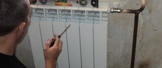
How to adjust heating radiators
The standard process for regulating the temperature of heating radiators consists of four stages
— bleeding air, adjusting pressure, opening valves and pumping coolant.
- Bleeding air
.
Each radiator has a special valve, by opening which you can release excess air and steam that interferes with the heating of the battery. Within half an hour
after this procedure, the required heating temperature must be reached. - Pressure adjustment
. To ensure that the pressure in the CO is distributed evenly, you can turn the shut-off valves of different batteries attached to the same heating boiler to different numbers of revolutions. This adjustment of the radiators will allow you to heat the room as quickly as possible. - Opening valves
.
Installing special three-way valves
on radiators will allow you to remove heat from unused rooms or limit heating, for example, while you are away from the apartment during the day. It is enough to simply close the valve completely or partially.
Photo 2. Three-way valve with thermostat, allowing you to easily adjust the temperature of the heating radiator.
- Coolant pumping.
If the CO is forced, the coolant is pumped using control valves, with the help of which a certain amount of water is drained to give the heating radiator the opportunity to heat up.
How does the process of heating a high-rise building take place?
Each apartment building has a central heating system, which consists of the following elements:
- source;
- heating network;
- consumer.
Boiler houses and thermal power plants act as sources of thermal energy.
From boiler rooms to houses, hot water is sent immediately and requires a decrease in temperature, otherwise the heating equipment of the house will be damaged. In a thermal power plant, it is converted into steam to produce electricity, then this steam is used to heat the coolant entering the heating network of the building.
Dependent circuit with three-way valve and circulation pumps
Dependent diagram for connecting a heating point of a heating system to a heat source with a three-way valve for a heat flow regulator and circulation and mixing pumps in the supply pipeline of the heating system.
This scheme in ITP is used subject to the following conditions:
1 The temperature graph of the heat source (boiler room) exceeds or is equal to the temperature graph of the heating system. A heating point connected according to this principle diagram can operate either with or without an admixture to the supply flow from the return pipeline, that is, to let the coolant from the supply pipeline of the heating network directly into the heating system.
For example, the calculated temperature graph of a heating system is 90/70°C, equal to the temperature graph of the source, but the source, regardless of external factors, always operates with an outlet temperature of 90°C, and for the heating system, it is necessary to supply coolant with a temperature of 90°C only at the calculated temperature. outside air temperature (for Kyiv -22°C). Thus, at the heating point, the cooled coolant from the return pipeline will be mixed with the water coming from the source until the outside air temperature drops to the calculated value.
2 The heating point is connected to a free-flow collector, hydraulic arrow or heating main with a pressure difference between the supply and return pipelines of no more than 3 m of water column.
3 The pressure in the return pipeline of the heat source in static and dynamic modes exceeds the height from the point of connection of the heating point to the top point of the heating system (building static) by at least 5 m.water.st.
4 The pressure in the supply and return pipelines of the heat source, as well as the static pressure in the heating networks, do not exceed the maximum permissible pressure for the heating system of the building connected to this ITP.
5 The heating point connection diagram must ensure automatic high-quality regulation of the heating system according to a temperature or time schedule.
Description of the operation of the ITP circuit with a three-way valve
The principle of operation of this scheme is similar to the operation of the first scheme, with the exception that the three-way valve can completely shut off the selection from the return pipeline, in which all the coolant coming from the heat source without admixture will be supplied to the heating system.
If the supply pipeline of the heat source is completely blocked, as in the first scheme, only the coolant that comes out of it, taken from the return, will be supplied to the heating system.
Dependent circuit with three-way valve, circulation pumps and differential pressure regulator.
It is used when the pressure drop at the point of connection of the ITP to the heating network exceeds 3 m of water column. The differential pressure regulator in this case is selected to throttle and stabilize the available pressure at the inlet.
Diagrams and installation instructions for one boiler
The simplest and most economical way to build a combined heating system in a private house is considered to be a scheme with a radiator and heated floor from one boiler. All elements and the circulation pump are already installed from it.
There are wall-mounted boilers that already have a pump built into them. When using a floor-standing model, it will have to be installed separately.
When directly connected to a gas appliance (this is the model that experts recommend installing when installing a combined heating method in private homes), it is recommended to install a container for condensate. Installing a conventional gas boiler will lead to rapid failure of the heat exchanger.
Gas equipment is placed in rooms with ceilings of at least 2 meters. Ventilation is required.
If a solid fuel model is used, then to connect the heated floor to it, you need to install a buffer tank. Its function is to limit the temperature regime, since it is difficult to directly regulate the temperature.
The principle of operation of heating according to a combined scheme - warm floor and battery from one boiler is as follows. The heated water is directed to the mixing unit, where it rests against the safety head. The thermal head determines its temperature, and if it exceeds the required level, the valve opens and the hot and cold coolant is mixed to the required degree.
Then the water is distributed along the contour lines of the floor and radiators. After passing through the entire pipeline, it returns to the heat generator for heating.
The connection diagram for underfloor heating and radiators from one boiler includes the following elements:
- boiler with expansion tank - heats the coolant;
- hydroarrow - wiring, in the form of a pipe with four branches, through which water moves;
- radiator and sex pump - they supply fluid to the collector unit;
- collector - floor loops are connected to its outputs, and hot water is supplied;
- mixing unit - in it the coolant for the TP is diluted;
- thermostat - a head that opens or closes the flow of water into the circuits.
System installation
After constructing the floor “pie” - leveling the base, hydro and thermal insulation and laying the heating elements, you can proceed to installation work and connecting a combined heating system from one boiler (warm floor and radiators). Let's look at the process step by step:
- The boiler is installed and its piping is made (in a private house it is often installed in a separate building). The room must have a chimney and air flow.
- The pipes from the radiators are connected to the water heater, and a pump is mounted between them.
- The floor circuits are connected through a device in which the water is diluted to the required temperature. For this purpose, the following are used: a mixing unit, a 2- or 3-way valve, they are attached to the supply pipe.
- A circulation pump is installed.
- The floor contours are connected through a comb to a source of hot water; it is the coolant that will heat the room.
Heat supply and regulation with a two-pipe scheme
This option is more complex, but it allows you to significantly expand the capabilities of mechanisms for regulating the heat supply to each consumer
. The difference between the system is that the coolant that has given up part of the energy does not continue to move through the same pipe to the next consumer; it flows into the second pipe, the “return”. Thanks to this, the coolant has approximately the same temperature along the entire path, at each radiator.
It is this solution that makes it possible to regulate the heat supply in an apartment building
using each individual radiator. You can regulate the temperature either manually using a valve or automatically using thermostats.
Regardless of how the heat supply is implemented, the system must include devices for automatic metering and regulation of heat supply in an apartment building. This makes it possible not only to provide housing with the heat necessary for life, but also to significantly save energy resources.
In apartments or private houses, residents often encounter the phenomenon of uneven heating of radiators
heating in different parts of the home. Such situations are typical in cases where the premises are connected to autonomous heating systems.
How to optimize the system
heating (CO), stop overpaying and how installing a heat regulator for batteries will help - we’ll look at it further.
Radiators for heating systems of high-rise buildings
Cast iron radiators, which have previously been used for decades, are familiar to many residents of multi-storey buildings. If it is necessary to replace such a heating battery, it is dismantled and a similar one is installed, which is required by the heating system in an apartment building. Such radiators for centralized heating systems are considered the best solution, since they can withstand fairly high pressure without problems. The passport for a cast iron battery indicates two numbers: the first of them indicates the operating pressure, and the second indicates the test (pressure) load. Typically these values are 6/15 or 8/15. The higher the residential building, the greater the operating pressure. In nine-story buildings it reaches 6 atmospheres, so cast iron radiators are suitable for them. But when it is a 22-story building, then for the working functioning of centralized heating systems, 15 atmospheres will be required. In this case, steel or bimetallic heating devices are needed.
Experts do not recommend using aluminum radiators for central heating - they are not able to withstand the operating condition of the water circuit. Also, professionals advise property owners, when carrying out major renovations in apartments and replacing batteries, to change the coolant distribution pipes to ½ or ¾ inches. Usually they are in poor condition and it is advisable to install ecoplast products instead.
Some types of radiators (steel and bimetallic) have narrower water flows than cast iron products, so they become clogged and subsequently lose power. Therefore, at the point where the coolant is supplied to the battery, a filter should be installed, which is usually mounted in front of the water meter.