The pumping and mixing unit and the manifold group of the water heated floor are designed to regulate the circulation of the coolant in the circuits, control the pressure in the heating system, eliminate air pockets and control the temperature. How the manifold for a heated floor is assembled, the basic connection diagrams and common mistakes, we will consider further. You can read about the device and principle of operation here
Why do you need a heated floor collector?
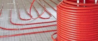
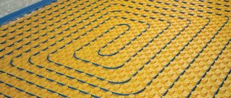
The “water heated floor” system is an effective way to uniformly heat all rooms in the house. Installation of this type of heating without a collector group is possible provided that a single circuit is laid. However, the maximum possible length of one pipe should not exceed 70 m, which effectively covers seven square meters. Thus, on average, a minimum of 2 circuits will be required per room.
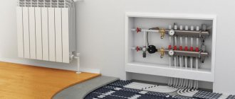
Pumping and mixing unit with a minimum number of circuits
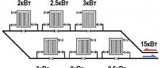
When laying water heated floors simultaneously in several rooms without turning on the collector, it will be impossible to regulate the main indicators of the correct operation of the heating system. The absence of a collection group is fraught with serious problems:
- Inability to regulate pressure in the heating system and bleed air;
- If the water heated floor pipe is damaged, you will have to turn it off completely in the entire house;
- Uneven heating of the premises of the house.
Improper functioning of the system will lead to costly repairs. If you have some skills, it is possible to install the unit without involving specialists. It is enough to purchase a manifold group that matches the parameters of the pumping and mixing unit and connect them in compliance with the technology.
Rules for installing the comb
The location for placing the collector block must be determined at the design stage of the house. As mentioned above, if this is a multi-storey cottage, then such units should be provided on each floor. It is best to prepare special niches for them, which are located above the floor level.
However, if it was not possible to find a place for the unit in advance, you can install this unit in any room where it will not disturb anyone: in the pantry, in the corridor or in the boiler room. As long as there is no excess moisture in this place.
To keep the unit out of sight, you can place it in a special cabinet, which is offered to their customers by manufacturers of locking mechanisms. The body of this cabinet is made of metal. It is equipped with a door, and its side walls have holes for heating pipes. Sometimes the collector group is simply placed in a niche or on the wall, securing the combs with special clamps.
This comb is placed in a place specially equipped for it. As you can see, it looks quite aesthetically pleasing, and most importantly, access to this node will not be difficult
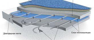
The pipes that extend from this distribution device are located in the walls or floor and are then connected to the heating radiators. If the pipes are located in the floor screed, the heating appliances should be equipped with an air vent or an air valve.
What does a heated floor manifold consist of?
The control system for a water heated floor is a combination of valves, sensors, actuators and other elements. The principle of operation of the collector is simple - the heated coolant passes through the circuits, cooling and returning to the starting point for reheating. The design mixes circulating liquid of different temperatures, which allows you to obtain optimal parameters for heated floors.
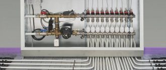
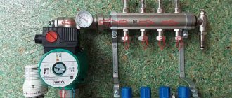
A standard mixing and distribution unit for a heated floor assembly consists of:
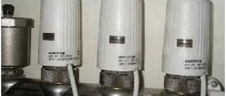
- Mixing unit (1) for diluting hot water from the boiler. Mixing occurs automatically due to the presence of temperature sensors and a servo drive used as a thermostat.
- Circulation pump (2) on the coolant supply pipe. The pump provides the system with the correct pressure to improve heating efficiency;
- Distribution comb (collector group) (3), equipped with outlets for connecting water circuits and flow meters for zonal distribution of circulating fluid through pipes. As well as a bypass (5) to prevent overheating of the pump.
INTERESTING: Plastic rings for wells: types, sizes and installation
Assembly of the collector unit
In addition, expensive models of collectors contain thermal sensors (4) that regulate the temperature depending on the temperature, and an air vent (4) for bleeding air plugs.
Design
A homemade manifold for heated floors consists of the following structural elements:
- 2 horizontal tubes with pipe outlets that are connected to the inlet and return. The supply pipe is equipped with branches that contain thermostatic valves. On the return there are bends with flow sensors.
- The parts are made of brass, stainless steel, and polypropylene elements.
- The thermostats have plastic caps for setting up the system; if you tighten them, the flow supply to the connected pipes is blocked.
- Flow meters make it possible to visually monitor the volume of water that circulates and adjust the hydraulic balance.
- Thermometer and pressure gauge - act as control elements for water floor manifolds. The pressure gauge is equipped with a release valve that will reduce the pressure.
- Additional elements are plugs and bends, brackets for fastening and taps, metal slats that need to be mounted in the cabinet.
- Additional circulation pump.
You can buy a similar kit assembled and install a heated floor collector without much time, but you can just as successfully create it from polypropylene with your own hands.
Accessories for water heated floors
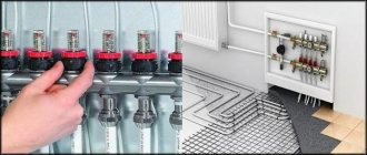
The complex design of the mixing unit and collector group is complemented by many auxiliary parts that play one or another role in regulating the operation of warm water floors:
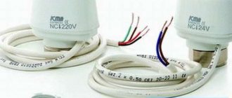
- The thermostatic valve is controlled manually or automatically using an electrothermal drive.
- Hydraulic balancing of the loops of the underfloor heating system occurs through tuning valves (there are options with or without flow meters).
- Ensuring constant pressure is achieved using an overflow valve, which redirects excess liquid to the bypass.
- The radiator balancing shut-off valve is used to open/close the water supply between the collector and the heating system.
- A bypass with a bypass valve, an expansion tank, a safety valve, as well as communicators and controllers are responsible for the trouble-free operation of water-heated floors and continuous monitoring of the operation of the heating system.
The mixing unit may have two or three way mixing valves. The first option is considered more reliable, as it allows you to limit the flow of water directly from the boiler using a balancing valve and thermostatic control units. This protects the circuit from exposure to boiling water, which is especially valuable when using polypropylene pipes.
The 3-way valve design is more versatile in terms of recommended heating area. Unlike two-way units, which cannot serve more than 200 m², a three-way valve creates optimal pressure in heated floors of any size.
Types and principle of operation
Collector devices differ in the material from which they are made - brass, plastic or stainless steel. And also by type of valve:
- With two-pass - the design feature is continuous heating of the coolant. Heated water is supplied continuously, and shut-off valves regulate its volume. As a result, the surface is heated evenly, while overheating of the system is not possible. But this model is not suitable for rooms whose area is more than 200 m2.
- With three-way - universal equipment, recommended for large rooms. According to the technology, installation with a servo drive is allowed (we suggest you learn more about servos in more detail) and various automation. The valve is capable of creating optimal operating pressure, adjusting the temperature level and the amount of coolant supplied.
Kinds
In addition, there are 4 types of collectors:
- Simple - a tube with shut-off valves, having internal and external threads. The model is cheap, but there is no function for setting up the system. To install such a collector on heated floors, additional elements are required.
- Equipped with valve outlets for adjustment, and valves for connecting circuits - a Chinese device. It is not uncommon for a structure to leak, but repairs are not difficult, just change the gasket. The distance between the supply and return pipes does not coincide with European standards, so various devices are required.
- With control valves and Eurocones - an expensive model. It does not have ball valves, but there are fittings and adjustment valves; a servo drive can be installed on them, which will regulate the temperature in the line.
- With flow meters - they are located on the supply pipe of the manifold, and on the return pipe there are sockets for servos. This device is intended for heated floors with circuits of different lengths; the presence of flow meters allows you to regulate the volume of coolant in each circuit.
Any model is equipped with outlets for draining water and air.
Principle of operation
The general principle of operation of the unit, regardless of the type of valve (two or three-way), is to distribute the flow of water along the loops of the heating floor, which circulates under the influence of the pump. The amount of coolant entering each branch is controlled mechanically or automatically by a servo drive.
The work process looks like this:
- Coolant heated to 60 - 80 degrees is supplied from the source to the comb through a thermostatic valve;
- A flow of chilled water from the return flow comes from the distributor;
- The shut-off valve has a head that regulates the temperature of the fluid;
- The mixed two streams are fed into the mixing pump, then the water is distributed through the pipelines.
When the heating temperature of the coolant in the main decreases to the required level, heated water from the source is mixed in, a two or three-way valve is responsible for this.
Assembly of the finished kit
The simplest and most reliable way, but more expensive, is to buy a ready-made set of pumping and mixing unit and manifold group. The assembly manual for the factory kit contains step-by-step instructions, allowing even an inexperienced craftsman to assemble it with his own hands.
Assembling a complete set of pumping and mixing unit and manifold group
The connection of underfloor heating pipes to the collector is made taking into account the throughput of the distribution combs and a drawn up diagram indicating the sizes of the pipes, their connection points with the elements of the heating system and the places of installation. Work on connecting the water circuit is carried out after installing the collector and protection system (bypass, air valve).
INTERESTING: PVC tiles: types and installation of vinyl tiles (step-by-step instructions)
At the end of the work, the connections are checked for leaks. To do this, the underfloor heating manifold with a flow meter is connected to the main pump, which pumps up the required pressure, and the system is left for 24 hours. If the set parameters have not changed during the day, the mixing unit can be safely operated. All inspections must be carried out prior to laying the final floor covering.
If you set out to assemble a water heated floor distribution system yourself, rather than buy a ready-made kit, then consider cheaper DIY design options.
From a profile metal pipe
Collector group from a profile pipe
Before manufacturing the collector, it is necessary to draw up a diagram with the location of all elements of the assembly. It is better to choose steel pipes with a square cross-section as the manufacturing material. This type is easy to process, which significantly reduces labor costs for installing pipes.
Manifolds made of profile pipes are used in the heating circuit of objects with a large number of circuits and a hydraulic separator. Square pipe parameters – 80*80 or 100*100 mm
The step-by-step process for producing a prefabricated distribution structure is as follows:
Assembling a collector from a metal profile pipe
Optimal temperature parameters
Setting up a water heated floor is carried out depending on individual needs. Some people like it when the room is warm, while others prefer invigorating freshness, even in the most severe frosts. But despite this, there are general standards that were developed taking into account sanitary standards, these include:
- floor heating up to 28 degrees;
- if there is another heat source or if you live indoors permanently, the ideal level is from 22 to 26 - these are optimal conditions for a person;
- if this type of heat source is the only one, or it is located in the bathroom, corridor, balcony, or in a house where people do not live permanently, it is permissible to raise the degree to 32.
Therefore, when regulating water floors, in addition to your preferences, so that the microclimate in the apartment is healthy, you should take these standards into account.
Manifold made of polypropylene pipes
If polypropylene pipes are used for production, you should pay attention to the presence of a reinforcing layer in them. In its absence, the plastic structure may be subject to deformation due to the current temperature conditions.
Detailed technical process for assembling the collector group:
Assembling a collector comb from polypropylene pipes
Mixing units made of polypropylene have an important advantage over their metal “counterparts” - low cost. Otherwise, you will have to come to terms with a number of shortcomings:
- Polypropylene manifolds are installed in systems with a small number of outlets (no more than 5 pieces);
- Flow meters cannot be installed;
- A larger protective box is required due to the massive structure;
- Be sure to have a set of specialized tools and soldering skills.
Assembling a distribution manifold from individual elements
For those who do not have special tools, you can assemble a comb from separate ready-made elements. It is better to select components from one manufacturer.
The circuits are connected according to the chosen scheme, adhering to the main rule - pipes with warm coolant are fixed at the top. Pipes with cooled coolant are secured from below.
At the final stage, it is necessary to carry out pressure testing and a control start-up of the heating in order to timely identify hidden or obvious deficiencies in the structure made.
Briefly about the main thing
The equipment of the collector block must meet the requirements for the functionality of the system. The collector device ensures uniform heating of the heating elements and a constant temperature in the room. Made from the following materials: polypropylene, brass and steel.
The manifold consists of a system to which threaded elements, fittings or control valves are connected. The collector is installed in a special cabinet or brackets are used.
Along with it, a mixing unit is used.
The durability of combs directly depends on the material and workmanship. You can purchase a ready-made distribution block or assemble it yourself from individual elements.
Tips for installing a warm water floor collector
Using a factory kit eliminates a number of common mistakes when installing a unit. The finished manifold group for underfloor heating is already equipped with the necessary valves and other important elements.
Be sure to consider the following recommendations:
- The calculation of the thermal load on the circuit is calculated before installation, and based on the data obtained, the balancing valve is adjusted;
- The cabinet for the mixing unit is placed in a place located at the same distance from the connected pipes;
- The dimensions of the collector box should be selected according to the dimensions of the device;
- Under the block, be sure to provide space for bending each contour;
- For a possible increase in water circuits, it is worth leaving several free pipes;
- The most efficient heating system is obtained by introducing a powerful circulation pump;
- When installing multiple pumps, be sure to use check valves.
INTERESTING: Adjusting water heated floors
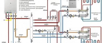
Diagram of pump-mixing and manifold assembly
Among other things, it is better to entrust the development of a heating floor collector circuit to professionals, even if you plan to assemble it yourself. The fact is that making accurate calculations without the appropriate knowledge is quite problematic. Saving on a qualified calculation of the parameters of the collector unit can lead to serious costs in the future.
Diagram with two-way valve
Install it on the supply from the heating device. A balancing adjustable valve is installed in the place of the jumper between the supply pipeline and the return line. It is adjusted in accordance with the required temperature of the supplied water, usually using a hex key. It is needed to regulate the amount of cold coolant.
The temperature sensor is placed after the pump, which in turn moves water in the direction of the comb. Only now the intensity of movement of the heated coolant from the boiler changes. In this way, the temperature of the supply water changes at the pump inlet, while the cold flow is adjusted and stable.
Mixing always occurs and water from the boiler does not enter directly into the circuits, since this is impossible. This scheme can be considered more reliable. But it should be noted that a mixing group equipped with a two-way element is capable of heating 150 - 200 “squares” of area, since there are no valves with greater capacity.