Types of boilers
Types of boiler equipment:
- gas. Highly effective, but not worth making at home. The units are classified as high-risk devices. Creation requires skills, technology;
A gas boiler
- electric boilers. Unpretentious in terms of creation and operation. You can make a heating device yourself. There are no increased security requirements;
- liquid fuel The design is simple. Any man can handle the job. Difficulty in adjusting the nozzles;
- solid fuel. Effective and versatile. Easy to use and manufacture. Easily modified and converted to other fuels. The units are also used for heating industrial areas.
It is important to choose the material from which the electric boiler will be made.
Heat-resistant stainless steel has good technical parameters. But she's expensive. Equipment is required to process the material. You can choose cast iron.
When making it yourself, it is better to take sheet steel or a pipe with a thickness of at least 4 mm. The properties of cast iron are good. Simple, easy to process. Regular household devices can handle it.
How to choose a thermostat
When visiting a specialized store, you should pay attention first of all to the following points:
- Connection.
- Mounting method.
- Functionality.
- Availability of Wi-Fi or GSM modules.
- Safety.
- Protection.
Most models can boast of good characteristics, the range of goods is also large, each owner can quite easily choose an item that will best satisfy his wishes.
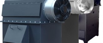
Features of electric boilers
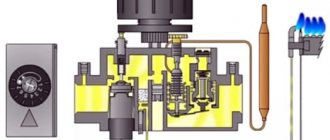
A special feature of the electric boiler is a heat exchanger with a heating element for heating water. A pump is used to organize forced circulation. There is an inlet for cold and an outlet for hot coolant.
Design
The operating mechanism of the heating unit is simple. Cold water is supplied to the heat exchanger. The heating element is heated by electric current. Thanks to the circulation pump, the liquid is distributed into the heating radiators.
What tools will you need?
To assemble homemade electric heating and encounter a minimum of difficulties, you must have high-quality tools at your disposal.
To work you will need:
Automation, electrics for manufacturing
The electrical part is responsible for the normal operation of boiler equipment. For operation, an electrical panel and three-phase input are assembled. The electrical panel is often metal. Comprises:
- toggle switch;
- machine;
- control buttons;
- relay;
- magnetic starter.
Automation is designed to simplify and conveniently control the unit. Responsible for equipment safety.
Automation
Sensors may be used. They are installed to maintain a comfortable microclimate according to specified parameters. If there are deviations from the normal operation of the heating system, the sensors turn everything off. Allows you to protect the owners and preserve property.
Easy adjustment of electric heating power
The closed or open position of the contacts depends on whether voltage is applied or removed from its control coil. It turns out that in order to assemble the automation, we must supply control signals (voltage) to the terminals of these same coils through some other elements.
The coil has two contacts A1, A2.
When purchasing, pay attention that starters can come with 380V and 220V coils. It's better to take the last option
In this case, you directly connect the neutral conductor to one of the contacts, and install microswitch buttons into the gap of the second.
What are they needed for? Thanks to them, you have the opportunity to turn on 1,2 or 3 heating elements alternately, thereby increasing or decreasing the heating power.
For example, the temperature outside the window is -5C. You press one button and start up just one heating element with a power of 2 kW. The frost hit -25C, press all three buttons and increase the power three times.
In this case, the number of heating stages will depend on the rated power of each heating element. If they are all 2 kW, that’s only three steps.
But if one is 2 kW, the second is 3 kW, and the third is 4 kW, then the number of stages automatically increases to seven!
Everything will depend on which phases (heating elements) are connected and in what sequence.
individually 2kW – 3kW – 4kW
together 2kw+3kw+4kw
separately 2kW+3kW
separately 2kW+4kW
separately 3kW+4kW
The current in the coil control circuits is very small (several milliamps). Accordingly, there is no need to install full-fledged switches here.
All these three microswitches must be supplied with one phase. Let's say phase C. Take it from the lower contacts of the input circuit breaker.
It is from this point that the entire further automation scheme begins.
What to consider when assembling the structure
The electric boiler must have a built-in electrical cabinet. It contains input, metering, protection, and control devices for the operation of the heating unit. A function is provided to switch operating modes of the heating system.
The electrical cable from the boiler equipment is inserted into the electrical panel. The boiler is connected to the inlet machine.
Depending on the area of the room, you need to calculate the power of a homemade electric boiler. For 1 sq. m of area accounts for 0.1 kW of thermal power of the heating device. To create a heating system for a house with an area of 100 square meters. m need to make a boiler with a capacity of 10 kW.
Thermal calculations for the house must be done immediately. The cross-section of the wire, elements of the boiler device, and automation depend on the power.
Laying the electrical cable around the house must follow safety rules. If the structure is made of wood, the cable is laid openly or in pipes. For buildings made of stone, brick, foam block, the wire is laid hidden or in boxes.
Homemade boiler
Any twisting, soldering, or welding not provided for by the design of the boiler equipment is prohibited.
The boiler requires strict compliance with safety measures.
Selection of input machine and starters
The circuit diagram of an electric boiler automation always begins with the supply of voltage through the input circuit breaker.
Electric heating usually implies the presence of a three-phase 380V input. This means that the machine must be three-pole.
Please pay special attention that this must be one three-pole switch, and not three separate single-pole ones. In the event of a short circuit and damage to the heating element of any phase, the protection must stop supplying voltage to all phases
In the event of a short circuit and damage to the heating element of any phase, the protection must stop supplying voltage to all phases.
After the introductory circuit breaker, the phase conductors need to be separated.
This is done using electromagnetic starters.
It is they who are responsible for the main work on automatic switching of the electrical network. You turn the machine on and off manually, and the starter will do this without your participation, based on the supply of control voltage from the corresponding sensors.
In this case, unlike an automatic machine, buy three separate single-phase modular starters. Old models such as PML, PMA, KMI will not work here. And the point is not at all in their noisy work and loud clicks.
A modular three-phase unit in a single housing will also not be suitable for our circuit.
The most important advantage of single-phase ones is the ability to manually and very simply adjust the power of the electric boiler. This will be discussed in more detail below.
The heating elements (heating elements, electrodes) of the heating boiler are connected to the power terminals of each contactor.
Step-by-step manufacturing instructions
Tools and materials should be at hand. You can get started:
- Take a cut piece of metal pipe. Cut threads on both sides. On one side, a coupling with electrodes is inserted, on the other, a plug.
- It is necessary to weld the threaded pipes. They will be fastening elements of the thermal communication system.
- Two bolts are welded to the pipe. The first is for the “neutral wire”, the second is for the ground loop.
- For coordinated operation of the resulting product with a common heating system, pipes are supplied to the nozzles.
- The electrode is connected to the phase wire terminal.
- The “neutral wire” terminal and ground wire are connected to the previously welded bolted connections.
- You can begin installing the pressure gauge and fuse system.
- After connecting the automation system, you can begin connecting to the panel.
Boiler installation:
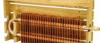
You can make your own electric boiler with heating elements. To do this, select a tank in which heating elements are installed. They are bought in the store. The quantity depends on the case and heating area. More often than not, two or three. The products include a threaded head.
The boiler body is a metal pipe. The supply and return pipes are soldered into the side. It is better to install heating elements from above to simplify replacement. There is no need to drain the water. To eliminate the problem of air accumulation, an automatic gas vent is provided.
Nuts are screwed onto the installed heating elements and welded. A pipe for draining water is installed at the bottom of the housing. The pipes are threaded. Allows you to connect heating system pipes to the electric boiler.
The unit is installed on the heating circuit and connected to the electrical network. Connecting the device to the panel or machine is identical. The device power is calculated.
Connecting heating elements star - triangle. Areas of application :: Elemag
Different types of tubular electric heaters (TEHs) can be connected to single-phase and three-phase networks. The electric heater can be connected to a three-phase network using one of two main schemes - “star” or “delta”. To distribute the load evenly in each phase, the number of heating elements must be a multiple of three.
For three-phase networks, heaters are used whose operating voltage is rated at 220 and 380 Volts.
Electrical appliances with an operating voltage of 220 Volts are connected according to the “star” circuit, and heaters with a voltage of 380 Volts are connected to the network according to the “star” and “delta” circuits.
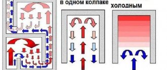
Star connections.
For example, let’s imagine a “star” circuit, which is made up of three electric heaters.
The second output (2) of each of the heaters is supplied with the corresponding phase. The first terminals (1) of the heating elements are connected together with the simultaneous formation of a common point, which is called zero or neutral. This type of load connection is a three-wire one.
It is advisable to use a three-wire connection at an operating voltage of 380 Volts. Below we propose to consider the installation diagram of a three-wire connection of heating elements into a three-phase electrical network. In this case, the supply and shutdown of voltage occurs thanks to three-pole circuit breakers.
In the presented diagram it can be seen that the terminals located on the right side of the electric heaters are connected to phases A, B and C, and the terminals located on the left are connected at the zero point. Between the terminals on the right and the zero point, the operating voltage is 220 Volts.
In addition to the described circuit, you can also use a four-wire one. When connecting using a four-wire circuit, it is assumed that a three-phase load with a voltage of 220 Volts is connected to the network. In this case, the inclusion of the zero point of the load is connected to the zero point of the power source.
In the diagram presented above, the right terminals of the tubular electric heaters are connected to the corresponding phases, and the left ones are closed at one point, which is connected to the zero bus of the power source. Between the zero point and the terminals of the electric heaters, the voltage will be 220 Volts.
If it is necessary to completely disconnect the load from the mains, automatic switches “3+N” or “3P+N” are used. Such machines turn on and off all available power contacts.
Laws that apply when connecting star-type heaters:
Between each phase and zero, the voltage will always be 220 Volts.
To each branch of the “star” you can connect several heating devices, which will be connected to each other in series or parallel order.
The total power of the connection is calculated from the sum of the powers of the three branches
The power of each individual branch must be the same as that of the other branches.
Delta connection
With a delta connection, the leads of the electric heaters are connected to each other in series order. According to the connection diagram of three tubular electric heaters, the connection is carried out in the following order: the first terminal of the heater No. 1 is connected to the first terminal of the heating element No. 2; the second terminal of device No. 2 is connected to the second terminal of device No. 3; the second terminal of heater No. 1 is connected to the first terminal of device No. 3. As a result of this connection, you should get three arms - “a”, “b”, “c”.
Then the corresponding phase is supplied to each arm: to arm “a” phase A, to arm “b” phase B, and to arm “c” phase C.
Laws that apply when connecting heaters of the “triangle” type:
Between any two phases the voltage is always 380 Volts.
Several tubular heaters can be connected to each branch, which will be connected to each other in series or parallel order.
The power of each branch must have the same values.
The total total power is the sum of the power indicators of all three branches.
The voltage in all diagrams is indicated when connected to a three-phase network with a voltage of 380 Volts.
The Elemag company has extensive experience in the production of heating systems. For any questions regarding the purchase or connection of electric heaters, please contact us by phone or email. Our specialists can advise you on choosing the appropriate connection for heating elements. We use STAR and TRIANGLE connections in the production of dry heating elements and traditional electric metal block heating elements.
Connecting the electric boiler to the panel
It is recommended to entrust the installation of the shield to a specialist. A metal shield and three-phase input are not enough to operate the heating device. The electrical appliance must be grounded. A separate ground wire must be connected to the electrical panel. Connection to the electric boiler is made through the panel.
Connection to the panel
Grounding must be checked by services every year. They issue a certified protocol certifying the reliability of the ground loop.
Connection recommendations:
- ensure reliable grounding to prevent electric current from penetrating the housing;
- The high power consumer must be connected directly from the current input to the house. The circuit can only be interrupted by an automatic device that turns off the electric boiler in the event of a malfunction;
- the cable is selected in accordance with the rated load of the boiler;
- shut-off valves, which are usually used when connected to other types of boiler equipment, must turn off the unit from the common heating circuit. This will be needed when performing maintenance or repair of the electric boiler.
You can make an electric boiler yourself. Any man can do it. But you don’t need to connect the heating unit or make adjustments. It is better to entrust the work to a master. To avoid collisions due to improper installation of the device. Otherwise, the unit will not work efficiently and will break down.
Automation for electric boiler:
Average score of ratings is more than 0
Share link
Comments There are no comments yet, but you could be the first...
Designation on electrical circuits
The transistor has an accepted designation: “VT” or “Q”. After the letters you need to indicate the position index. For example, VT 2. On old drawings you can find symbols: “T”, “PP” or “PT”, which are no longer used. The transistor is drawn in the form of certain segments indicating the electrode contacts. Sometimes they are circled. The direction of the electric current in the emitter area is indicated by a special arrow.
Scheme of operation of the simplest radio element
Based on their operating principle and structure, the following semiconductor triodes are distinguished:
- Field type;
- Bipolar;
- Combined.
They all have similar functionality and differ in operating technology.
Field
Such triodes are also called unipolar, because of their electrical properties - they flow current of only one polarity. This type is also divided into several types according to its structure and type of adjustment:
- Transistors with PN control transition;
- Elements with an insulated shutter;
- The same transistors of a different structure (metal-dielectric-conductor).
Important! An insulated gate has one distinctive feature - the presence of a dielectric layer between it and the channel. Diagram of an element with an insulated gate
Diagram of an element with an insulated gate
Another feature of field-effect transistors is low power consumption. For example, such an element can function for more than one year on one battery. Field radio elements are quite independent: they consume extremely little electricity. Such a device can operate for years on a AA battery or a small battery. This is what led to their widespread use in electrical circuits and devices.
Electron-hole transition
Bipolar
These elements got their name because they are capable of passing plus and minus electric charges through one passage channel. They also have low input impedance. Such devices work as signal amplifiers and switches. Thanks to them, you can connect a fairly strong load to the electrical circuit and reduce the effect of its resistance. Bipolars are the most popular active-type semiconductor devices.
The principle of operation of a bipolar transistor in a circuit
Combined
Combined elements are invented in order to achieve the required electrical parameters using one discrete state. They are:
- Bipolar with resistors embedded in their circuit;
- Two triodes of one or more structure structures in a single part;
- Lambda diodes - a combination of two field control triodes that create resistance with a minus sign;
- Elements in which field components control bipolar ones.
Combination transistor