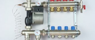
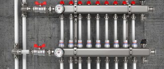
A manifold for underfloor heating is a distribution unit that redirects the coolant from the heating boiler through several circuits of the floor heating system. But depending on the configuration of the structure, it may also be assigned other functional tasks. For example, deaerating the system, adjusting the supply of coolant volumes and monitoring its flow using manual or automated flow meters. This actually ensures the maintenance of the required temperature in the heating circuits of the heated floor (HF).
Among heating system installers, due to the characteristic appearance of the collector, another slang designation for it is widespread - “comb”.
Picture 1.
Features of the operation of water heated floors
Water heated floors are used as the main or additional source of heat in private homes. The idea of this system is based on laying thermal circuits and pipelines with coolant circulating through them in the screed. The liquid is heated in a boiler and then distributed through floor loops in different rooms. The main feature of the operation of such a system is the need to maintain a low, uniform temperature across a large number of consumers. The coolant comes from the boiler heated to 60 - 70 degrees, such heat from the floors will be uncomfortable for residents. To reduce the temperature, a mixing unit is included in the system or RTL valves (reverse flow regulator) are installed.
The second feature of heated floors is associated with the uneven distribution of coolant throughout the system. The rooms have different areas, which means the contours will be of different lengths. Redistribution occurs at the collector.
Device with 3-way mixing valves
The three-valve manifold assembly is a design with the following characteristics:
- mixing of liquids with different temperatures occurs inside the valve;
Structure of a three-valve manifold - simultaneous supply of heated coolant from the boiler and liquid from the floor heating through the bypass is carried out;
- To regulate operation, a damper is placed inside the valve. It is installed perpendicular to the supply and return pipes. By changing its position, you can adjust the temperature of the coolant supplied to the floor heating;
- The disadvantage of this type of design is considered to be the presence of temperature surges. The advantage of 3-way valves is their versatility, as they are suitable for all types of water circuits.
What does the collector group consist of?
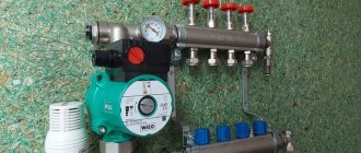
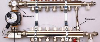
The collector has the form of a metal or plastic tube in which the coolant is collected and redistributed along the circuits. The collector group usually consists of two combs: supply and return, a pumping and mixing unit and additional equipment.
On the left is a pumping and mixing unit with a thermal head, on the right is a manifold comb with rotameters and a drain valve.
Collecting combs
The main differences between the supply and return combs are only in the shut-off valves. The heated coolant from the boiler comes to the supply, then the liquid is redistributed between the heating devices. The substance (water, ethylene glycol or propylene glycol) passes through the circuit, gives off heat and returns to the return comb, from where it goes back to the boiler.
Read more about choosing a coolant for a heating system in a separate article.
How it works?
The collector combs have a larger diameter compared to the pipes, because of this the coolant in the distribution block slows down its movement. Distribution occurs through pipes with a smaller flow. One comb can have up to 14 pipes, depending on the number of heating devices. Typically, the supply is equipped with adjusting devices to change the flow of underfloor heating circuits. More coolant will flow into a pipe with a higher throughput, and accordingly the heating devices will heat up more.
Shut-off valve options
To regulate the amount of coolant on the collector, ball valves, valves, flow meters (rotameters), thermostatic push-action valves or servos are used.
- Ball valves are shut-off valves with two positions: (open and closed), allowing you to stop the movement of the coolant through a separate pipe of the comb. Ball valves do not allow you to regulate the flow, so it makes sense to use them in heated floors, where the loops are approximately equal in length. They are also placed in front of collectors.
An example of a manifold with ball valves.
- The valves allow for stepwise changes in the flow diameter and require manual control of the system.
There are flow meters on the top of the supply comb, and thermostatic valves on the bottom of the return.
- Flow meter (rotameter) is a device that measures fluid flow per unit of time. It is a transparent flask with a stem inside; the mechanism of operation of the valves is similar to a regular valve.
The coolant flows along a shorter line with less hydraulic resistance - the flow meter on such loops narrows the passage, and on longer ones it widens it, due to this the floor in different rooms heats up equally.
- Thermostatic pressure valves are installed on the return comb of the underfloor heating manifold. They can close or open depending on the return temperature. The TSG valve is equipped with a Eurocone, which allows you to measure the temperature of the liquid in the pipe.
- Thermoelectric servo drive is a thermostatic head that can remotely control the operation of the comb valves. Servo drives are divided into normally closed and normally open. In the first case, in the normal position the valve is closed and opens when voltage is applied. The servo drive is connected to a thermostat, which is located in the room and responds to changes in air temperature.
The thermoelectric servo drive should not be confused with RTL valves. The first reacts to changes in room temperature, the second is adjusted to the temperature of the coolant.
Thermoelectric head with servo drive.
Types of floor heating systems
There are two fundamentally different systems; let’s look at their strengths and weaknesses. The choice of scheme will affect the comfort of living in residential premises, keep this in mind when making a decision, take into account not only the technical parameters of various schemes, but also the features of the premises and existing heating systems.
Water heated floor
Allows for uniform floor heating and is compatible with some existing heating systems in older buildings. Disadvantages include the complexity of equipment and installation work and the high estimated cost. In addition, the water system reduces the height of the room by at least 10 cm due to the concrete screed. To create an installation diagram, the room is divided into separate sections, taking into account the size and configuration of the floor; each circuit must have approximately the same length of pipes, otherwise the heating will be uneven over the area. Depending on the construction technology, a water floor can have several installation schemes.
- On a concrete base. It consists of a layer of thermal insulation on a concrete base, a metal mesh for laying pipes, pipelines, a top screed and a finishing floor covering.
- Polystyrene. A more modern method of laying a water-heated floor, there is no need to do a cement-sand screed. Special polystyrene plates with places for fixing plastic pipelines are laid on the thermal insulation layer. The finished wiring is covered with gypsum fiber boards, on which the finishing flooring is laid.
The general disadvantage of water floor heating is that emergency situations have very serious consequences. The most complex elements of a water heated floor are the mixing unit and the manifold.
Description of types of mixing units
The mixing unit ensures constant and balanced circulation of heated water along the laid circuits, changes the speed of movement, and independently maintains the set temperature of heating the floor and coolant. Depending on the design features, it can have several types:
- with series connection of water pump and two-way thermal valve;
- with series connection of water pump and three-way thermal valve;
- with a series connection of a water pump, a three-way thermal valve operates with flows converging in one unit;
- with parallel connection of a water pump, two-way thermal valve;
- the water pump is connected in parallel, the thermal valve is three-way.
Mixing unit for heated floors
Each scheme has its own characteristics; selection is carried out taking into account technical parameters and the number of heating circuits.
Piping for radiators and heated water floors
Distribution manifolds
Designed to connect all heating devices of the floor heating system in one place. Depending on the nomenclature and quantity of additional special equipment, they can be simple or advanced. Simple ones do not have any fittings and serve only to connect fittings. Advanced ones have control sensors, execution devices, measuring instruments, etc.
Should I assemble a collector or buy a ready-made one?
Collectors can be prefabricated, ready-welded or homemade. Let's consider their advantages and disadvantages.
Ready welded
They are usually produced in the form of supply and return combs welded together with a specified number of pipes.
Advantages
- Fast installation - no need to assemble fasteners.
- Minimum qualification requirements for an installer
Flaws
- Difficult to configure for a specific system.
- The number of pipes may not meet the needs, in which case they will have to be blocked off with plugs and not used.
- The collector can be equipped with elements that are unnecessary for a particular heating system. For example, it may have a hydraulic distributor (hydraulic arrow), which is only useful in networks with a large number of pumps.
- The return and feed combs may be welded together, making it difficult to attach separate loops to them. The pipes on factory mixers are usually located at the same distance from each other, but this is not always convenient.
Homemade
You can make a collector with your own hands from available materials: steel pipes with a round or square cross-section. To do this, holes are cut in them and pipes are welded. Couplings are made from round sections of smaller diameter.
Advantages
- Making a collector with your own hands is profitable from a financial point of view.
- You can make a drawing and manufacture an individual manifold for a specific system.
Flaws
- To perform this job, you will need skills in working with a welding machine.
- It will take more time.
- The non-separable design makes it difficult to repair and replace individual elements.
Prefabricated
Such distribution units are assembled from factory parts, which are purchased separately or as a kit. They will be discussed further.
Advantages
- There is variability when designing a collector unit for a specific heating system.
- Does not require special skills or equipment for installation.
- Possibility of separate dismantling of feed and return combs.
- High installation speed.
Flaws
- Components from different manufacturers may not fit together.
- This option usually costs more.
Valve selection based on parameters
Both two-way and three-way valves are characterized by throughput (performance). This value means the volume of coolant that the device is capable of passing per unit of time, expressed in liters per minute or cubic meters per hour.
In the process of designing a heating system, it is necessary to make appropriate calculations of the main parameters. But when assembling a manifold for a heated floor with your own hands, such calculations are rarely performed.
Typically, experimental indicators are taken as a basis:
- valves with a capacity of up to 2 cubic meters per hour can provide heating of 50-100 “squares” of area;
- if the throughput is from 2 to 4 cubic meters per hour, such valves are mounted on systems with floor heating up to 200 “square”;
- when the area is over 200 square meters, 2 mixing units are often installed.
If you want to assemble a manifold for a heated floor with your own hands, for greater reliability you need to take only branded and proven elements. This is important because the operation of the entire structure depends on it.
When thinking about which collector to choose for a heated floor, you must also pay attention to the limits for adjusting the heating temperature of the coolant. The manufacturer's instructions usually indicate the minimum and maximum temperatures.
How to install a rotameter on a manifold comb
Rotameters are often used on underfloor heating manifolds; they are necessary to control flow. Depending on the model, the device can be adjusted to different flow rates from 0 to 5 l/min. The setting is made only when the pump is turned on. It is necessary to remove the decorative protective cap and tighten the fixing nut into the desired position. After setting up the flow meter, the plug is installed in place.
Rotameters differ for the return comb and the feed comb. Inside the glass flask of the device there is a rod with a plate. In the non-working state, the rod plate is pressed to the zero value by a spring. The coolant is always supplied under the valve seat, since the flow opens the valve. On reverse rotameters the rod is at the bottom, and on feed rotameters it is at the top (the numbers will increase from above).
Differences between the rotameter on the feed and return combs.
If you confuse the supply and return rotameter, the coolant flow will press the rod against the seat, and the system will not work. Some devices do not allow you to record the required flow rate, but only measure its value; to distribute flows along the contours of heated floors, it is advisable to use the first option.
Selection and ordering of equipment
Tigrohause is a direct supplier, guaranteeing quality on behalf of the manufacturer. The catalog of our online store contains devices from reliable manufacturers Mixell, Thermotech:
- with two straight ball valves;
- with one straight and one angle ball valve;
- with two angle ball valves.
To select and buy a suitable, inexpensive distribution manifold for a heated floor, it is no longer necessary to personally visit the point of sale. Just go to the catalog page and place your order online.
Having trouble choosing? Consult with store consultants. Our experts will guide you on the optimal equipment, including helping you decide on distribution combs: they are available for sale with a different number of outputs and connection diameters. There are models for servicing from 2-12 circuits.
Mixing unit
The mixing unit can be used without a collector.
The mixing unit is often included in the collector group. Its operating principle is based on combining the supply and return flows. After passing through the heated floor loop, the medium usually has a temperature of about 30 degrees; at the mixing unit it flows into the supply flow, which allows you to get a comfortable temperature of 40 degrees.
There are many options for implementing this unit: using a three- or two-way valve, using thermostatic valves, etc. Mixers can also be prefabricated or factory-made.
The mixer usually has a thermostatic valve that measures the temperature of the medium. It is equipped with an overhead or cap sleeve. The first is simply glued to the pipe, the second is inserted into the line itself.
A three-way valve with a thermal head is installed in front of the pump. It is also useful to install a coarse filter on the supply before it.
- A three-way valve is installed on the supply side; using a thermostatic head, the element allows you to control two flows. There are mixing valves and distribution valves. The first one receives two streams from different sources, combines them into one and sends them along the required highway. The distribution valve receives one flow, which is distributed through several circuits. These elements are used not only to regulate the temperature of the coolant, but also to protect the boiler to prevent idling and overheating. However, the valve installation and layout will not be the same as when used in combination with a manifold.
A mixer with a two-way valve; on the bypass it is useful to install a hidden valve under a hexagon instead of an element with a handle.
Bypass is a channel between the return and supply combs; it creates a small circle and prevents the pump from working at a dead end when one of the lines is closed.
- The two-way valve is equipped with a thermostatic head and controls the flow in only one direction. When using this element in a mixing unit, an additional bypass valve will be required. In most cases, shut-off valves are placed under the hexagon. Ball valves cannot be used on this unit due to the impossibility of precise adjustment; it is also not recommended to install a valve with a handle, since someone could accidentally mess up the entire system setting.
The mixing unit is installed after the collector. A pump is placed between the collector and the boiler, which ensures movement in a small circle. The three-way mixing valve is installed on the supply line, the distribution valve - on the return line.
Location of two-way and three-way valves in the heating system
| Task | Two way valve | Three-way valve (distribution) | Three-way valve (mixing) |
| Boiler protection | — | Innings | Return |
| Temperature regulation | Innings | Return | Innings |
The mixing unit on a two-way valve can always be distinguished from a three-way valve by the presence of a valve on the bypass.
Adjusting the operation of the mixer using the example of a two-way valve
In a three-way valve, the flow is always open: if one plug closes, the other opens. In a mixer with a two-way shut-off device, only one plug closes; it works as follows: the thermal head determined that the temperature of the medium is lower than necessary, pressed the rod, the valve opened, and a portion passed into the manifold, mixing with the liquid from the return. When the temperature has reached the required values, the thermal head begins to close: the flow from the supply decreases, the flow from the bypass increases.
- The longer the heating circuit of the floor, the more the bypass valve is closed.
The bypass valve has a hidden valve for a hex key. When setting up the system, you need to close the thermostatic valve and open the balancing valve. The rotameters are adjusted, then the valve on the bypass is gradually closed until the rotameter rod begins to show that the coolant is becoming less. Fully open the thermostatic valve and tighten the balancing valve again. As soon as the rotameter plates lower or rise when turning the key on the bypass valve, balancing stops.
Balancing contours and filling screed
Next, hydraulic balancing of the individual underfloor heating circuits occurs. To do this, you need to use a special adjustment key to set the value specified by the designer on the fine adjustment valves.
If you do not have such valves, then set the calculated coolant flow for each heating circuit. This is done with flow meters.
They set the flow in order to align all the contours with each other. After all, each can be any length, and your coolant must flow evenly along all circuits, and not just along the shortest one.
After pressure testing and checking for leaks, the pipes are filled with screed. In this case, the system must be filled with cold water and be under pressure.
Mistake #6 - pouring screed with empty pipes.
When the screed gains strength, thermal tests are carried out. This takes a period of time equal to 7 days.
In this case, during the first three days, the heating system is flushed with water at a temperature of 20 degrees. Over the next 4 days, the maximum operating temperature is set and the heating of all circuits is checked.
Thermal testing is also documented in a protocol.
Do you need a hydraulic gun?
A hydraulic separator (hydraulic arrow) is a device that is usually placed between the boiler and the collector; it provides zero resistance in this area. Visually, the element is a hollow pipe with 4 pipes: on one side, two are intended for the boiler, on the other, for the collector. The question of installing a hydraulic separator arises when there is a need to install more than 4 pumps and more than 1 boiler.
The hydraulic arrow can be fixed vertically or horizontally, it does not matter. The first option is often chosen, as it simplifies the installation of the air vent in the upper part. A tap can be attached to the bottom to remove sludge.
Often in articles this device is attributed properties that it does not possess. We list the tasks for which you should not buy a hydraulic gun.
- Does not increase boiler efficiency
- Does not reduce fuel costs
- Does not protect against heat stroke
- You still need to select pumps for each circuit separately.
- Not intended for air bleeding or sludge protection.
The hydraulic arrow can worsen the operation of the system if the pumps are incorrectly selected. For example, a boiler unit is much inferior to the total power of devices on other circuits. As a result, the coolant reaches the comb already cold due to mixing with the reverse flow.
Are a manifold and mixing unit required?
In a small house, a heated floor may not take up so much, in which case the costs of a collector and mixer will not be worth it. The simplest solution would be to install a heated floor with one or two circuits, controlled by a TSG thermal head or an RTL tap. Regulation in this circuit occurs by limiting the temperature on the return flow.
The RTL valve is not intended for installation on a manifold; it has high hydraulic resistance. Due to the large size of the head, it is inconvenient to screw the element onto a distribution unit with a large number of adjacent circuits. This also makes it impossible to use built-in plumbing cabinets. It is not recommended to install RTL cranes on a circuit longer than 70 meters. The thermal head is usually placed in a plastic box that is hung on the wall.
The TSG head also limits the return flow, but has a Eurocone, so it can be installed on the return of the manifold. The actuator acts on the stem, and not on the valve itself. In this case, the head is occupied by the working valve of the manifold, because of this, installation of the servo drive becomes impossible. The absence of resistance makes it possible to install a longer circuit.
Is a collector necessary?
The main disadvantage of the device is its high cost, but it must be taken into account that without it, warm water-type coatings will not be able to function normally. This is only possible if the covering consists of one heating circuit. In modern heated floors, the length of pipes for installation cannot exceed 70 meters. Since this amount will only be enough for 7 square meters of area, for a medium-sized room you will need at least three circuits.
Most often, warm water-type coverings are installed in all rooms of an apartment or house. In this case, it will be necessary to install a collector to uniformly distribute the coolant supply. If we are talking about one small room, you don’t need to purchase a collector. It must be remembered that without this device the coolant will be supplied at the same temperature as in a general heating system. Also, without it it is impossible to remove air pockets and control pressure.
Work progress
- We install the mixer on the return comb, if an assembled factory element is used, and tighten the union nut (American) with a wrench.
- A mixer is installed on the child’s feed using the same principle.
- We install air vents for return and supply.
- Plugs are installed at the ends opposite from the mixer; they should be tightened with a wrench.
- A drain valve is installed on the comb; it is usually located under the air vent; they are designed to bleed gases from the manifold.
- For convenience, you can screw the fitting into the comb separately and then install the tap on it.
- A pump is attached between the return mixer and the supply comb.
- The fastening element is assembled; all manufacturers have their own in the form of runners or strips. If a homemade manifold is used, then the fasteners are made from improvised materials. The holders are first mounted on the combs and only then on the wall.
- The combs should be at the same distance from each other so that they are parallel on the wall. This is not a technical requirement, but more of an aesthetic consideration. To align the combs, they are first fixed to the fasteners on one side, then the same distance is measured from the other end. This is easy to achieve in short manifolds. Typically, for many manufacturers, the standard distance between combs should be 21.5 cm.
- In practice, from the point of view of system operation, it does not matter which comb is on top. In most cases, a supply distributor is placed there, but nothing will change if you put it below. The main thing is not to confuse the supply and return rotameters.
- The plug is removed from the factory return mixing unit, the thermostatic head is screwed to it, and the measuring sleeve is inserted into the supply comb mixer.
- Two mounting strips are fixed to the wall. Fasteners and hardware are selected depending on the base material. It is advisable to fix the collector at 4 points.
- The connection is made using a Eurocone. A nut is put on the pipe, then a ring, and a thrust bushing is placed in the hole. Fixation is carried out using two keys. One fixes the hexagon, the other tightens the nut. You need to do this carefully so as not to rip off the fitting.
- The contours are drawn in increments of 100 mm.
- Installation of the circuit is completed by connecting the line to the return comb. Pipes must be placed in an insulating casing. The system is filled through drain and fill valves. The ball valves on the manifold are closed.
Device installation
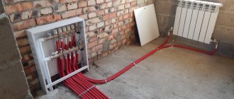
The manifold for a warm water floor is mounted according to the following scheme:
- It is necessary to install a frame under the device. It is mounted directly on the wall in a horizontal position or in a specially prepared niche. When choosing a location for installation, you should be guided by the availability of free access to the device to connect the required number of pipelines. Also, a special cabinet is often used to mount the device. In this form, the device can fit into any room.
Diagram of a collector unit in a heated floor system - Connection to the heating boiler. The coolant is supplied to the system from below, and the return is placed at the top. You also need to install cut-off balls in front of the frame. A circulation pump is installed behind the taps.
- The bypass valve is being installed. It must be equipped with a temperature limiter. Behind this unit the distribution comb is installed.
- Pipelines are being laid to the heated floor. The elements through which coolant will flow into the system are placed on top. Pipelines from underfloor heating are installed from below.
Connection diagram of the heated floor collector to the boiler - If you intend to install the device yourself, you must connect shut-off valves that are equipped with a thermostat to the distribution comb. When installing a ready-made kit, this is not necessary.
- The collector is connected to the heating system using compression fittings. This element consists of a clamping ring, a support sleeve and an intermediate nut.
- Pressure testing of the collector. After installing all structural elements, it is necessary to check how tight the resulting system is. To do this, the unit is connected to a circulation pump. With its help, pressure is built up in the system. The water circuit is left in this form for a day. After this time, the pressure is checked. If it has not changed, then the installation was successful.
What needs to be done before installation?
Proper installation of a warm water floor requires careful preparatory work. During their course, all the little things must be taken into account, on which the effective functioning of the structure will subsequently depend:
It is best to entrust the design of the future system to specialists, since it is quite difficult to make independent calculations.
It will be necessary to determine the length of the pipe, the pitch of its installation and the power of the heating circuit, if there are several of them, then for each separately. In this case, many nuances and parameters are taken into account. There are special calculation programs that many people use.
However, you need to understand that a flaw in the calculations will lead to a decrease in efficiency or simply the impossibility of functioning of the entire system. Equipment for heated floors must be of high quality, manufactured and purchased from a reliable company that offers good guarantees.
It will be cheaper to pay for a quality product than to subsequently constantly shell out decent sums for expensive and labor-intensive repairs. To minimize the thermal load on the screed and prevent it from cracking, the system should be divided into sections of no more than 40 square meters. m. The base for heated floors must be carefully prepared.
It must be clean and level, differences of more than 5 mm are not allowed. To prevent heat loss, a heat-insulating layer must be spread on the prepared base, with a height of 3 to 15 cm, depending on the operating temperature of the coolant. This could be special heat-insulating materials or mats designed for warm water floors. The latter can be equipped with pipe mounts, so-called bosses, which is very convenient.
A damper tape is laid around the perimeter of the room and between the installation areas, which can compensate for temperature fluctuations of the screed.
Mats with bosses designed for water heated floors are very comfortable. They not only act as a heat insulator, but also secure the pipes in place
When drawing up a laying scheme, you need to avoid a large number of pipe joints, which carry the potential danger of leaks under the floor. It is best to arrange the safest option, where connections are present only at the outlet and inlet of the collector. In this case, the length of the solid pipe should not be more than 90 m, otherwise the temperature of the circulating coolant may drop.