How to save time on laying a stove?
What takes the most time when laying a stove? You might say - the masonry process itself... But no, that would be a mistake... What consumes the most time is finding the right tool/consumables. Especially if the laying process has already begun, and something is “suddenly” missing.
Ignorance or uncertainty about one thing or another also takes up a lot of time: masonry method, project, building materials, consumables. All these searches and thoughts... And sometimes when laying masonry, some 4 mm concrete drill is missing and you have to spend hours traveling... for a drill that costs 50 rubles.
It’s not always possible to find on the Internet in one place all the comprehensive information on laying a furnace: where you’ll find a furnace design, somewhere an order, maybe a good video on materials, somewhere on a solution... But to put it all together, you give up. Well, if they don’t go down, weeks, or even months and years pass before we gain confidence that we will build an excellent stove.
What really saves time, as always, is a clear plan and structure. This is often available only to professionals, and even then not to everyone. I suggest you download a free mind map - what the process of creating a furnace consists of and how to achieve the desired result - A FURNACE PUT INTO OPERATION (the link to the mind map will open in a separate tab).
You may have already thought through most of these steps and have a solution. Well, if not, then each stage is divided into further steps - large and small - that need to be completed. You will go through these steps in any case, you just may not even notice it. It happens often. For example, you make a decision thinking that you have no choice (for lack of information). Therefore, it may seem that this is “not a question” at all, but simply a given. But for professionals, any nuance turns into a “question” that needs to be resolved...
Therefore, preparation for the masonry process itself is an important stage that saves time.
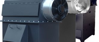
Do-it-yourself Kuznetsov stoves ordering
Igor Viktorovich Kuznetsov is a well-known Russian engineer-inventor who has been developing new models of furnaces and their constant improvement since 1962. During this considerable time, more than 150 different models have appeared, thoroughly tested in practice and have earned the widest demand among the owners of private houses. The designs of this inventor are distinguished not only by their effective work in heating residential buildings, but also by the ability to add comfort and originality to the interior of the premises.
Do-it-yourself Kuznetsov stoves ordering
It is not so easy to build Kuznetsov stoves with your own hands, the order of which, I must say, is quite complicated. However, if you want to save a decent amount, and also if you have certain skills and the ability to read the relevant diagrams, this is quite possible. Therefore, if you decide to carry out this work yourself, you need not only to choose a suitable structure, but also to very carefully study its order and recommendations for laying.
Design features of I.V. Kuznetsova
Judging by the design features of the heating devices, the engineer, when carrying out his developments, set himself two goals - the efficiency and productivity of the stoves. That is why the inventor pays great attention to the arrangement of the internal channels of the furnace, through which there is intense movement of combustion products along with the air heated in the furnace. Working on designs, the master in each of his models tries to achieve a longer retention of the heated gas mass inside the furnace structure, which helps save fuel while maintaining heat for a long time.
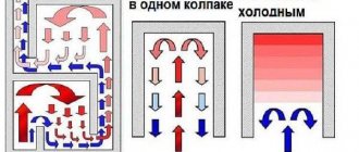
These characteristics correspond to stoves called “bell-shaped”, that is, they have special chambers for retaining heat. Typically, Kuznetsov’s designs have two “hoods” - the lower one, combined with the combustion chamber, and the one located in the upper part of the furnace. The operating principle of the lower “hood” is to separate the generated gases into hot and cold. Thus, combustion products, rising to the ceiling of the hood, are retained and accumulate heat, while in many structures the heated air does not encounter any special obstacles to exit into the chimney.
The principle of operation of two “hoods”
Gases are also retained in the upper “cap” because the exit from it is located at its base. Thus, before entering the chimney, hot gas flows rise to the ceiling, heating the entire chamber.
Thanks to this system, the internal temperature of the furnace increases significantly and is maintained for a long time, which gives a high efficiency of the heating device, reaching up to 95%. The difference can be seen if we compare this parameter, for example, with the efficiency of a Russian traditional stove, which, alas, is only 45÷50%.
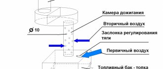
In addition to rational air movement, the conservation of thermal energy is also facilitated by valves installed in the right places, which can also delay or redirect the movement of gases as necessary. These elements are also able to regulate heat circulation. So, when the “summer” valve is opened, the stove will be set only to cooking, because the heated air will go into the chimney along the path of least resistance, heating only the firebox and hob, without getting into the upper bell part of the structure.
Such a stove can operate in two modes: “summer” and “winter”
Thanks to such a working furnace system, one can highlight a number of advantages of the designs developed by I.V. Kuznetsov:
- The oven warms up and releases heat naturally and evenly.
- It becomes possible to allocate more space for installing a heating element - a hob.
- Combustion occurs without the formation of soot and smoke, since combustion products are almost completely destroyed.
- Heat losses are reduced to a minimum.
- Due to the uniform heating of the structure, there is almost no deformation of the masonry and the formation of cracks in the seams.
- This internal design allows you to create various shapes of stoves and with a variety of designs.
- In addition, furnaces developed by I.V. Kuznetsov, can be equipped with a water circuit or a built-in heating tank, which will provide hot water supply in the house or even water heating of other rooms.
You can equip the Kuznetsov stove with a water circuit for a local heating system
When using the operating principle of such a stove design, it becomes possible to create various household stoves, depending on their purpose:
- A heating type of stove designed only for efficient heating of a residential one-story or two-story building.
- Cooking ovens designed primarily for high-quality and quick cooking.
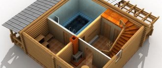
- Sauna stove options - for efficient heating of sauna rooms.
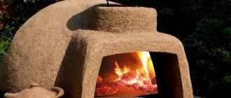
- Outdoor oven-barbecue complexes, with grills and smokehouses.
- Fireplace stoves, which are intended not only for basic heating, but also for creating a cozy environment and an aesthetically attractive interior in the house.
- If desired, you can create multifunctional versions of stoves, including heating, cooking and aesthetic functions.
How to fold an I.V. oven Kuznetsova
The construction of a real brick oven is always a rather labor-intensive and complex process that requires certain knowledge, technological skills, and possession of certain secrets of craftsmanship. Therefore, in order to get a high-quality heating device, you need to gain some experience in this work in advance. Masters who have been practicing this art, without exaggeration, for a long time, advise novice stove makers to carry out preliminary masonry work before major masonry - without mortar, that is, dry.
The construction of any brick kiln is a rather complex and labor-intensive process.
In addition, if you are laying out your first oven, you should not experiment, trying to add your own innovations to the already established order. In this case, it is recommended to strictly adhere to the chosen scheme and carry it out without any deviations. Therefore, you should immediately decide on the functions that the stove should perform. Since, I.V. Kuznetsov developed and compiled more than 150 designs, from which you can always choose the appropriate option.
If the construction of a stove is planned at the stage of building a house, then its installation should be designed in such a way that it heats two or even three rooms at once.
It is more difficult to build stoves into an already built house, since you will have to make precise calculations to remove part of the wall. In this case, wall-mounted options are usually chosen, but they are capable of efficiently heating only one room. However, if desired, it is possible to solve any problem, of course, taking into account the location of the floor beams and load-bearing walls.
If desired, a brick stove can be built into an interior wall
It is important to protect flammable surfaces from overheating, therefore, if the stove is installed in a wooden building, then at the junctions of the walls of the house and the stove it is necessary to make gaskets from non-combustible material, for example, asbestos.
In addition, at the joints of structures, gaps filled with such material are also necessary for the free expansion of the brickwork when it is heated, otherwise the mortar in the seams may become covered with cracks, and the structure of the furnace itself may undergo deformation.
It is very important to arrange a high-quality foundation for the furnace structure. It is usually made of concrete with waterproofing. The foundation of the furnace should not be connected to the foundation of the main building, since they will shrink differently and should not “pull” each other along with them.
The linear dimensions of the concrete foundation must be larger than the dimensions of the furnace base by at least 100 mm on each side of the structure. The depth of the foundation is calculated depending on the massiveness of the furnace structure and the composition of the soil on which the construction is carried out. On average, the depth of the excavation pit for the foundation varies from 400 to 600 mm, and a waterproofing sand cushion and a reinforcing layer of crushed stone are necessarily laid at the bottom. Well, the side walls are formed by installing wooden formwork.
The process of arranging the foundation is quite labor-intensive, however, it must be carried out in full and with high quality, since the accuracy and durability of the entire furnace structure will depend on its reliability and smooth surface. You should never rush into construction - the poured concrete foundation must be given at least a month to fully mature and harden.
Moving on to further work, when laying the stove you need to take into account the following points:
- Before laying the first row, one or two layers of waterproofing material - roofing material - are laid on the foundation, which is further recommended to be marked with chalk according to the size of the stove base. This will make it easier to lay the first row.
A brick stove will definitely require a reliable foundation
- If the furnace masonry work is planned to be made of red brick, then it is recommended to line the combustion chamber with fire-resistant fireclay material. It retains heat longer and is resistant to high temperatures.
- It is very important to maintain thermal gaps of 5 mm between fireclay and red bricks - their coefficient of linear expansion differs significantly, and the material must be allowed to expand freely when heated.
- It is recommended, after raising each successive two rows, to reinforce the furnace wall with wire, which is laid in a seam along the entire length of the row.
- Cast iron and steel elements that will come into contact with open fire are wrapped around the perimeter with asbestos rope or fragments cut from a single sheet. This material will not only protect the metal from burning, but will also create the necessary gap for thermal expansion.
- The folded oven must be dried for a long time before use. To do this, all doors and valves are opened for free air circulation throughout all departments of the structure. Drying is often done by installing a regular incandescent light bulb with a power of 200÷400 W in the firebox. The heat given off by the light bulb and the through air movement created from this will contribute to faster drying of the structure.
- The dry stove is first heated with a small amount of fuel, the flame from which will harden the walls of the combustion chamber with fire.
- If you plan to carry out external finishing of the building, then it should be done after at least one season of operation of the heating device, when the folded stove will shrink almost completely.
You may be interested in information about what a fireplace stove with a water heating circuit is
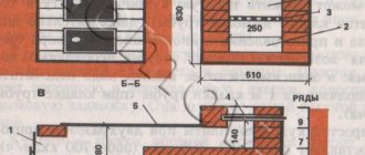
Order diagram and materials for construction
The order is the scheme that is developed for each furnace. This graphical plan shows in detail the configuration and quantity of materials for each row. Before starting work, you need to carefully understand the order scheme, and if it is not clear, then you should seek clarification from a specialist. As a rule, it is quite easy for a technically savvy person to understand the order drawings, especially since they are usually accompanied by a detailed description.
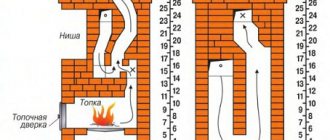
This is what the flowchart usually looks like
The sequence diagram should look something like this. The best option is if the arrangement diagram contains several more options for sections of the furnace - this will help to see the internal structure of the structure and will greatly facilitate the work.
In different sections of the furnaces, both whole bricks and hewn or chipped bricks can be used into several equal parts. In some cases, the brick can even be divided into 8 parts, and ⅛, ⅜, ¼ bricks, etc. are used to form some sections of the kiln. The use of these parts is always indicated on the order diagram.
In addition, you need to know that some bricks will need to be cut out to install metal elements, such as a hob or valve. In some cases, you will have to trim or cut the brick at a certain angle, which is also shown in the order.
Each specific model requires a certain amount of material, which can be calculated independently based on the order, or the list is attached to it in ready-made form.
To build any furnace you will need to purchase the following materials:
- For the internal masonry of the firebox, it is recommended to prepare fireclay bricks (ША-8). If it is not available, then you can replace it with another refractory brick.
- For the main masonry of the building, you will need ordinary ceramic bricks with a strength grade of at least M150.
- The solution will require one or two types of clay, one of which must be refractory and ductile. This material will require 100÷150 kilograms, depending on the massiveness of the structure.
- In addition to clay, the solution will require sifted sand. Its volume should exceed the amount of clay by 2÷2.5 times. In total, for a masonry consisting of 500 bricks, it is necessary to prepare 0.2 cubic meters. m. clay-sand mixture. However, many modern stove makers have already managed to evaluate ready-made masonry mixtures for stoves, which can be purchased at a specialized store.
- Metal and cast iron structural elements are selected individually for each model. The amount of wire for reinforcing the rows will also depend on the choice of oven model and its perimeter.
Prices for ceramic bricks of strength grade M150
ceramic brick m150
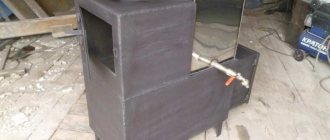
Detailed order of the Kuznetsov heating and cooking furnace OVIK-9
The heating and cooking furnace presented below is designed based on the OVIK-9 model, developed by engineer V.I. Kuznetsov. The only difference between these structures is the relative position of the combustion and blower doors, but otherwise the structures are completely identical.
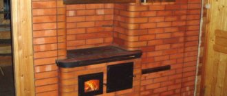
Heating and cooking furnace based on the development of I.V. Kuznetsova OVIK-9
This version of the stove is designed both for heating the house and for cooking, so it is quite suitable for installation in any country private houses.
For cooking, the model has a cooking chamber with a two-burner stove and lockable metal doors. It is equipped with its own exhaust duct with a valve, with which you can regulate the temperature inside the closed niche. Due to the fact that the chamber can be completely closed, it can serve as an oven, so brackets for installing baking sheets are often built into its walls.
If it is necessary to quickly heat the premises, the cabinet doors are left open, but even in this case, food can be cooked on the hob itself.
The stove has a two-bell design, so it can operate in two modes - “summer” and “winter”, that is, it can be lit only for cooking in the summer or heating the house and cooking in the winter.
The depth of the fuel chamber is 450÷470 mm and has a “dry” seam for free expansion of the material when heated. If desired, the dimensions of the combustion chamber can be increased to 510÷530 mm - for this, the rear wall of the firebox will need to be laid out not in half a brick, as indicated in the order, but in a quarter of a brick. However, in this case, it is not recommended to use a “dry” joint, since the wall will be unstable and the bricks in it may be displaced when laying firewood.
Such a stove has dimensions of 1015×630×2100 mm, has a heat output of 3600 W, provided it is fired twice. It is quite capable of heating a room or adjacent rooms with an area of 30÷35 m².
Necessary materials
For the construction of this heating structure, the following materials will be required (excluding the construction of the pipe and the arrangement of the foundation):
- red brick – 430 pcs.;
- fireclay refractory brick (ША-8) for the firebox – 22 pcs.;
- combustion door (DT-3) 210×250 mm – 1 pc.;
- blower door (DPK) 140×250 mm – 1 pc.;
- grate 250×252 mm – 1 pc.;
- two-burner cast iron hob 586×336 mm – 1 pc.;
- cooking chamber doors 510×340 mm – 2 pcs.;
- valve for the cooking chamber 130×130 mm – 1 pc.;
- valve for “summer” operating mode 130×130 mm – 1 pc.;
- chimney damper 130×250 mm – 1 pc.;
- steel corner 36×36×4×600 mm – 4 pcs.;
- steel strip 40×4×600 mm – 1 pc.;
- steel sheet 600×550×3 mm – 1 pc.;
- steel pre-furnace sheet 500×700×3 mm – 1 pc. It can be replaced with another heat-resistant material, such as ceramic tiles.
Prices for fireclay refractory bricks (ША-8)
Fireclay refractory brick sha-8
Furnace construction process
| Illustration with the order of the furnace masonry | Brief description of masonry operations |
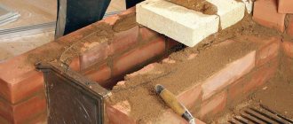
| The first row is completely solid, since it is the basis for the rest of the order, so it must be laid out with precise observance of the horizontal masonry and with perfectly aligned right angles. The diagram shows standard dimensions, and they can be slightly changed, since the parameters of the brick and the thickness of the seams between them may vary slightly. As a rule, the thickness of the seams is usually taken to be 5 mm, but it should be taken into account that the corners of the remaining rows of masonry should ideally coincide with the base. Therefore, they need to be measured using a construction angle, and then compare the dimensions of the diagonals of the resulting rectangle - they must be equal to each other. This row will require 20 red bricks. | |
| On the second row, the formation of the ash chamber and the lower furnace hood begins. Since the base of the cap will need to be cleaned after completion of the masonry, two halves of bricks are installed, which protrude outward from the common row. During cleaning, these elements are removed from the wall, which allows this process to be carried out without problems. When laying the second row, these bricks are not fixed to the mortar - this will be done after the stove is completely erected and cleared of fallen mortar and other construction debris. A blower door is installed on the same row, which can be temporarily supported with stacks of bricks for stability. This row uses 14 red bricks. | |
| The third row is laid out according to the diagram. In the process of laying it, the blower door is tightly fixed to it. | |
| The fourth row is partially laid out from fireclay refractory bricks - the side and rear walls of the fuel chamber are formed from it. The door of the ash chamber is covered with two red bricks, which extend above it and are cut at an angle. In the same way, two hewn refractory bricks are placed on the back side of the blower door. A thermal gap of 5 mm is left between the red and fireclay bricks. To fulfill this condition, the craftsmen use a little trick, and instead of mortar, they place ordinary packaging corrugated cardboard, which has the required thickness, between these types of bricks. After it burns out, a perfectly even thermal gap remains. Such gaps should also be provided in subsequent rows where red and fireclay bricks are joined. For this row you need to prepare 11½ red and 3½ fireclay bricks. | |
| The fourth row continues. After laying the side bricks above the blower door, the middle of the door is covered with fireclay and ceramic bricks, hewn on the sides on both sides; this masonry system is called a “castle”. To do this you will need 1 red and 1 fireclay brick. | |
| On the fifth row, a fuel chamber is formed. The fireclay brick installed on the front wall of the firebox is cut obliquely. The space inside the firebox between the fireclay bricks must correspond to the size of the grate, since it must fit freely into the rectangle formed by the bricks, on the bricks of the lower 4th row protruding by 10÷15 mm. At the same time, it is necessary to leave a thermal gap of 5 mm between the side walls of refractory bricks and the grate, which will allow the metal to expand without problems when heated. In the space behind the firebox, where the lower hood of the furnace is located, a separate vertical channel is formed, the size of half a brick. This channel will connect the lower and upper furnace hoods. The number of bricks used in this row is 12 ½ red and 4 fireclay. | |
| On the fifth row, without mortar, a grate is laid on the protruding bricks of the 4th row. The five-millimeter gaps between the brick and the grating are filled with sand. | |
| Sixth row. At this stage the fuel door is installed. There should be a gap of 5 mm between the walls of its frame and the adjacent bricks, which is filled with non-combustible material. To do this, most often the frame is wrapped with rope or pieces of asbestos. To lay this row, you need to prepare 12 red and 3 fireclay bricks. | |
| Seventh row. When laying the back wall of the fuel chamber in this row, a gap of 20÷30 mm is left on the left edge of the brick - this will be the “dry” seam. It is necessary to remove unburnt gases from the furnace and create conditions for more intense combustion of the flame. This row will require 12 red and 3 fireclay bricks. | |
| Eighth row. The masonry is carried out strictly according to the scheme using 12 red and 3 fireclay bricks. | |
| Ninth row. The walls of the combustion chamber are removed, and a passage is formed between it and the lower hood to remove combustion products. The fireclay side walls of the firebox should be 10 mm lower than the rest of the row (these walls are highlighted in lilac in the diagram). The fireclay and red bricks placed above the fire door are moved slightly to cover part of its frame. These bricks are first cut diagonally and thus form a kind of “bowl” into which the central brick will be laid. For a row, 12 red and 2½ fireclay bricks are used. | |
| On the ninth row, between the front side bricks above the door, a central brick covering the frame of the combustion door is placed, previously hewn obliquely on both sides at the same angle as the side ones, forming a “bowl”. The left side wall of the fireclay brick firebox is covered with an asbestos strip 10 mm thick, which will equalize this side with the height of the entire row. | |
| Tenth row. In this row, red brick is laid dry on fireclay bricks covered with asbestos, that is, without mortar. In the red brick framing the firebox, a small cutout approximately 10 mm in size is made, on which the hob will be laid. Moreover, between the slab and the walls of the brick on all sides there must be a gap of 5 mm for the expansion of the metal when it is heated. The refractory bricks installed on the front and right side of the fuel chamber are cut at an angle - they are shown in orange in the diagram. At the same time, it is necessary to ensure that there is a gap of 10 mm between the fireclay bricks and the hob. This row will require 14½ red and 1½ fireclay bricks. | |
| After completing the previous work on laying the 10th row, asbestos rope impregnated with clay mortar is distributed onto the cutouts in the laid bricks. The hob is laid on top of the asbestos layer. The gaps between the slab and bricks are filled with sand. If you purchased a panel that has stiffening ribs on the reverse side, then additional cutouts are made for them. The hob should lie only on its edges, but not on the stiffeners, and be “recessed” relative to the surface of the entire row by 5 mm. | |
| 11th row. From this row, the walls of the cooking chamber begin to form and a frame with doors is installed. Moreover, it must be taken into account that a five-millimeter gap must be maintained between the metal frame and the bricks. To make it easier to form, it is recommended to wrap the frame with asbestos rope. For the 11th row you will need 11 red bricks. | |
| The 12th row is laid out according to the pattern, and 11 red bricks are used for it. | |
| 13th row. The formation of the cooking chamber and vertical side channels continues. | |
| 14th row - work proceeds strictly according to this scheme. | |
| The 15th row is placed in two stages. The first step is to raise the walls of the cooking chamber and vertical channels to the level of the metal door frame. | |
| Next, it is necessary to arrange the overlap of the cooking chamber. To do this, a 600x550 mm steel sheet is laid on the 15th row masonry, in which a cutout is made for the exhaust duct. The metal sheet is necessary so that the ceiling of the cooking chamber is cleaner, and during cooking, various debris in the form of mortar from masonry joints does not fall on top of the food. For rigidity, four metal corners and a steel strip are installed on top of the sheet. | |
| 16th row. Red brick is laid on the metal corners and strip - the order is shown in the diagram. Only the openings of the vertical channels are left open. Before laying, on the bricks framing the nearest vertical and exhaust ducts, cutouts are made for installing chimney dampers. The valves will ensure the “summer” operation of the furnace and, if necessary, the tightness of the cooking chamber. The cutouts are made in such a way that there is a gap of 5 mm between the brickwork and the valve. In this row the masonry consists of 20 red bricks. | |
| On the 16th row, two valves are installed on prepared platforms with cutouts. | |
| On the 17th row, the cooking chamber and installed valves are covered with red brick, so that the smoke exhaust channels remain open. For masonry you need to prepare 19 red bricks. | |
| On the 18th row, the formation of the upper cap of the structure takes place. To do this, two half-bricks are installed dry, which rise above the main masonry - they are necessary to clean the base of the cap. These bricks are fixed to the mortar after the laying of the stove is completed and the base is cleared of mortar and debris. The row uses 13½ red bricks. | |
| The 19th row is laid according to the pattern using 12½ red bricks. | |
| The 20th row is also laid out according to the pattern and will require 13½ red bricks | |
| 21st row. The masonry is carried out according to the presented scheme, and 14 bricks are used for it. | |
| Next, a rather long section of the building is laid out according to a single pattern, only with alternating even and odd rows. 22nd, 24th and 26th rows. The work is carried out according to the same pattern, the rows consist of 14 bricks. | |
| The 23rd and 25th rows are also laid out according to the general pattern and also consist of 14 bricks. | |
| 27th row. In this case, 14 bricks are also used, but the configuration of their arrangement is somewhat different from the previous rows, since they prepare the basis for subsequent almost continuous rows. | |
| On the 28th row, cutouts are made in the bricks framing the chimney channel to install the main chimney valve. In the diagram, the cutout locations, to a depth of 10 mm, are highlighted in lilac. When making cuts, you need to periodically try on the valve itself, since it should be at a distance of 5 mm from the brick walls, that is, it should fit freely into the cut gap. | |
| On the same row, the valve itself is installed in the cutout on the solution. | |
| For the 29th row, 19 red bricks will be required, since the surface of the structure is almost completely covered. Only the chimney opening with the damper already installed remains open. | |
| The 30th row covers almost the entire surface for the second time. It also requires 19 bricks. | |
| 31st row - the base of the mounted pipe is laid with a cross-section of the chimney opening, the size of one brick. Consists of a row of 5 bricks. | |
| Next, the chimney itself is formed. For each of the rows, when laying it out, you will also need 5 red bricks. |
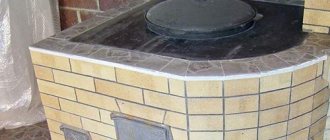
Detailed instructions and diagrams will help you lift this fairly compact stove model yourself. To make it look more elegant and neat, it is recommended to buy rounded shaped bricks for laying the corners or process them yourself. So, in addition to accuracy, the oven will also gain greater safety. This is especially important to provide for in cases where there are small children in the house.
If the order diagram is disassembled and understandable, then build a furnace designed by I.V. Kuznetsov will be quite simple. A correctly selected model is quite capable of decorating an interior made in any style. To make it neat and aesthetic, you shouldn’t rush - it’s better to do all the work measuredly, calculating each step and strictly following the attached diagram. Read about automatic coal-fired boilers on our website.
And at the end of the publication - a video about the laying of another heating and cooking furnace designed by I.V. Kuznetsova:
Video: Kuznetsov heating and cooking stove OVIK-4
Laying a furnace is a simple matter of complex things...
Well, the most interesting point of the intelligence map is, of course, the process of MASONRY OF A OVEN... Although the process of laying a furnace is only part of what we call laying a furnace. After all, there are also a lot of preparation points there...
For convenience, I divide the entire furnace masonry into 8 stages and here they are:
- Preparation for laying the furnace;
- Beginning of laying the furnace;
- Furnace laying process:
- Laying the stove up to the 10th row,
- Laying the stove up to the 20th row,
- Covering the stove, laying up to the 30th row;
- Pipe laying/installation;
- Joining, finishing and commissioning.
Now I want to Give you the order of a two-bell brick oven. Or rather, a 3D brick-by-brick project in the skethup program. This oven is quite powerful and compact. The estimated power of such a furnace is about 3.8 kW. in terms of bricks, it has dimensions of 4 * 3.5 bricks, which is approximately 1000 * 880 mm. This stove can heat up to 80 sq.m. with a certain layout. The project was made in google sketchup. To view the project you will need to download the program itself; for this project it is better to take the installer with version 2016.
Here is a link to the project and program, go to our projects page and fill out the form to receive a free project below or on the right:
Let's return to the masonry process... Each of the above points consists of sub-points that also need to be known so that the process does not stall.
Do-it-yourself brick oven: drawings and photos, step-by-step instructions!
Before giving a photo of the oven, I promised to give step-by-step instructions. Let's try to briefly outline it.
What do we need to prepare for laying the stove? This is what preparation for masonry is made of:
- Preparation of materials.
This is not about just bringing it to a construction site. Namely, prepare bricks and other materials for work. We have a whole section of training videos dedicated to this, which are available to you for free on our video courses page: HERE (the link will open in a new tab).
- Preparing the oven solution.
We also have a lesson about this on the courses page at the link given above. This is what our lessons look like:
Further:
- Tool preparation.
- Preparation of consumables.
And this is only what concerns the oven itself. But we still need to make a foundation and prepare a place for work - for laying a stove.
Next comes the process of starting the laying. Yes, this is also preparation for laying, but not quite. What is involved in this process?
- Foundation waterproofing;
- Zero row device, if there is one in the oven;
- Aligning the horizontal geometry of the furnace is also done before the start of masonry, in order to provide for all dimensions;
- Aligning the vertical geometry of the stove is done already during the laying process on the second row, but still this is a separate “trick” that we talk about in the video tutorials - how to practically not use a level (vertical) when laying the stove and save a lot of time.
You can get complete step-by-step instructions for laying a stove on my blog. My colleague and I recorded a comprehensive video course on laying exactly the stove for which I sent you the project.
Here is an introductory video about this course, but go to the course page to learn more about it: PAGE ABOUT THE COURSE, and here is the COURSE PAGE - where you can start learning masonry for free.
Materials for constructing a fireplace stove with a bread chamber:
- 1 - Kiln brick - approximately 1100 pcs. If you use fireclay bricks, you will need approximately 150 units. (The quantity of bricks is given without taking into account the costs of the foundation and chimney).
- 2 - Knitting wire
- 3 - Cleaning doors - 3 pieces
- 4 — Blower firebox with air adjustment
- 5 - Fireplace door for firebox 500x500 mm
- 6 – Basalt cord – 2 sets
- 7 – Pipe valve into brick – 3 pieces
- 8 - Grate with a working area of one or two bricks
What could be better than tidying up your oven? Only PHOTO ORDER OF THE OVEN!
The main advantage of photo ordering is maximum clarity. Photo-ordering of the stove will give more information than regular ordering. The order drawn in the program does not contain the colossal amount of detail that a photograph can contain. In addition, the ordering can be done quite generally. It may also contain a bunch of conventions and errors. There may also be some kind of error in it (after all, the seams are not drawn there).
And the order is quite clear - the layers of brickwork that outline the furnace outline. But the internal fireclay core, which is placed “on the edge,” is not always immediately clear. Therefore, everyone who lays in order has to delve into the stove design in sufficient detail before starting laying. That is, it is not as simple as it seems.
So, the disadvantages of stove orders:
- There are few details relating to the actual masonry process;
- Gives a fairly generalized plan (with some exceptions);
- Therefore, it is rare that there are no deviations from the original order ;
- The order, due to its “digitization”, may contain conventions and errors. And it’s not a fact that you will find out about it in time.
- The order may contain errors accepted in the stove-making community, but you will also not know about it.
- What really unsettles us (at first) is the desynchronization of the outer contour of the furnace and the internal fireclay core.
What is the advantage of designing a stove over ordering?
If you have a stove project, then at least the issue of desynchronization of the rows of internal and external masonry is removed. After all, in a three-dimensional project this is not a problem.
You can also see not just a row of the stove, but also each brick separately or several rows in cross-section. You can “move aside” the bricks with which everything is clear to see what is not entirely clear. In this case, not one row will be involved, but several, at least ten...
But there are also disadvantages. To work on the project, you need to have a laptop or other computer right at the construction site. You can, of course, take screenshots and print them or upload them to your phone... But here we are faced with all the disadvantages of the usual procedures. Although after studying the project in 3D, it will be easier to understand and implement the order.