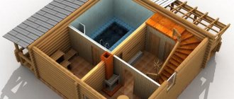
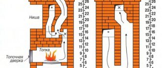
Foundation
A stove made of brick has a large specific gravity, so without a reliable foundation the structure cannot be installed.
The foundation for the furnace can be monolithic reinforced concrete, pile, columnar, lined with blocks, pile-screw.
Block foundation diagram
Columnar bases for furnaces
Regardless of the type, the foundation of the stove should not be connected to the foundation of the house. The type of foundation is chosen, as for a house, based on the type of soil.
The gravel-sandy soil allows for the development of a shallow foundation.
If the soil is clayey or sedimentary, it is better to pour the foundation on a crushed stone bed, while deepening it to the freezing level.
In permafrost zones, a pile-screw foundation is installed, paying special attention to the thermal insulation of the piles.
On dry rocky soils, the foundation may have minimal thickness or none at all.
Bulk soil is not suitable for installing a brick kiln.
Features of foundations depending on soil types
Let's consider a method for arranging solid bases for a brick kiln.
Step 1. Depending on the type of soil and the level of its freezing, we dig a pit. We take the width and shape based on the dimensions of the oven and adding 10-15 cm to its length and width, respectively.
Immediately pay attention to the location of the ceiling beams - the chimney pipe will have to pass between them, taking into account the deviations regulated by SNiP. It is also recommended to carry out drainage (drainage) from the furnace foundation to reduce humidity and soil heaving
Foundation pit
Step 2. We tamp the bottom of the pit and level it horizontally as much as possible. Pour a ten-centimeter layer of small broken brick, rubble stone or crushed stone. We repeat the tamping procedure.
Step 3. Prepare liquid cement mortar (ratio of cement and sand 1 to 3) and fill the embankment with it.
Scheme of a monolithic foundation for a brick oven
Step 4. Next you can go in three ways:
- combine ten-centimeter layers of crushed stone backfill with cement fill. This option is acceptable for foundations of small depth, namely up to 50 cm;
- install the reinforcement frame and fill it with concrete. The frame is knitted with reinforcement wire with a diameter of 10 mm. The cell size is 10x10 cm. Formwork is installed in the pit; the frame must be 5 cm from its walls and bottom, for which plastic clamps or pieces of brick are used. Concrete is poured inside, and the mixture is compacted during the pouring process with an internal vibrator or metal rod. The top pouring point should be 15 cm below the finished floor level;
- pour a reinforced concrete slab, on top of which lay the foundation walls of sand-lime or red brick, and fill the inside with backfilled concrete (loose aggregate should be less than or equal to the volume of concrete).
The first and third base options are completed with a layer of cement mortar. The filled layer is checked with a level and, if necessary, leveled with a rule or other suitable tool.
Further work is carried out after the solutions used in the process of pouring the foundation have completely dried.
Step 5. We lay the waterproofing in three layers, fixing it with mastic (for roofing felt we use tar, for roofing felt we use bitumen).
Step 6. Lay out a continuous row of bricks. We place whole bricks on the edges, halves on the inside. The brick base should be 5-7 cm wider than the existing foundation, but 5-7 cm wider than the stove itself.
Bricklaying
Brick stove foundation
We do not use cement to bind bricks together. On top of the masonry, which we also check for horizontalness, we put another layer of waterproofing, then lay out the second layer of brick, observing the dressing between the two rows. The brick base should ideally be exactly level with the finished floor or rise 3-4 cm above it.
We fill the space between the foundation of the stove and the house with river sand.
Electric resistance furnaces
Electric resistance furnaces are used for melting all low-melting solders and solders on aluminum and magnesium bases.
The resistivity depends on the temperature of the various heating conductors.
Electric resistance furnaces are a thermally insulated space with heating elements to convert electricity into heat.
The design of electric resistance furnaces is very diverse. Depending on the shape of the working space, they can be chamber, shaft, bell-type, conveyor, roller table, drum, carousel, broaching. Electric resistance furnaces with a power of up to 10–80 kW are usually single-phase, and with higher power - three-phase.
Depending on the shape of the working area, electric resistance furnaces are divided into tubular, crucible and muffle. They are made either with metal heating elements made from various heat-resistant alloys in the form of wire and tape, or with carborundum, carbon or graphite heating elements.
Electric resistance furnaces are used more often for heating non-ferrous metals and alloys, and less often for heating steel, since, for example, the temperature range for aluminum stamping is in the range of 400–475 °C.
Electric resistance furnaces are inspected daily by maintenance personnel. At the same time, pay attention to the condition of all parts of the electric furnace and the lubrication of the mechanisms, and at the same time clean it from dust and dirt.
Electric resistance furnaces are the most popular electric furnaces; The installed capacities of individual furnaces reach hundreds or even thousands of kilowatts, so the issues of rational operation of electric furnaces of this class are of great importance from the point of view of saving electricity and reducing production costs.
An electric crucible resistance furnace consists of a cylindrical metal casing with a bottom and a removable cap for removing gases. Inside the casing there is a lining made of normal and shaped fireclay bricks. The gap left between the lining and the casing is filled with heat-insulating materials.
Melting of the metal occurs in a cast iron crucible installed in the working space of the furnace. The upper tides of the crucible rest on a metal plate laid on the lining. The top of the crucible is closed with a lid through which a thermocouple is passed. Heating of the metal in a crucible to a temperature of 850–1000 °C is carried out using electric nichrome heaters placed on the protrusions of the fireclay lining. In the lower part of the furnace at the hearth level there is a hole for releasing liquid metal in case of burnout of the crucible.
An electric crucible resistance furnace is an expensive device, so it is advisable to increase its service life if possible. This is facilitated by careful care of electric furnaces and timely repairs.
An electric crucible resistance furnace for rolling metal is a ceramic tube with a heater made of a special alloy. The upper part of the heater pipe is covered with a special glass. The furnace temperature is controlled using a thermocouple. The furnace supply voltage is regulated by a transformer, which also serves as a counterweight in the furnace lifting mechanism.
Electric resistance furnaces, similar to flame ones, are divided into continuous and non-pass type furnaces. Heating of non-ferrous alloy blanks is carried out in furnaces with metal heaters operating at temperatures up to 900–950 °C. These furnaces are also used for heat treatment of forgings.
Electric resistance furnaces, especially crucible and reflective furnaces, are widely used for melting aluminum, magnesium and zinc alloys. However, these furnaces have low productivity and low thermal efficiency. The heating temperature in the furnace is in the range of 900–1100 °C.
Electric resistance furnaces and various types of electric heaters are connected to the power network either directly or through transformers. The latter make it possible to multistage or smooth control of the supplied power within certain limits.
A feature of some fairly powerful furnaces that is unfavorable for the power network is the regulation of their power by switching the heaters from a star to a series connection, which causes periodic asymmetry in the load of the network phases.
Chamber electric resistance furnaces with tape heaters used for heating metal are divided into two groups: direct heating furnaces and indirect heating furnaces. They are connected directly to the workshop electrical network or receive power from special transformers.
It is advisable to convert electric resistance furnaces with a temperature in the working space above 900–1000 °C to gas, since gas furnaces provide a rapid rise in temperature and a low cost of thermal energy. When switching to gas, the operation of the furnace is simplified, so its maintenance and repair can be carried out by less qualified workers.
Electric resistance chamber, stationary furnaces are used for melting aluminum alloys.
Electric resistance furnaces have special elements that, when current passes, heat up and create the appropriate temperature in the working space of the furnace for heating the workpieces. Resistance elements are located on the roof and along the walls of the furnace.
An electric resistance furnace as an object of regulation is usually characterized by high thermal inertia due to the large thermal capacity of heating elements, thermal insulation and other structural elements. Heated products often have significant thermal capacity. Therefore, the furnace temperature changes relatively slowly, and maintaining a constant temperature does not require a correspondence between the power entering the furnace and the power it consumes at each point in time. It is sufficient if this correspondence is satisfied for average power values over a long period of time. This greatly simplifies the temperature control system, allowing in many cases to abandon continuous control and use the simplest on-off control with an actuator in the form of a contactor.
Electric resistance furnaces are used to heat parts and workpieces and allow precise control of the temperature and uniformity of metal heating. They are intended for high-quality processing of steel (hardening, annealing, carburizing, nitriding), non-ferrous metals and various alloys. Electric resistance furnaces have a power factor almost equal to unity, and when usually installed in whole groups, they create a fairly uniform load on the busbars of the electrical substation.
It is recommended to paint electric resistance furnaces with aluminum paint once a year. This measure reduces the heat loss of the stove by 2–4% and gives it a neater appearance.
Chamber electric resistance furnaces with a retractable hearth are similar in design to flame furnaces, but instead of burners, heating elements are installed inside the working space through which electric current is passed.
Electric resistance furnaces are divided into direct and indirect heating furnaces. Electric direct heating furnaces are used in chemical production to provide certain chemical-thermal processes (graphitization of carbon electrodes, production of carborundum, carbon disulfide, glass melting) and in other industries: forging, upsetting, hardening of parts or products, used in heating frozen pipes, soil.
Electric conveyor resistance furnaces with a cooling chamber (two-chamber) OKB-765, OKB-720, OKB-715, OKB-700, OKB-615, OKB-557 and OKB-565 are methodical furnaces with continuous movement of processed products and are designed for heating steel (and other) products with subsequent cooling.
The OKB-565 conveyor electric furnace is designed to operate in an automatic line. Normal operation is ensured when they are installed in dry, enclosed areas, the air of which does not contain acid vapors or other corrosive substances.
Electric resistance furnaces have a number of advantages, including the simplest automation scheme for maintaining a set temperature within 3–5 °C, the absence of smoke exhaust systems, and ease of starting and stopping.
Direct heating electric resistance furnaces are widely used for melting sheet, container, section, and technical glass.
Direct heating graphite electric resistance furnaces are single-phase electric furnaces. The heated graphitized material is included in an electrical circuit through which an electric current flows, due to which the material is heated to a high temperature, reaching 2500–3000 °C. A mixture of carbonaceous materials and sand is poured onto the base of the furnace, which is a hearth, onto which the products to be graphitized are placed between the current-carrying electrodes. A mixture of carbonaceous materials and sand is poured into the lateral spaces between the products and the electrodes, forming a circuit for the passage of current between the current-carrying electrodes. The space between the side walls, top and loaded products is filled with heat-insulating mixture.
Electric resistance furnaces of this type require a voltage reduction to 2–10 V for direct heating or to 380/220 V for indirect heating. This ensures the ability to change the voltage over a wide range: 5–17 or 30–200 V.
The lining of electric resistance furnaces is made of such a thickness that ensures minimal energy consumption to compensate for heat losses and at the same time does not increase its cost and heat losses due to accumulation during heating.
The lining usually consists of two parts: fire-resistant masonry and thermal insulation. Refractory masonry, made from normal bricks, shaped refractory and special ceramics, forms a furnace chamber of a given shape and size, in which the heated load with auxiliary supporting and transport devices, as well as heating elements are placed.
For a single-zone electric resistance furnace of the charge type, during the period of heating the products, the average power consumption varies within the range from the rated power to the power used to cover heat losses.
For electric resistance furnaces of direct heating of continuous operation with melting of the charge, it is recommended that when automating them, it is recommended to abandon process regulation by changing the furnace power and use a change in the productivity of the furnace feeder with raw materials as a control action. In this case, maximum use of the installed capacity of the equipment is achieved. When processing a solid charge, the unloading speed of the processed material must be used as a control action.
Batch electric resistance furnaces include chamber, shaft and pusher furnaces. Electric resistance furnaces of indirect action have become widespread. In them, heat is released when electric current passes through special heating elements; the released heat is transferred to the material by radiation, thermal conductivity and convection (Fig. 1).
Rice. 1. Electric resistance furnace of indirect action: 1 – heated apparatus; 2 – furnace lining; 3 – thermal insulation; 4 – spiral heating elements; 5 – output busbars
In such furnaces, heating is carried out to temperatures of 1000–1100 °C. The lining of furnace 2 is made of refractory brick. Spiral heating elements 4 are placed in the grooves of the lining, to which current is supplied through electrical busbars 5. The heat released when electric current passes through the spiral heating elements is transferred to the heated apparatus 1 by radiation and convection. Thermal insulation 3 reduces heat loss to the environment.
The heating elements of furnaces are made of wire or nichrome strip (an alloy containing 20% Cr, 30–80% Ni and 0.5–50% Fe) or chromium-iron-aluminum alloys. The wire diameter is usually 3–7 mm; in the tapes used, the thickness to width ratio is 0.05–0.2.
The electrical circuit diagram of a resistance furnace is shown in Figure 2.
Rice. 2. Schematic electrical diagram for controlling a resistance furnace: AT – three-phase autotransformer to power the circuit heater; IM with EMT – asynchronous motor with an electromagnetic thermometer for raising and lowering the chamber door; KP, KO – contactors for raising and lowering the chamber door; VKP, VKO – limit switches for the raised and lowered state of the door; CL – linear contactor; RP – intermediate relay for switching cable lines; DT – furnace temperature sensor; UP – mode switch; PTK – control device; Kn.P, Kn.O, Kn.S – buttons “Raise”, “Lower”, “Stop” of the door. Operating modes: automatic (main from PTK) and manual (backup from UP)
Installation of oven doors. Adviсe
Before installing the door, it should be checked for good fit and free rotation on the hinges.
We install doors
- If there are distortions or lack of smooth rotation, such defects should be eliminated, and if this is not possible, then replaced with new ones. You should also determine whether there are holes for mounting.
- For fastening, a soft (knitting) wire with a diameter of 2.5-3 mm and a length of about 50 cm is used. The wire is inserted into the hole and twisted.
- It is impossible to install the door after the masonry has been completed, so it is installed during the masonry process. In order for the door to hold well, the wire must sit in the seams, between the rows of bricks. Since the masonry is laid from bottom to top, the door is fastened in the same order. First, the lower ends of the wire are walled up, and then the upper ones.
- After laying the lower fastening ends, the door must be aligned strictly vertically and horizontally, followed by fixation. After the door is exposed, you can continue further work.
- This installation technique can be used to fasten combustion chamber doors, blower doors and other metal objects, such as valves, soot guards, etc.
- A very important step is installing the slab. It is installed on a clay mortar. The consistency of the mortar should be such that excess mortar comes out freely from under the slab, as a result of the pressure of its own weight. Its quantity should be such that it fills all the free space. We must not allow it to be small. Subsequently, under the influence of high temperature, the clay will sinter and reliably hold the slab on the surface.
Installing the slab
- After finishing the work, you need to allow the stove to dry completely. This is no less than 14 days, after which the stove can be heated.
- To make the stove attractive, it can be covered with tiles. This is where the quality of the masonry can come in handy, especially if it was done with your own hands. It will be easy to lay tiles on a very flat surface, especially since high demands are also placed on its installation due to the presence of high temperatures.
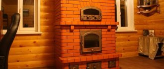
Brick heating stoves: we select drawings depending on the chosen design. Laying the working part is best done using clay mortar. You have the instructions and, having selected the desired model from the photo, you can start working.
Tools for laying a furnace
Regardless of the model chosen, to build a stove with your own hands you will need the following tools:
- trowel or trowel. They are used to apply mortar to bricks, and also use them to clean the masonry from excess mixture protruding between the seams;
- hammer-pick. It is used for trimming and splitting bricks, because in the process of laying bricks it may be necessary to adjust individual elements;
- jointing This tool is used only when the stove will not be decorated with decorative tiles and therefore it must look impeccable;
- building level. Can be used at any stage of construction. It is used to check the evenness of the brick row;
- plumb line Used to measure the verticality of a wall;
- order. An extremely useful device. With its help, the verticality of the masonry is maintained, maintaining an equal thickness of horizontal seams;
- rule. Apply it once to level the surface of the foundation;
- a spatula with which to stir the solution;
- solution container;
- measuring strip for measuring the width of seams.
https://youtube.com/watch?v=a9fxeuKNURg
Methods and order of masonry
Making masonry
Furnace laying can be done in various ways. This can be masonry with empty seams or undercut masonry.
Attention: These methods differ radically. When laying under trim, the seams are completely filled, and such a stove is not plastered
The thickness of the furnace walls can be brick or half-brick.
For laying stoves, only red solid bricks should be used. In this case, you cannot use used bricks, slotted bricks or other building materials not intended for this purpose.
The masonry technology consists of several stages:
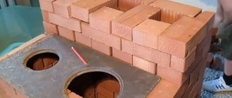
We cover the foundation with a layer of waterproofing. It could be a simple roofing material. We make the basement part. Its height is determined individually. Just don't make it too high. It is made with continuous masonry without voids.
Lay out the stove base
- The first row can be laid with bricks, without using mortar. After this, the bricks are leveled and the location of the front wall and the location of all the doors are determined. After this, masonry continues, but using mortar. As a rule, a solution of ordinary clay is used for laying stoves.
- Then you can install vertical beacons using plumbs and ropes or fishing line.
- Elements of the furnace, such as a blower, an ash pan or a combustion chamber, are located depending on the design of the furnace. As a rule, the ash pit is located after the third row of masonry, and one row after it is the ash pit.
- Then the firebox is laid out. The firebox door and blower are secured using soft wire.
- Next in line is the stove vault, which is formed after the second row of bricks laid above the firebox.
We make the combustion chamber only from refractory bricks
The combustion chamber is lined with refractory bricks. To increase the efficiency of the furnace, it must be equipped with various valves that regulate the flow of heated gases.
Technological order of masonry
The order of laying out the oven is as follows:
- The first row is laid out without mortar and leveled using a building level.
- Bricks are laid out at the corners using mortar and strictly horizontally. After this, the space is filled with bricks using mortar. This will be the first row.
- After laying out the first row, check the evenness of the sides of the oven using a tape measure. If there is a discrepancy, then they are corrected with the help of a mallet, knocking out one or another corner brick.
- After this, you can begin laying out the second row. The laying begins from the corners and continues along the entire perimeter. After the perimeter is laid, the middle of the second row is laid.
- Then, at the corners, between the first and second rows, nails 80 mm long are driven in and using a plumb line, the corner is projected onto the ceiling.
A nail is driven in at the corner projection site and a rope is pulled from below to the ceiling. This operation is performed with all angles.
- The stretched cords will serve as a guide for further work. Subsequent rows, relative to the vertical, will be controlled by stretched cords that define the contour of the future furnace.
- All subsequent rows are laid out in the same way, controlling horizontality using a building level. During laying, you need to make sure that there is no excess mortar, and the walls of the chimney should be wiped with a wet rag every 4-5 rows. In this case, you need to ensure that the solution in these places completely fills the seams.
- The brickwork seams for the stove are made as thin as possible, and the seams are filled 100%. Masonry with thick seams is less durable, as they may partially fall out.
- The laying of the stove is carried out with the bricks tied, otherwise it will not hold. The meaning of the dressing is to ensure that the vertical seam of the next row is located somewhere in the middle of the brick of the previous row. This does not always work out and the vertical seam “walks” from the center of the brick, now to the left, now to the right. This should be constantly monitored and the masonry adjusted so that the center of the vertical row does not extend beyond ¼ of the brick.
- The cut brick is laid outside the chimney duct, since the cut surface is considered weaker and can collapse under the influence of temperature.
Using fireclay bricks
Fireclay brick has excellent resistance to high temperatures and is therefore used to form the combustion chamber.
- Due to different coefficients of thermal expansion, the bricks of the combustion chamber are not tied to the bricks of the stove. There should be a gap of about 5 mm between them.
- When laying out a firebox from fireclay bricks, you can lay out the entire row or, after laying out, line the firebox with fireclay bricks.
Wood stove efficiency
(calculation based on a real example)
Now let's talk about the economic efficiency of the combustion method described above. I am deliberately switching to first-person communication because I will give examples, measurements and calculations made by me personally in real life.
As a “testing ground” I chose my bathhouse, which at the time of construction of the house was also a temporary shelter, equipped for permanent residence with all the necessary amenities, and made a simple but clear calculation.
Initial data
Building area 30.25 sq.m. On the attic floor there are two rooms of 12.00 sq.m. Total, total
living area is just over 50.00 sq.m.
The walls are made of timber 100 mm thick. The building is insulated in accordance with the requirements of SNiP 23-02-2003 “Thermal protection of buildings”.
For heating, a sauna stove with a direct periodic fire is used (the stone bed is heated during the fire by flue gases, and the steam room can be used only after the fire is finished) made of clay building bricks. The firebox is lined with refractory bricks. The wall thickness of the firebox is 250 mm (1 brick), the wall thickness of the remaining parts of the stove and chimney is 120 mm (1/2 brick).
The first floor is heated by a stove, the attic floor is heated by a heated chimney.
Calculation of the amount of heat required for heating
According to generally accepted standards, heating such a room during the cold period requires a source (boiler) with a capacity of 5.0 kW/h, operating constantly. Taking into account the coefficient of 0.7-0.8 for an insulated building, sufficient boiler power is 3.5-4.0 kW/h. The total amount of heat required per day to heat my bathhouse is 84.0-96.0 kW.
Real consumption when firing a furnace
For the experiment, I chose one of the periods in winter, when I lived in a building for a week at an outside temperature of about -20°C. Starting from the second day, when the room warmed up, the consumption of firewood per day amounted to two full bags (about 20 kg in total) or four such armfuls.
The combustion was carried out once in the first half of the day. The temperature inside the room was always 20-22°C. Knowing the calorific value of firewood – 4.2 kW/(h*kg), it is easy to calculate how much heat had to be used to maintain a comfortable temperature. I did not take into account the burning time, since the combustion was carried out once a day for about 1 hour.
So, for heating I spent 4.2 kW/(h*kg) x 1 hour x 20 kg = 84.0 kW, that is, the same amount as could be obtained with a 3.5 kW/h boiler.
Result
In a real comparison, it turned out that a wood-burning stove with a rational combustion method has almost the same efficiency (efficiency factor) that can be achieved using a conventional electric, gas or solid fuel boiler providing a heating system with a liquid coolant. And given the availability of firewood compared to other types of fuel, a wood-burning stove turns out to be more economical than other types of heating.
If you correctly calculate the power of a wood-burning stove, a rational firebox will allow you to significantly save on fuel. At the same time, the comfort of living in a house heated by a stove may be no worse than in buildings with a water heating system from a boiler.
Similar
Masonry of a Russian stove
Before work, it is important to study the designs of Russian stoves. There are different options, so the masonry scheme may differ
The drawings cannot be changed - the specified order must be strictly followed.
Complete tightness is important for the safety of the structure. This is ensured by the following points:
- Use quality stone. There shouldn't be any cracks.
- The seams between the rows are 0.5-0.8 cm thick.
- Do not coat the inner walls with clay - soot will be deposited on them, and therefore thermal conductivity will decrease.
- Different departments differ in the thickness of the masonry from ¼ of the thickness of the brick to its full length.
- If the brick is ceramic, then it needs to be soaked to prevent moisture from being absorbed from the mortar.
Diagram of the simplest brick stove for a summer house and home
A heating stone stove in general looks like this:
- Below the floor level there is a foundation on which the insulation is laid.
- Trenches are installed on the floor - legs that provide heating to the lower part.
- Directly above them there is a blower, as well as a choke. It is needed for uniform heating throughout the height.
- It is separated from the main room by a blower door.
- Directly above it is the firebox. A grate is placed at its bottom, which is also the roof of the ash pit.
- Directly above the firebox door is the arch of the firebox, behind which is the hailo or mouth.
- Above that, the cleaning, the pass and the convectors begin.
- There are two valves located above the cleaning.
- Almost at the very top there is an outlet for the air vent into the room, a smoke channel and a ceiling.
- The chimney is separated from the ceiling by an internal trim.
- At the very top is the mouth of the chimney.
Heating stove diagrams
Before choosing, you should familiarize yourself with the design options for each design.
Diagram of a heating furnace Construction of a cooking furnace Construction of a heating and cooking furnace
You immediately need to think about the installation system. After all, each design has its own requirements. Heavy ones will require a large foundation. For cooktops, you can get by with a small stovetop.
4a21b1eb90fc532b5417af3d3fc20fc3.jpe
Preparatory work
First you need to decide on the location of the future furnace. The first time a stove is erected is when housing is being built, which means that the shape and dimensions of the stove have already been determined, as well as its location.
Photo of the foundation diagram for the furnace
- The location of the stove largely depends on the layout of the entire building, and its location should be such that it effectively heats the entire living space.
- If the location is determined, you can begin building the foundation. Its dimensions should be slightly larger than the geometric dimensions of the furnace. During its construction it is necessary to install waterproofing.
- When carrying out masonry, you should remember that the seams should be minimal and the evenness should be maximum.
- When laying out the internal surfaces of chimneys, there should be no sagging of mortar, and the surfaces should be smooth. It is advisable to remove excess mortar released from the seams. Both the side surfaces and the corners must be laid out carefully.
Attention: The foundation must support the weight of the structure. Therefore, it will need to be reinforced. This will add additional rigidity.
Furnace classifications
| Kamenka | Flow-through | Deaf |
| Open | "Black" batch oven | Continuous oven |
| Closed | Batch oven | Continuous or combined oven |
Let us explain: if the heater is running, then the poured water will spill into the firebox. Therefore, you have to wait until the wood burns out, then just supply water. Since combustion stops, the operation of the stove is called “periodic” . Accordingly, the continuous stove is not filled with water and the wood can burn throughout the bathing procedures .
On a note! Most often, metal stoves are permanent, and brick stoves are periodic, but there are exceptions. If a solid heater is made in a brick stove, then such a stove is called a combined stove.
Inertness of the material
So, the fire burns, the stones heat up, and what happens to the steam room? If we need to heat the stones to 300-400 degrees, can you imagine how much the air in the steam room can heat up during this time? And now we come to the next important point: the role of material in the design of sauna stoves, in particular steam room units .
Stoves are either brick or metal . There is no other option. The former are considered very inertial - it takes hours to heat them up, as well as to cool them down . The latter are able to heat up in half an hour and during the same time manage to overheat the steam room. sauna stoves !
When choosing a design, you determine for yourself how inertial its body should be. At your disposal are not only “clean” options: a purely brick, purely metal stove, but also combined ones . For example, you can increase the inertia of a metal stove either by using the internal lining of the firebox and heater, or by using an external sarcophagus casing. Moreover, the option with a casing and lining at the same time is not excluded).
Important! Answer the question, what is the optimal time for lighting the stove for you - it is this that determines the degree of inertia of the body.
Smoke
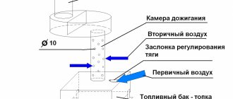
What happens when fuel burns? Heat is released and combustion products are formed - steam, gases and solids. We call the latter soot, soot , and all together - smoke . At the moment of leaving the furnace, this mixture is also heated to several hundred degrees. And if some heat-intensive obstacle , all this heat will simply fly away into the chimney to increase the greenhouse effect on our planet.
However, once upon a time, not only were there no obstacles, but there were no pipes either. Because they weren’t made from wood! Therefore, the first type of stove according to the method of removing smoke is chimneyless, “black” .
In its simplest version, it is a pile of stones placed in a vault over a fire . In the modern version, it is a brick hearth that keeps the same pile of stones from spreading. But the principle is the same: light a fire under the stones, wait for the wood to burn out, release the smoke outside through a window or door - and you can steam by pouring water on the heated stones.
Then a smoke collector - akin to a kitchen hood - also separated from the stove. A similar option can still be found in the bathhouse today.
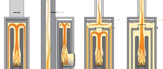
Then the chimney pipe . And if it is simply inserted into the stove (into the firebox or heater - it doesn’t matter), then such a stove will be called direct-flow . Heat here is not taken from the furnace gases, so it has the lowest efficiency.
But heat is a pity, so the inventors’ idea went this way: what if we increase the path that the smoke travels inside the stove? smoke circulation system appeared , where smoke is forced to run with obstacles inside channels that lead it up and down, or horizontally to the right and left. The system is excellent for heat extraction, but it has its drawbacks - the channels, especially horizontal ones, must be cleaned regularly , otherwise there will be no draft.
An alternative to the smoke circulation system was the bell-type stove . It has no channels and is practically independent of traction. Hot furnace gases, leaving the firebox, end up under the hood, where they actively share heat with the furnace mass. New portions of hot furnace gases rise, displacing cooled ones down and into the chimney.
However, everything that has been said about the chimney primarily applies to brick stoves . It's rare to see a metal stove with smoke circulation. Usually they are primitive - direct-flow, except that they have flame dividers. And their sizes are much smaller than brick ones, there are no passages, and there is no heat-intensive material - where to take the heat?
The stove ends at the chimney. What remains optional is a tank or heat exchanger , which can also be indicated on the diagram of the sauna stove. But it is better to talk about this when analyzing specific structures, to which, in fact, we are moving on.
Mortar for laying the stove
The thinness and elasticity of the composition and the absence of cracks after drying are important. You can use a ready-made mixture from the store or make it yourself. For this you need purified clay. It needs to be soaked in water, and after a day kneaded with sand - first, several variations of the solution are made for testing, changing the proportions. From each they form cakes, 1 cm thick. After 2-3 days they are examined - where there are fewer cracks, the composition is better.
To ensure uniformity of the clay, after soaking it is wiped through a mesh with 0.5 cm cells. When preparing the solution for the firebox, it is better to replace ordinary sand with fireclay powder. Mix it with clay 1:3(4).
Schemes of brick mini-ovens
Small ovens occupy a small area; the dimensions of their bases range from 50 to 70 centimeters in width and up to 65–100 cm in length. The height of the heating structure is from 1.5 to 2.3 meters. A cooking floor, an oven, and a water heating tank are built into the oven. Stove makers have also developed devices intended only for heating a home.
Small heating structure
This is the simplest heating structure. We will analyze the model in the following sizes:
- base width - 51 cm;
- base length (depth) - 89 cm;
- height - 238 cm.
The mini-stove is installed in the middle of the kitchen or against the wall. The optimal heating area is 20-35 meters. Interior partitions are erected around the stove, which allows heating both the kitchen and the adjacent room.
Inside the device are:
- combustion chamber;
- blower;
- smoke channels leading into the chimney.
The combustion door of the mini-stove (cast iron or glass) is selected depending on the aesthetic preferences of the home owners. A door made of heat-resistant glass, through which you can see how the wood is burning, gives the structure a resemblance to a fireplace. Two smoke valves are installed in the middle and upper parts of the furnace. There is one door for cleaning the channels. To build this model of the device you will need:
- 260 pieces of ceramic bricks;
- 130 pieces of fireclay bricks;
- grate (40x23 cm);
- combustion (30x20 cm) and blower (20x14 cm) doors;
- 2 doors for cleaning holes (20x40 cm);
- metal pre-furnace sheet (50x70 cm);
- two sheets of roofing material measuring 60x100 mm;
- sand and clay (or ready-made clay-sand mixture for masonry), clay-fireclay mixture.
Reference. Masonry mortar increases the volume of the device by the thickness of the joints.
The base and top of the mini-oven are laid with ceramic bricks on a clay-sand mortar. The firebox is made of fireclay bricks on a clay-fireclay mixture.
Three and a half bricks fit on the long side of the base, and 2 standard bricks 25 cm long on the short side. The masonry consists of 35 rows in height.
Small heating and cooking stove
This is a mini-oven model for heating and cooking - a convenient and very compact structure. The optimal area for a heated room at sub-zero temperatures is 20-25 square meters.
The device has the following dimensions:
- base length (depth) - 64 cm;
- base width - 51 cm;
- height - 215 cm.
The structure is being erected in the kitchen. The device includes:
- blower;
- combustion chamber;
- smoke channels leading into the chimney;
- cooking floor;
- niche for the oven.
The cast iron cooking floor has a hole that is closed with a disk and a circle. Solid flooring is also available for sale. In the niche for the oven chamber there is a metal oven or a hot water tank with a tap. If the niche is left free, it is used for drying things. To build a stove you will need:
- 222 pieces of ceramic bricks;
- grate (40x25 cm);
- firebox door (20x20 cm);
- door for the blower (14x14 cm);
- cooking floor (35x38 cm);
- metal oven or hot water tank;
- iron pre-furnace sheet (50x70 cm);
- two doors for cleaning holes (20x14 cm);
- two valves;
- a piece of flat slate;
- steel corner;
- clay, sand or ready-made clay-sand mixture for masonry.
Arc furnaces
The first electric arc furnace was installed in Russia.
Furnace structure. The oven has a working window and an outlet with a drain chute. The furnace is powered by three-phase alternating current; the metal is heated and melted by powerful electric arcs burning between the ends of three electrodes and the metal in the furnace. The furnace rests on two support sectors that roll along the frame.
The tilt of the furnace towards the outlet and the working window is carried out using a rack and pinion mechanism. Before loading the furnace, the arch suspended on chains is raised to the portal, then the portal with the arch and electrodes is turned towards the drain chute and the furnace is loaded with a bucket of metal.
Electrode holders are used to supply current to the electrodes and to clamp the electrodes. The heads of the electrode holders are made of bronze or steel and are cooled with water, since they are highly heated by both the heat from the furnace and the contact currents. The electrode holder should clamp the electrode tightly and have low contact resistance.
Currently, the most common spring-pneumatic electrode holder. The electrode is clamped using a fixed ring and a clamping plate, which is pressed against the electrode by a spring. The plate is pressed away from the electrode and the spring is compressed using compressed air.
The electrode holder is mounted on a metal sleeve - a console, which is attached to an L-shaped movable stand into one rigid structure. The movable post can move up or down inside the fixed box post. Three fixed posts are rigidly connected into one common structure, which is located on the platform of the furnace support cradle in a state of rest before switching on. The movement of movable telescopic racks occurs either using a system of cables and counterweights driven by electric motors, or using hydraulic devices.
The mechanisms for moving the electrodes should ensure their rapid lifting in the event of a charge collapse during the melting process, as well as a smooth lowering to avoid their immersion in the metal or impacts on unmelted pieces of the charge. The raising speed of the electrodes is 2.5–6.0 m/min, the lowering speed is 1.0–2.0 m/min.
During melting, the electrodes cut three wells in the charge, at the bottom of which liquid metal accumulates. To speed up the melting, the furnaces are equipped with a rotating device that turns the body in one direction and the other at an angle of 80°. In this case, the electrodes cut nine wells in the charge. To rotate the furnace body, lift the roof, raise the electrodes above the charge level and turn the body using a ring gear attached to the body and gears. The furnace body rests on rollers.
Current is supplied to the melting space of the furnace through electrodes assembled from sections, each of which is a round billet with a diameter of 100 to 610 mm and a length of up to 1500 mm. In small electric furnaces, carbon electrodes are used, in large ones - graphite. Graphite electrodes are made from low-ash carbon materials: petroleum coke, resin, sand. The electrode mass is mixed and pressed, after which the raw workpiece is fired in gas furnaces at a temperature of 1300 °C and undergoes additional graphitizing firing at a temperature of 2600–2800 °C in electric resistance furnaces. During operation, as a result of oxidation by furnace gases and atomization during arc combustion, the electrodes burn out.
As the electrode shortens, it is lowered into the furnace. In this case, the electrode holder approaches the arch. There comes a point when the electrode becomes so short that it cannot support the arc, and it must be extended. To extend the electrodes, threaded holes are made at the ends of the sections, into which an adapter-nipple is screwed in, with which the individual sections are connected. Electrode consumption is 5–9 kg/t of steel produced.
An electric arc is one of the types of electrical discharge in which current passes through ionized gases and metal vapors. When the electrodes briefly approach the charge or each other, a short circuit occurs. A high current flows, the ends of the electrodes become white hot. When moving the electrodes apart, an electric arc occurs between them. Thermionic emission of electrons occurs from the hot cathode, which, heading towards the anode, collide with neutral gas molecules and ionize them. Negative ions are directed to the anode, positive ions to the cathode. The space between the anode and cathode becomes ionized and conductive. Bombarding the anode with electrons and ions causes it to heat up greatly. The anode temperature can reach 4000 °C. The arc can burn on direct and alternating current. Electric arc furnaces operate on alternating current. An electric arc furnace using direct current was built in Germany.
In the first half of the period, when the electrode is the cathode, the arc burns. When the polarity changes, when the charge—metal—becomes the cathode, the arc goes out, since in the initial period of melting the metal is not yet heated and its temperature is not enough to emit electrons. Therefore, in the initial period of melting, the arc burns restlessly and intermittently. After the bath is covered with a layer of slag, the arc stabilizes and burns more evenly.
Electrical equipment. The operating voltage of arc furnaces is 100–800 V, and the current is measured in tens of thousands of amperes. The power of a separate installation can reach 50–140 MV ∙ A. A current voltage of up to 110 kV is supplied to the substation of the electric steelmaking shop. High voltage powers the primary windings of furnace transformers.
The electrical equipment of an arc furnace includes the following devices intended for carrying out repair work on the furnace.
- Air disconnector - designed to disconnect the entire electric furnace installation from the high voltage line in time.
- Main circuit breaker - serves to disconnect under load an electrical circuit through which high voltage current flows. If the charge is not placed tightly in the furnace at the beginning of smelting, when the charge is still cold, the arcs burn unstably, the charge collapses and short circuits occur between the electrodes. In this case, the current strength increases sharply. This leads to large overloads of the transformer, which may fail. When the current exceeds the set limit, the circuit breaker automatically switches off the unit via a signal from the overcurrent relay.
- Furnace transformer - necessary to convert high voltage to low voltage (from 6–10 kV to 100–800 V). The high and low voltage windings and the magnetic circuits on which they are placed are located in a tank with oil, which serves to cool the windings. Cooling is created by forced pumping of oil from the transformer casing into the heat exchanger tank, in which the oil is cooled with water. The transformer is installed next to the electric furnace in a special room. It has a device that allows you to switch the windings in stages and thus stepwise regulate the voltage supplied to the furnace. Thus, a transformer for a 200-ton domestic furnace with a power of 65 MV ∙ A has 23 tension stages, which are switched under load, without turning off the furnace.
The section of the electrical network from the transformer to the electrodes is called a short network. Feeders coming out of the wall of the transformer substation supply voltage to the electrode holder using flexible water-cooled cables. The length of the flexible section should allow the desired tilt of the furnace and the opening of the roof for loading. Flexible cables are connected to copper water-cooled bars installed on the sleeves of the electrode holders. The pipe tires are directly connected to the electrode holder head, which clamps the electrode.
In addition to the indicated main components, the electrical network includes various measuring equipment connected to the current lines through current or voltage transformers, as well as automatic control devices for the smelting process.
Automatic regulation. As melting progresses, varying amounts of energy are required to be supplied to the electric arc furnace. You can change the power supply by changing the arc voltage or current. Voltage regulation is carried out by switching the transformer windings. The current is regulated by changing the distance between the electrode and the charge by raising or lowering the electrodes. In this case, the arc voltage does not change. The lowering or raising of the electrodes is carried out automatically using automatic regulators installed at each phase of the furnace. In modern furnaces, a given electrical mode program can be set for the entire melting period.
Device for electromagnetic mixing of metal. To mix metal in large arc furnaces, to speed up and facilitate the technological operations of downloading slag, an electric winding is installed in the box under the bottom of the furnace, which is cooled with water or compressed air.
The stator windings are powered by a low frequency current from a two-phase generator, which creates a traveling magnetic field that captures the liquid metal bath and causes the lower layers of metal to move along the furnace bottom in the direction of the field movement. The upper layers of metal, together with the slag adjacent to it, move in the opposite direction. In this way, the movement can be directed either towards the working window, which will facilitate the exit of slag from the furnace, or towards the drain hole, which will favor the uniform distribution of alloy steels and deoxidizers, averaging the composition of the metal and its temperature.
Operating the device
After the structure is laid out, it is dried. In summer it will take 2 weeks. If the masonry was carried out in the autumn-winter period, they begin to heat the stove with small wood chips for 30 minutes once or twice a day. For additional ventilation, all cleaning doors and latches are opened (if it rains, they are not opened).
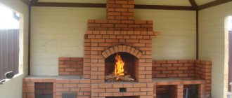
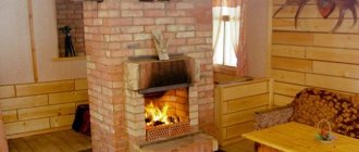
Photo 2. Finished 3 by 3 brick oven. The device is installed near the wall and has a very compact size.
When wet spots disappear from the surface and condensation stops falling on the metal elements, the structure is dry. After this, a control fire is carried out - the furnace is heated at full strength for several hours at maximum draft. If no cracks have formed in the masonry in the area of the firebox (small spiderweb cracks are acceptable), then the stove is ready for use.
Attention! You cannot immediately heat the stove too much - this will cause cracking of the masonry and render the structure unusable even before operation begins. As a result, the entire construction phase will take an average of 1 month:
As a result, the entire construction phase will take an average of 1 month:
- foundation preparation - 10 days;
- laying the stove and chimney - 1-2 days;
- drying of the structure - 14-21 days, depending on the time of year.
After this period, if no shortcomings have been identified, you can start heating the stove at full capacity.
How to light a wood stove
To effectively use a wood-burning stove, you must fire it using the laws of physics and common sense. It is inappropriate to use the word “correctly” here, because it is the rules for safety reasons that require firing at maximum draft.
Effect of traction
In fact, it is precisely the regulation of draft that allows you to achieve the maximum positive effect from the firebox. By reducing thrust, you can reduce the intensity of fuel combustion. In this case, the stove array will receive the same amount of heat over a certain period of time as at maximum draft, but the wood will burn a little longer.
Covering the vent to reduce the intensity of combustion, as many believe, is inappropriate - the combustion will slow down, but only because there is not enough oxygen for the process. But it is its presence in the firebox that increases the temperature of the flame. Accordingly, when the ash door is closed, the firewood will simply smolder, releasing a minimum of heat. In addition, with such a firebox, soot settles on the walls of the chimney due to the fact that the flue gases have a low temperature, insufficient for the self-cleaning process of the pipe.
The negative impact of a loosely closed firebox door or the presence of gaps between it and the masonry on the quality of firewood combustion is a controversial issue. In a well-built stove, air will be drawn into the combustion chamber through the door, thereby increasing the temperature of the flame, but this will not in any way reduce the quality of the firebox. Another thing is fire safety. You need to heat with the door tightly closed.
What fuel to use
Firewood must be stored in a woodshed so that it is always dry.
To fire the stove, you must use well-dried firewood from deciduous wood - alder, aspen, birch. Damp wood will burn poorly, producing a large amount of steam, which prevents smoke from escaping from the stove. Birch firewood produces a large amount of heat when burned, but damp logs contribute to the release of tar, which, settling on the walls of the chimney, worsens the performance of the stove.
To constantly use the stove for heating, you need to take care of creating a supply of dry firewood in advance, before the start of the cold season. In order not to be left without dry firewood in the winter, it is better to prepare it in the spring. Recently, a relatively new type of fuel has appeared on sale - wood waste - shavings and sawdust, formed into fuel briquettes. The calorific value of such fuel is greater, it is always ready for use, but its price is higher than that of firewood.
Fire order
To light the stove, you first need a small amount of fuel - place firewood or briquettes in the center of the grate. If the stove has not been fired for a long time, it will not be possible to immediately generate draft in the chimney. A large load of fuel will generate a lot of smoke, which will come out of the firebox and enter the room through the door of the firebox and vent. To prevent this from happening, you must first burn a small amount of fuel in the firebox, for example, a rolled-up newspaper.
When the draft appears, you can light the wood with the valve fully open. Until the flame engulfs the entire stack of firewood, it is not recommended to open the firebox door, stir the firewood, or close the valve. After the entire fire has flared up, you can gradually close the valve, limiting the draft. This must be done carefully so that smoke does not go into the room, which can happen if there is not enough draft. The flame should not consume the wood with a bang, humming in the chimney, but burn steadily and calmly. Then the maximum amount of heat will remain in the oven and will not fly outside.
To add fuel to the stove, you first need to close the ash door and then open the fire door. This will prevent smoke from escaping into the room. If a large amount of fuel is added, you can open the valve slightly, but the best result will be if you add firewood in small quantities, but often. After the firebox door is closed, the ash pan must be opened.
As the fuel burns, you need to close the valve. You can close it completely only when there is not a single smoldering coal left in the firebox. Otherwise, carbon monoxide will enter the room and may cause poisoning to those present. After finishing the fire, it is necessary to thoroughly ventilate the room using ventilation to remove any remaining smoke that may have come from the stove while the fuel was burning. It is not recommended to open the stove until the next fire.
Oven care
In order for the wood-burning stove to always operate efficiently and smoothly, you must follow simple operating rules:
- promptly remove ash from the ash pan and ash pan for better air supply to the firebox;
- control the performance of valves, doors, grates, since the presence of draft and the tightness of the furnace closure depend on this, as well as the creation of conditions for efficient combustion of fuel;
- clean chimneys, as channels clogged with soot impair draft.
Brush for mechanical cleaning of the chimney
The ash is simply removed using a stove scoop. The serviceability of stove casting is checked by inspection, but with chimney channels everything is much more complicated. It is possible to discover that they are clogged with soot only when the draft has already decreased so much that it will be difficult to light the stove. Then mechanical cleaning of the canals using special tools will be required. To prevent this, you just need to follow three simple rules:
- do not heat the stove with raw firewood or cuttings of softwood lumber, and do not burn household waste in the stove;
- always keep the vent open while burning;
- Do not finish firing the stove until the chimney has warmed up.
As a preventative measure to prevent the formation of soot in the chimney, it is advisable to burn several aspen logs or some potato peelings at the end of the firebox. Aspen will provide a high temperature at which the soot simply burns out, and the starch contained in the potatoes, together with the steam, will soften the deposits, which will subsequently simply fly out through the pipe in large flakes.
Table salt gives a good result for protecting the chimney from soot deposits - just throw a handful of it directly onto the burning wood. This method will not help to clear the soot layer, but it will certainly prevent the formation of new layers.
Features of the order of brick stoves
Stoves often serve as interior decoration, so they are lined with clinker, tiles, and tiles. The diagonals in the first row are carefully measured, and a plumb line is hung in the center of the chimney, which is removed on the last rows of the pipe. Also, the diagonals are controlled every 4 rows, and on each row a cord is pulled during installation, which is checked by the rule. Instead of cement-sand mortar, it is recommended to use clay, regardless of the type of furnace being built. Ready-made dry solutions significantly save time spent on clay preparation. To prevent the composition from drying out quickly, the brick must be moistened with water before laying.
Operating costs will be lower if there are no rectangular ledges inside the structure. For this purpose, when creating an overlap (ledge), the stone is tried on without mortar, the overlap line is outlined, and the excess material is cut off with a grinder. Internal seams during laying are regularly checked, and excess mortar is removed from time to time. The pipe is cleaned after completion of the work.
Brick kilns are made of several materials:
- external cladding;
- masonry bricks (main structure);
- fireclay – fireproof material is used to lay out areas exposed to strong heat (furnace, under);
- bricks with high-density edges are located inside the oven.
Clay bricks should not be mixed with fireclay, and ovens, hobs, rods and grates, and water tanks should not be embedded in the masonry - this is due to different expansion coefficients when heated. If metal elements are rigidly embedded in the masonry, the structure will soon collapse.
Characteristics of stove heating
Fuel is burned periodically in the furnace, so heat enters the room unevenly, and an unsteady thermal regime is observed in it. The greatest heat transfer from the furnace occurs at the end of the firebox, when the temperature of its walls reaches its maximum. The lowest heat transfer refers to the time before the start of the next fire.
The change in heat supply to the room is characterized by the heat transfer unevenness coefficient of the furnace, which expresses the ratio of the half-difference between the maximum and minimum heat transfer of the furnace to its average value. The heat transfer unevenness coefficient depends on the number of fireboxes per day and is determined experimentally for each furnace design.
Fluctuations in heat supply cause changes in air temperature and radiation temperature of the room. With stove heating, there is a constant change in the temperature of the room, depending on its heat resistance. As is known, the greater the ability of the fences and equipment of a room to absorb heat, the higher its thermal resistance. A room in which, with a heating furnace that transfers heat unevenly, provides air temperature fluctuations within ±3 °C, is considered sufficiently heat-resistant.
Stove heating is also widely used today as electric floor heating. In Russia, almost a third of the housing stock (mainly due to old houses in rural areas) is equipped with stoves. During new capital construction, stove heating is used to a limited extent.
According to current standards, the use of stoves for heating industrial premises of categories A, B and C is not allowed. The installation of stove heating in cities and urban-type settlements must be specifically justified.
Stove heating is allowed in residential and administrative buildings with no more than two floors (not counting the basement), small public buildings (for example, in secondary schools with no more than 80 seats), industrial premises of categories G and D with an area of no more than 500 m2. Stove heating is often installed in garden houses.
The spread of stove heating is explained by its advantages: lower cost of the device compared to other types of heating, low consumption of metal (only for the grate, doors, valves, sometimes on the frame), simplicity of design and maintenance, independence of heating of individual rooms, and simultaneous provision of ventilation of the rooms.
| Advantages | Flaws |
| The advantages of stove heating indicate its wide availability. However, the restrictions placed on further expansion (note again that stove heating is sometimes allowed but never recommended) reflect its serious disadvantages. | Disadvantages of stove heating: reduced level of thermal comfort compared to water heating (unsteady thermal conditions, as well as overcooling of the lower zone of the room), difficulties during operation (concerns about fuel, stove care, room contamination), increased fire danger, possibility of carbon monoxide poisoning If the stove is not properly maintained, loss (up to 5%) of the working area of the room. |
Picture 1. Direction of air movement in the room when the heating stove is located near the inner wall
When heating with stoves, stoves are usually placed in rooms near internal walls, using these walls to lay smoke channels. However, when designing stove heating, one should strive for a minimum number of heating devices (about their placement) through their rational placement. The principle should be observed in which the heat transfer of the part of the heated furnace exiting into each room would completely compensate for its heat losses (Figure 3). At the same time, it is easier to remove smoke channels into the atmosphere, the length of the heads (sections of the channels above the roof) is reduced, which improves draft in the furnaces. However, with this arrangement of furnaces, the lower zone of the premises is supercooled. Air flows, heated at the surface of the furnace, rise to the ceiling of the room. Air flows, cooling at the surface of the outer enclosures, descend to the floor. The air circulation shown in Figure 1 is installed in the room. As a result, cooled air moves along the floor towards the stove, disrupting the normal well-being of people in the room.
This circulation of cold air over people's feet can be avoided by moving the indoor stove to an outdoor enclosure. But in this case, it will be necessary to insulate the smoke ducts in the external walls to avoid condensation on their inner surface of moisture from the exhaust flue gases. At the same time, deterioration in draft in the furnace and additional contamination of the room when transferring fuel, ash and slag are inevitable.
When installing stove heating, the removal of flue gases into ventilation ducts, as well as the installation of ventilation grilles on smoke ducts, are not allowed.
Consequently, the channels of both systems - stove heating and natural exhaust ventilation - must be separated in order to avoid disruption of their operation.
Figure 2. Optimal placement of the stove in a three-room apartment.
The stoves in the building are placed so that one stove heats no more than three rooms located on the same floor (Figure 2). In a building with a corridor system for connecting rooms, the stoves are installed in such a way that servicing is carried out from corridors or utility rooms that have windows with vents and are equipped with natural exhaust ventilation. In two-story buildings, two-tier stoves can be installed, either separate or with one common firebox on the ground floor.
Figure 3. Options for placing heating stoves: A - in the center, or with a slight offset from the center; B - angular placement of the furnace; B - wall placement of the furnace with fans to create heat flows; 1 - oven; 2 - fans; 3 - warm air flows.
Buslaevskaya stove: projects
The design has a built-in hood. The oven is small in size. It is ideal for any private home, as it allows you not only to heat the premises, but also to cook food. Despite its compact size, the stove heats spacious rooms well, which is why there are ready-made designs for houses with a stove.
Special schemes for laying brick stoves will help you complete the work without carrying out complex calculations.
For installation you will need the following materials:
- doors - firebox (0.2x0.25 meters), VK (0.39x0.5 meters), blower (0.14x0.14 meters);
- refractory - 43 pieces;
- solid brick – 382 pieces;
- oven-cabinet 28x33x50 centimeters;
- cast iron stove 0.7x0.4 meters with burners (removable rings of different diameters);
- valves - steam exhaust (12x13 centimeters) and smoke (12x25 centimeters);
- grate - grate 30x20 centimeters;
- corner - three equal-flange blanks 1 meter long and 45x45 millimeters in size;
- steel - piece 0.3x0.28 meters;
- strip - 4 pieces of meter (4 graph paper), 0.25 meters (2 graph paper), 0.35 meters (3 graph paper);
- cast iron plate – 0.4 x 0.25 meters; 40x15 centimeters.
Projects for brick stoves of this type look like this:
- Full row.
- Blower door.
- Window opening for cleaning.
- The bottom of the oven is lined with refractory, three sides are lined with iron.
- Installation of the combustion door, grate, refractory under the firebox, cleaning cover, ash door.
- Installation of DS.
- Laying refractory on the edge around the door.
- Laying according to the scheme.
- The oven is top coated with clay (1 centimeter), the heater is covered, and a stove with burners is attached.
- Installation of smoke circulation with cleaning windows, the stove is not laid. Subsequently, the brick is placed on its edge.
- The cleaning is overlapped, channels are created, and 25-centimeter strips are laid.
- The cleaning is completed and the fastening wire is installed.
- The cap is installed.
- Installation of the VK ceiling, while the hoods remain.
- The stoves are laid out according to the diagram.
- The small stove ends in sheet iron, the masonry is done in the same order as a brick stove.
- The cleaning hole of a large stove is laid out, the edges of the side walls of the channels are cramped.
- Laying protrusions.
- The projections are duplicated and the corner is installed.
- The BP chimney is closed in the same way as row 19.
- A three-row neck is made, the size of the chimney is reduced to a section of 26x13 centimeters for the top valve.
- A chimney is created with grooves on this and subsequent rows.
The dimensions of the structure increase when using clinker facing bricks, so using them instead of solid material is not recommended. When finishing with tiles, durability is ensured (the material lasts for decades), in addition, it can be dismantled for cladding other heating structures.
Popularity of brick kilns
Unlike many heating methods, a brick stove tends to maintain optimal air humidity in the room. It's all about the porous structure of the brick, which, when heated, releases moisture vapor, and when it cools, absorbs it back.
Therefore, in houses with brick stoves, optimal humidity is maintained, which means that such a stove can safely be called environmentally friendly. Needless to say, brick, clay and other oven materials are natural materials that are safe for health.
Thanks to the breathable structure, in a house with stove heating you can feel comfortable already at 18–19 degrees, whereas with other types of heating devices it is 20–22. This is a significant saving, but not all. The stove is inherently omnivorous and can work on anything that can burn - coal, firewood, pellets, etc.
Some types of stoves, such as Kuznetsov’s brick stoves, made like a bell, provide such efficiency indicators (80–95%) that they can compete with the most economical Buleryan stoves.
House layout
Initially, the house plan should take into account the stove - you can come up with many interesting masonry for different types of brick structures. Other things to consider when planning your home:
- For a stove with 500 bricks or more, with its own chimney, you need to lay an independent foundation, which should not be connected to the main foundation of the house - have a certain distance from it.
- Some stoves, such as a low, wide-width hob with a heating panel that can withstand from 250 kg/sq. m (according to SNiP requirements) can be installed without a foundation. You just need to provide thermal insulation and strengthen the flooring with additional joists.
- Ceiling beams should not touch the chimney, and the chimney should be half a meter or more higher than the ridge of the roof, and the distance between them should be at least one and a half meters.
As a matter of fact, almost all stoves require from 1 thousand to 1.5 thousand bricks, so you need to count on a separate foundation. There may be some exceptions to the foundation plan in the case of a sectional strip foundation of the main building.
It is possible to find a place in the plan of such a house and lay the foundation of the stove at the intersection of the ribbons - under the internal walls. But to other fragments of the main foundation there should be no less than 1.2 m.
How to properly build a brick oven. Instructions for the progress of work
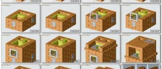
Before starting work, you should familiarize yourself with the procedure for the selected type of oven. Visual diagrams will tell you in what order to lay the bricks.
After choosing the type of rough stone and its arrangement, you can proceed to instructions on how to build a brick stove in your house. This step-by-step guide is suitable for those who would like to get oven equipment with a hob.
- Rows of bricks are laid in a continuous row on cement-sand mortar up to floor level. The masonry must be adjusted precisely by level and plumb so that it is level and strong. The stability of the structure depends on this.
- After the first row has been laid, they begin to install the blower chamber.
- Before laying the second row of bricks, install the door for the blower. There are special loops in its corners; steel wire is threaded through them and laid into the seams of the masonry. To prevent it from moving or turning over, it is supported with bricks (but not treated with mortar; this is a temporary measure).
- The second row is laid as shown in the order. A ash pit is formed.
- Next, fireclay is used, indicated in the diagrams in yellow. After laying, a grate is installed above the ash pit.
- On the fourth row of bricks, they begin to lay out two channels to clean the rough from accumulated soot. Each chamber is equipped with a separate door.
- A grate is placed in the fifth row. It can be correctly laid in the special recesses that are in the bricks of the bottom row. All subsequent rows must be laid with fireproof bricks.
- The grate will fit correctly only if it is laid accurately. Each row must be checked with a level.
- Before laying the sixth row, the combustion door is installed. It is temporarily fixed with a column of bricks, which is laid on the grate. To prevent it from falling out, you can support the part with a metal or wooden strip.
- From the seventh row, the creation of gas ducts begins. To do this, the vertical walls are laid with bricks installed on the edge.
- Before laying the ninth row, a quarter is knocked out of the brick. It is laid in such a way that it fixes the firebox door. The wire from it is laid in the same row of masonry, which helps to finally secure it.
- If a hob is being made for working with cauldrons or other utensils, it is laid in the 11th row. Bricks are laid on the upper opening, the front part is decorated with a steel corner. The sealant is basalt cardboard or asbestos cord.
- Rows 12-16 are a chamber above a cast iron stove. Before you begin to cover the cooking niche, you need to lay steel strips. They will be the basis for laying the 17th row.
- The front part of the 17th row needs to be additionally decorated with a metal corner.
- The 18th and 19th rows are laid out completely, three vertical heat exchangers are installed.
- 20th row of masonry - placement of horizontal channels and doors for regular cleaning of the stove from carbon deposits and soot. From this moment the construction of the drying chamber begins, if provided.
- 22nd row – door overlap.
- From the 23rd row they begin to work with a horizontal flue. At this stage, it is ensured that only the holes in the vertical channels are open. Metal strips are laid over the drying chamber.
- The 24th row of bricks is laid.
- In row 25-28, another door for the cleaning channel is installed. At this point, you can block the stove niche.
- Valves are installed on the two remaining vertical gas ducts. First the frames are installed, then the partitions.
- Rows 31-35 become a transition area to the chimney.
- In the area of the 36-38th row, fluff is made.
This completes the installation of the brick stove with your own hands. Next you need to move on to constructing the chimney. It is laid out from the first row of the rough and finished where indicated in the order. In the example given, this is the 26th row. If necessary, the chimney is made higher.
In the third row of the chimney you need to install a special door. It is necessary in order to clean it from combustion products. On the 27th they install a central damper. Starting from the 31st row, the cross-section begins to gradually decrease so that the pipe can be taken outside.
In the place where the pipe from the furnace will pass through the ceiling, you need to lay a layer of non-combustible material. Expanded clay and mineral insulation are usually used.
Furnace arrangement options
These are the main popular options. It is worth carefully reviewing the diagrams before starting construction work - they show step by step how and in what sequence materials should be placed.
- The order of the Swedish oven.
- Dutch order.
- Order of the Russian stove.
- Ordering a sauna stove.
- Ordering of the Kuznetsov furnace.
Briefly about the installation of the oven and heat exchange register
Some designs provide for the installation of an oven. It needs to be mounted in a place where it would be washed by the maximum amount of heat flow. The optimal zone is the transition from the firebox to the heat exchanger. Metal corners are placed on the side walls of the horizontal flue. At the points where the oven touches the wall, asbestos cord or basalt cardboard is laid as a seal.
The heat exchange register is placed in the hottest zone of the stove. It can be located at the beginning of the flue, in the rear part of the firebox or under the hood (for non-revolving options).
Assembling a brick stove for a private home is not a difficult task. If you have the necessary tools, diagrams and quality materials, you can make a productive and durable roughener for regular use.