Hydrotesting is a series of testing activities carried out in accordance with the provisions of building codes. During the work, the tightness, strength and volume of the system are determined, the compliance (or non-compliance) of pipe products with the requirements specified in the regulatory documentation is established, and all defects in the systems are identified at the stage of their installation and operation.
Test methods for heating systems
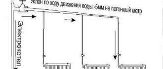
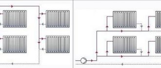
Installation and diagrams of heating systems
Every developer is aware of the need to test the heating system. SNiP regulates this procedure depending on the configuration and complexity of the heating circuit.
This publication will discuss in detail the main methods for testing centralized and autonomous heating systems (HS) of apartment and private buildings.
Purpose of the work
In accordance with regulatory documents, after completion of installation work and thorough flushing of in-house CO, the following checks must be performed:
- The functionality and correct installation of each individual element of the system.
- For compliance with design parameters for pressure and thermal loads.
CO testing is carried out using one of two main methods:
- Pressure testing using hydrostatic method.
- Manometric method (Compressed air).
Hydraulic and pneumatic tests are used to test CO for leaks. Thermal tests of heating systems must be carried out to verify compliance with the calculated thermal power, correct and uniform heating of radiators and piping.
Hydrostatic CO testing
The hydraulic test of the heating system is as follows: from the lowest point on the return pipeline (return), the route is filled with liquid (water). This allows air to be removed most effectively through open (automatic) air vents and an expansion tank. This type of CO testing is considered completely safe, since it is “run in” under the closest operating conditions. It should be understood that in the event of an emergency (depressurization of the route), flooding of the premises is possible.
The work is carried out in two stages:
- Water supply under pressure equal to 1.25 of the calculated values. For correct measurements, the pressure in the pipeline should not be less than 1.5 MPa. This stage is considered successful if the pressure in the pipeline does not drop by more than 0.5 kg/cm2 for 10 minutes or more.
- At the second stage, testing is considered successfully completed if the pressure in the circuit does not change in the next 120 minutes. or its fall does not exceed 20 kPa.
Important: hydrostatic testing is carried out without a heat generator and expansion tank.
Steam CO is checked exclusively by the hydrostatic method. If the calculated parameters correspond to 0.07 MPa, then testing is carried out with a water pressure corresponding to 0.25 MPa.
Pumps are tested only when the pipeline is filled with water. Initially, the pump is started at idle for 35 minutes, then under load for 10-20 minutes. The test is considered passed if the pump operates in cycles: 1 hour and 6 hours without critical heating and the appearance of extraneous noise.
To check the elevator unit, an initial pressure of at least 10 kg/cm 2 should be used. Upon successful testing, he is promoted to worker. Testing of heating system pipelines should be carried out in compliance with the conditions regulated by the operating rules for power installations No. 115, namely:
- The liquid with which the circuit is filled must have a temperature no higher than 45°C, and the air in the room must not be lower than + 5°C.
- Pressure 1.25 from working.
After 10 minutes in this mode, the pressure is reduced to operating parameters and sufficient time is maintained to inspect the route (seams, pipe joints, fittings, etc.).
Important! The pressure drop in panel COs must be 10 kPa or less; in CO made from polymer materials – 60 kPa, in the next 30 minutes.
After completion of the work, the circuit is washed. Water is discharged through a coupling located at the bottom of the pipeline. The final stage is the process of filling out a hydraulic test report for the heating system.
Procedure for hydrotesting
In accordance with the standards, the check is carried out in a certain sequence:
- network cleaning;
- installation of taps and pressure gauges;
- ensuring water supply;
- filling a separate area with water to the required level;
- marking defective areas of the pipeline;
- repair of identified problems;
- re-inspection after repair work;
- disconnecting the tested area from temporary communications, removing water from the pipeline;
- dismantling of measuring instruments, taps and plugs.
Testing heating systems for strength and tightness using the crimping method
Pressure testing of the heating system (hereinafter referred to as HS) of a residential building is an effective way to check its performance by testing the strength of all structural elements of the structure and monitoring the tightness of the interconnected connections of the system elements.
The technician performs pressure testing of the heating system
Goals and objectives of CO crimping
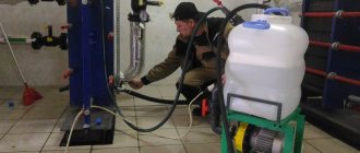
Heating systems using water coolant or antifreeze are complex multi-element structures operating under pressure. Testing of water systems is carried out by the pressure testing method, which consists in creating excess pressure as close as possible to the normalized limit pressure parameter. This simulates an emergency situation that could occur under existing operating conditions. Excess pressure is pumped into the system in two ways:
- air when pumped from an air compressor;
- water when supplied from a hydraulic pump.
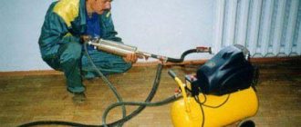
It is preferable to carry out pneumatic tests in cold months to prevent moisture in the heating system from freezing if any problems occur in it.
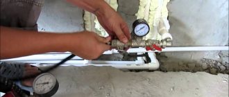
The figure below shows the working moment of pneumatic testing of pipeline communications with air from an electric compressor.
CO pressure testing using an electric compressor
The purpose of carrying out pressure testing measures for domestic heating systems is:
- checking the tightness of the installation assembly of pipelines and heating devices;
- assessment of the quality of connections of functional elements of the CO to confirm its further performance;
- identification of hidden defects in the installation of communications that provoke leaks in connections or destruction of CO elements;
- checking the mechanical strength of components and parts of CO under excess pressure.
During pneumohydraulic testing with air or water, parts with internal defects will fail, while serviceable components will remain operational.
The list of tasks performed during the heating system pressure testing process includes:
- detection and fixation of places of poor-quality assembly connections, identification of weakened and problem areas;
- identification of violations of the structural integrity of components and parts, detection of mechanical damage or cracking of housings of heating devices;
- analysis of identified defects, troubleshooting;
- documentary evidence of the operability of the water system in the absence of leaks, destruction and other defects.
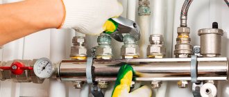
The figure below shows a leak in the connection between the shut-off valve and the pipeline during hydropressure testing of a local CO section.
Manifestation of assembly defects during hydropressing of CO
Regularity of pressure testing
Such a responsible undertaking as pressure testing of heating lines and heating systems in each apartment of an apartment building should guarantee trouble-free operation of water systems throughout the entire heating season. The frequency of pneumohydrotests, the procedure for their implementation and monitoring of the results obtained are regulated by a number of documents at the federal level:
- “Rules for the technical operation of thermal power plants”, approved by the Ministry of Energy on March 24, 2003, regarding the frequency of tests and test pressure parameters - clause 9.2;
- SNiP 3.05.01-85 “Internal sanitary systems” regarding the assessment of the results of hydrotests and air tests - pp. 4.6 and 4.7;
- SNiP 41-01-2003 “Heating, ventilation and air conditioning”, clause 4.4.8 – procedure for conducting hydrotests of water heating systems.
Determination of additional water volume
After performing a leak test, as a rule, the additional volume of liquid in the system should be calculated. This process takes place in the following sequence:
- The pressure level in the structure is again increased by pumping liquid from the measuring tank. The pressure indicator should be the same as during a hydraulic test, that is, exceed the standard indicators by 1.25–1.5 times.
- The time when the leak test ended must be remembered.
- At the third stage, the final water level in the measuring tank is measured.
- Next, the time period that the communication check took (in minutes) is determined.
- Calculation of the volume of liquid pumped from the measuring tank (for 1 case).
- Calculation of the difference between the liquid pumped up and removed from the pipeline (for case 2).
- Calculation of actual consumption of additionally pumped liquid using the formula: qn=Q/(Tk-Tn).
TESTING OF INTERNAL SANITARY SYSTEMS
GENERAL PROVISIONS FOR TESTING SYSTEMS OF COLD AND HOT WATER SUPPLY, HEATING, HEAT SUPPLY, SEWERAGE, DRAINAGE AND BOILER PLANTS
4.1. Upon completion of installation work, installation organizations must carry out:
testing heating systems, heat supply, internal cold and hot water supply and boiler rooms using the hydrostatic or manometric method with drawing up a report in accordance with the mandatory Appendix 3, as well as flushing systems in accordance with the requirements of clause 3.10 of these rules;
testing of internal sewerage and drainage systems with drawing up a report in accordance with the mandatory Appendix 4;
individual tests of installed equipment with drawing up a report in accordance with mandatory Appendix 1;
thermal testing of heating systems for uniform heating of heating devices.
Testing of systems using plastic pipelines should be carried out in compliance with the requirements of CH 478-80.
Tests must be carried out before finishing work begins.
Pressure gauges used for testing must be calibrated in accordance with GOST 8.002-71.
4.2. During individual testing of equipment, the following work must be performed:
checking the compliance of the installed equipment and the work performed with the working documentation and the requirements of these rules;
testing equipment at idle and under load for 4 hours of continuous operation. At the same time, the balancing of wheels and rotors in pump and smoke exhauster assemblies, the quality of the stuffing box packing, the serviceability of starting devices, the degree of heating of the electric motor, and compliance with the requirements for assembly and installation of equipment specified in the technical documentation of the manufacturers are checked.
4.3. Hydrostatic testing of heating systems, heat supply systems, boilers and water heaters must be carried out at a positive temperature in the premises of the building, and cold and hot water supply systems, sewerage and drains - at a temperature not lower than 278 K (5 ° C). The water temperature should also not be lower than 278 K (5 ° C).
INTERNAL COLD AND HOT WATER SUPPLY SYSTEMS
4.4. Internal cold and hot water supply systems must be tested by hydrostatic or manometric method in compliance with the requirements of GOST 24054-80, GOST 25136-82 and these rules.
The test pressure value for the hydrostatic test method should be taken equal to 1.5 excess operating pressure.
Hydrostatic and pressure testing of cold and hot water supply systems must be carried out before installing water taps.
Systems are considered to have passed the tests if, within 10 minutes of being under test pressure using the hydrostatic test method, no pressure drop of more than 0.05 MPa (0.5 kgf/cm 2) and drops in welds, pipes, threaded connections, fittings and leaks are detected water through flush devices.
At the end of the hydrostatic test, it is necessary to release water from the internal cold and hot water supply systems.
4.5. Manometric tests of the internal cold and hot water supply system should be carried out in the following sequence: fill the system with air at a test excess pressure of 0.15 MPa (1.5 kgf/cm 2); if installation defects are detected by ear, the pressure should be reduced to atmospheric pressure and the defects eliminated; then fill the system with air at a pressure of 0.1 MPa (1 kgf/cm2), hold it under test pressure for 5 minutes.
VENTILATION AND AIR CONDITIONING
4.16. The final stage of installation of ventilation and air conditioning systems is their individual testing.
By the start of individual testing of systems, general construction and finishing work on ventilation chambers and shafts should be completed, as well as installation and individual testing of support equipment (electricity supply, heat and cold supply, etc.). If there is no power supply to ventilation units and air conditioning according to a permanent scheme, the general contractor will connect electricity according to a temporary scheme and check the serviceability of the starting devices.
4.17. During individual tests, installation and construction organizations must perform the following work:
check the compliance of the actual execution of ventilation and air conditioning systems with the project (detailed design) and the requirements of this section;
check the air duct sections hidden by building structures for leaks using the aerodynamic test method in accordance with GOST 12.3.018-79, based on the results of the leak test, draw up an inspection report for hidden work in the form of mandatory Appendix 6 of SNiP 3.01.01-85;
test (run in) ventilation equipment with a drive, valves and dampers at idle, in compliance with the requirements stipulated by the technical specifications of the manufacturers.
The duration of the run-in is taken according to the technical specifications or the passport of the equipment being tested. Based on the results of tests (run-in) of ventilation equipment, a report is drawn up in the form of mandatory appendix 1.
4.18. When adjusting ventilation and air conditioning systems to design parameters taking into account the requirements of GOST 12.4.021-75, the following should be done:
testing fans when operating in a network (determining compliance of the actual characteristics with the passport data: air supply and pressure, rotation speed, etc.);
checking the uniformity of heating (cooling) of heat exchangers and checking the absence of moisture removal through the drop eliminators of the irrigation chambers;
testing and adjustment of systems in order to achieve design indicators for air flow in air ducts, local suction, air exchange in rooms and determination of suction or air losses in systems, the permissible value of which is due to leaks in air ducts and other elements systems should not exceed design values in accordance with SNiP 2.04.05-85;
checking the operation of natural ventilation exhaust devices.
For each ventilation and air conditioning system, a passport is issued in two copies in the form of the mandatory Appendix 2.
4.19. Deviations of air flow rates from those provided for in the project after adjustment and testing of ventilation and air conditioning systems are allowed:
Preparatory stage before testing
Before testing the system, the pipes are inspected to identify problems visually. This is how the pipeline’s readiness for testing is determined.
To prepare for testing:
- Carefully inspect the joints.
- Determine the correct installation of the fittings.
- Check supporting structures and suspensions.
- Locking devices are tested to see how freely they close and open.
- Determine how quickly air can be removed from the pipeline.
Suitable air temperature during testing is not lower than 15 degrees above zero. Before starting work, external pipelines are purged to remove contaminants inside the system.
Source
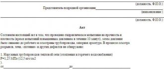
Drawing up a report based on the results of hydrotesting of the pipeline
After checking the pipeline system, a document is drawn up confirming that the tests were carried out in accordance with regulatory documentation and containing a report on the result of the check. The document displays:
- name of the pipeline network;
- name of the inspection company;
- data on pressure indicators during testing and the duration of its implementation;
- data on pressure reduction;
- a list of identified problems or an indication of their absence;
- date of inspection;
- conclusions of the commission.
Subtleties of crimping
For hydraulic testing, two methods are used:
- Manometric. The system is checked using measuring technology (independent pressure gauges). This allows you to record changes in pressure during testing and carry out calculations based on the measurements. The method is objectively more accurate.
- Hydrostatic. A more common method is testing communications without the use of pressure gauges. It becomes clear how the system behaves under non-standard loads, and its weak points are identified.
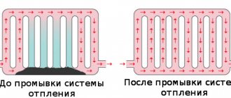
It is also important to understand that for effective operation, not only hydraulic testing of the water supply system is important, but also timely flushing of the system. When installing a pipeline, as well as during repair work, the system inevitably becomes clogged with small debris, which in the future will negatively affect the functionality of the circuit (especially the heating circuit).
The efficiency of coolant circulation is also reduced if air pockets have formed in the circuit. The fact that some of the air has not been forced out of the system is indicated by additional noise that occurs during the heating process; this may affect the heat transfer to the premises.
Pressure test of a heated floor system Source ytimg.com
Stands for hydrotesting
Test stands for pipeline fittings are research equipment, which includes: a frame, a hydraulic system, instrumentation, and additional devices. Bench testing allows you to determine several characteristics simultaneously with high accuracy. It is impossible to carry out such tests in the field and with such a level of accuracy.
Such stands are adapted for testing fittings for strength, tightness, and functionality of devices. These testing complexes are in demand for:
- incoming inspection of purchased fittings;
- intermediate and final control at production enterprises producing reinforcing elements;
- inspections after repair activities;
- periodic monitoring of the functionality of safety valves.
Tests for the strength and tightness of the valve body are carried out under static loading with increased pressure. The working medium of the hydraulic system is water or oil.
Briefly about the main thing
A comfortable life is unthinkable without the proper functioning of heating and water supply communications. To determine the readiness of the system for operation, hydraulic tests (pressure testing) are carried out.
During testing, increased pressure is created in the circuit. The amount of increase is calculated in advance based on the pipeline material and system parameters. There are two methods of crimping: precise (instrumental) using pressure gauges and hydrostatic, aimed directly at identifying defects (leaks or deformations).