If you decide to install a heated floor yourself, then you will inevitably be faced with the question of how to connect it correctly so that it is operational and heats the floor and the entire room. If you imagine this whole process, you can see that the key to the effectiveness of the system is the correct connection of the heated floor collector, which is responsible for regulating the temperature.
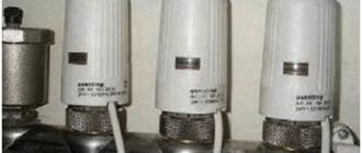
The collector looks like an ordinary piece of pipe with several holes on one side that serve as exits. A couple of such simple structures are actually responsible for controlling the water heated floor. Let's figure out why these outputs are needed and how to connect the underfloor heating manifold.
How does the collector work?
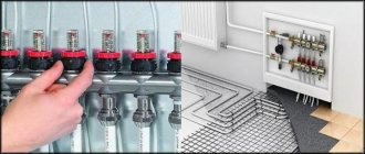
Water floors are laid in various ways, for example, concrete or flooring, but regardless of the technology chosen, it is necessary to purchase and install a manifold cabinet.
On a note
It is recommended to install the collector box on the wall as close to the middle as possible and most often near the floor.
In the future, two pipes will be inserted into it:
- supply, which leaves the boiler and supplies hot coolant to the system;
- return, which performs an absolutely opposite role: it serves to collect water that has already been used and has had time to cool. It is returned back to the boiler, and the process is repeated again.
The cyclical nature of the process is ensured by another built-in component of the system - a circulation pump. One way or another, during the operation of a heated floor, say during repair work, the system has to be turned off. To do this, each of the pipes is equipped with shut-off valves. A plastic pipe and a metal shut-off valve are connected to each other through a compression fitting. Then a comb is connected to the valve, mounting an air vent on one end and a drain valve on the other. After assembling the cabinet, they proceed directly to installation. And only with a comb already installed on the wall can you cut the circuit pipes to length.
On a note
To ensure the tightness of the connection, the pipes are cut strictly at a right angle.
Recommendations for choosing devices
Circulation pump for heating
When purchasing combs for heating, you need to consider several nuances:
- Models with collet clamps are susceptible to leaks at the valve connection areas. Their seal fails faster and cannot be replaced.
- The system functions normally only if there is a circulation pump.
- To hide the collector, you will need a special cabinet or niche.
- The maximum pressure indicator depends on the material of the block.
- The throughput of the distributor determines the amount of coolant moving through the pipes in a certain time.
- Auxiliary elements improve the functionality of the device.
- The number of outlet pipes must be equal to the number of cooling circuits.
Technical parameters are specified in the product passport.
Auxiliary elements
The collector heating system is organized using additional elements:
- air vent - installed when radiators and the unit are located on the same floor;
- adapter - needed when installing an air bleeder with a diameter of ½ inch on a manifold with a ¾ inch thread;
- corners - provide connection to the pipeline and direction of the air vent upward;
- faucet - needed to connect the pipe from the boiler to the distributor;
- a squeegee with a union nut - used to shut off the water or gas supply and disconnect a faulty device;
- clamps with plastic dowels or brackets - will be needed to fix the unit.
The collector connected to heated floors is equipped with a make-up tap.
Simplified diagram of a heated floor collector
The simplest comb circuit consists of two circuits. For the manufacture of the distribution system, brass or stainless steel is used - two materials with high resistance to the aggressive effects of hot water. The comb must be positioned strictly vertically on the wall to ensure the efficiency of all components and allow the coolant to be evenly distributed.
The shut-off valves installed in each circuit may have a manual or automatic opening system using electromechanical actuators. In the system we are considering, as a rule, manual ones are used.
With the help of these valves, one of which is installed at the inlet and the other at the outlet, the supply of hot water is controlled. To regulate the fluid flow between circuits located, say, in adjacent rooms, so-called balancing valves are installed in the return ridge.
Often the locking mechanism is supplemented with flow meters, which serve as an indicator of coolant flow. Thanks to them, it is possible to adjust each circuit of the system, since flow meters configure and measure the volume of coolant for each of them separately. This is especially important for circuits with different pipe lengths. Thermal sensors are installed on the return ridge, which are necessary to completely or partially shut off the system. This is done automatically using electric servos or manually.
As a rule, there are no problems when installing a simplified system yourself. When installing double-circuit heating, say, to heat a bathroom and toilet, there is no need for expensive equipment. Depending on which mixing valves are used, the ridge patterns become more complex.
Calculation of collector heating
The homeowner does not need to calculate the parameters of the collector (its flow diameter, length, cross-section of the outlet fittings) and the diameter of the pipes when purchasing a standard product. If you want to make such calculations, you can find the necessary formulas on the Internet, although in this case it is easier to focus on the standard dimensional parameters of manufactured factory products.
The main task of the calculations is to determine the length of the pipes to ensure the required temperature in the room with known temperature characteristics of the coolant. To do this, there is no need to resort to complex engineering calculations, which can only be carried out by narrow specialists in the field of heating; for the average person it is easier to use an online calculator or computer program.
To obtain the desired result, initial data about the required temperature in the room and its area, the diameter and pitch of the pipes, and the temperature of the medium are entered into the program or calculator. On the Internet you can find reviews of calculation programs Audytor CO from Sankom, Valtek Complex from the company of the same name, Raucad/Rauwin 7.0 from Rehau.
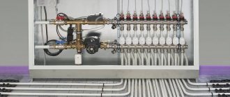
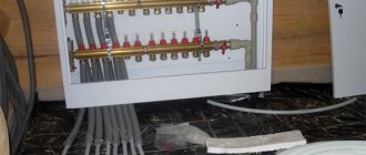
Rice. 17 Assembling the collector block
Mixing valves
When connecting the manifold, two types of mixing valves are used: two-way and three-way. They are designed for mixing liquids: hot, which comes from the boiler, and cooled, respectively, from the heating circuit. They are controlled manually or automatically - requiring additional installation of a servo drive or control device.
Three-way ones are used, as a rule, for collectors intended for heating large rooms with an area of more than 200 square meters. m. Such schemes also include weather-dependent sensors, which are programmed to determine the required floor temperature based on external conditions.
Two-way ones are used for rooms with a smaller area - less than 200 m2. In such a scheme, the floor temperature is controlled by a valve. If necessary, he himself adds hot liquid coming from the boiler or, conversely, water from processing. If the collector is configured correctly, overheating of the floor is completely eliminated. Two-way valve circuits provide smooth and stable adjustment.
There are many other collector schemes and installation types.
Control elements
Setting up a heated floor collector is impossible without special devices. With their help, the optimal heating mode of the system is established and water flows in the pipelines are regulated. Each of them performs a specific function.
- Water temperature sensor
Installed on the inlet and outlet pipes of the device. These devices do not affect the operation of the system, but indicate the current heating rate. The difference in values can be useful in calculating operating efficiency. They also serve as an indicator of heating mode violations.
- Central thermostat with servo mechanism and sensor.
It is mounted on the inlet pipe of the inlet manifold and connected to the return pipe with cooled coolant. The temperature sensor is placed in the comb body. There is a rotary knob on the body of the thermostat with which you can set the required temperature level. The device receives readings from the sensor about the degree of water heating. Depending on this, the flow of cold and hot coolant is regulated.
- Servo drives on the inlet comb nozzles
According to the principle of operation, they are completely similar to a thermostat, but with minor additions. With their help, the volume of water flow for each circuit of the water floor is regulated. Depending on the model, this can be done in manual or automatic modes. For the latter, servos with built-in temperature sensors are used, which can be connected to a common remote thermostat.
- Flow meters
Devices that are optional for installation, but which, however, can become effective elements for manually controlling the operation of a water heated floor. They are installed on the return manifold pipes and are locking mechanisms with a glass bulb.
When you turn the head on the body, the rod in the device changes its position. This affects the volume of liquid passing through it. For clarity, a measurement scale is printed on the surface of the flowmeter, indicating the flow rate of water l/min.
Connection rules
In most cases, a ready-made manifold is purchased, in which all elements are selected according to technical characteristics. If you have experience in assembling such structures, you can assemble the device yourself. How to properly connect a heated floor, take into account the parameters of the overall heating system and the technical properties of the combs? To do this, you must follow certain installation rules.
Attention
First, a general connection diagram is drawn up, which indicates the dimensions of the pipes, where they are laid and connections to the heating. The throughput capacity of each comb must be calculated, their diameter and material of manufacture must be selected. The most commonly used products are stainless steel or copper.
The location of the device is selected based on the following rules:
- The highways should be approximately equal in length.
- The section of the wall where the manifold cabinet for heated floors will be installed must have free access. Furniture or other parts of the interior do not interfere with a full inspection of the device or carrying out preventive or repair work.
- The connection point of the device must be higher than other elements of the system.
A security system must be installed. It consists of an air valve and a bypass. When the temperature of water rises sharply, it expands. The air valve releases excess air, normalizing the pressure in the pipes. A bypass is necessary to quickly shut off water in case of emergency situations.
Once the installation of the collector is complete, the underfloor heating pipelines are connected to it. The quality of the joints, their tightness and reliability must be checked. The system is started before the main covering is installed. By changing the temperature conditions using the control device, the heating quality of each line is checked, and the pipes are inspected for leaks. After this, you can begin installing the flooring.
Features of installation of the collector system
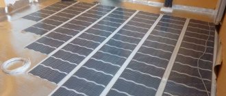
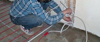
Installation of heating systems is carried out before finishing work on laying floor and wall coverings; the pipeline running along the floor is tied to a strong metal mesh and filled with a screed located on the insulation layer.
Apartment house
The implementation of collector heating in a residential apartment building is practically not used in everyday life, this is primarily due to the presence of radiator heating in buildings, in which all rooms in the apartment are heated by radiators. Laying circuits for heating rooms through floors is associated with significant financial costs and is ineffective; moreover, a comb is not required for laying a small number and short length of loops. A significant factor that makes the installation of collector heating in an apartment building useless is the imbalance and violation of the temperature regime of the entire house system, as a result of which penalties and dismantling of the installed heated floor are possible.
Cottage
Collector combs are the main elements in organizing heating of country houses and cottages; they are usually placed in the wall of rooms located in the center of the house on each floor, connected to a riser built into them.
To do this, during the construction stage, a recess is placed in the wall in which the comb is placed; to improve the aesthetic appearance, a manifold cabinet with closing doors is placed in the place of insertion.
One circuit is used for each room; if there are several radiators in the room, they are connected in series using a single-pipe passing or pass-through circuit (Leningrad). Several small circuits are installed if the area of the premises is large and the maximum length of the pipeline does not ensure its coverage at a given pitch.
Rice. 14 Combined heating system
Settings
As a rule, a special balancing table is attached to the diagram, on the basis of which the comb can be adjusted according to two parameters: circuit length and heating load.
The table relates the circuit number and the number of revolutions from the position of the balancing valve - “closed”. Set up the comb like this:
- remove the cap from the valve that serves to protect it;
- close the valve all the way - use a hex key for this;
- determine the number of revolutions for a given circuit;
- turn off the valve to this number;
- The remaining circuits are configured in the same way.
Correct configuration and connection of the collector are necessary for long-term operation and efficient operation of the system.
Exploitation
The layout of a heated floor collector is relatively simple. But during its operation, it is necessary to periodically check the performance of individual elements and the entire system as a whole. To do this, it is recommended to draw up a schedule for checking equipment and carrying out preventive maintenance of the following nature:
- Monitoring the performance of device elements.
- Checking the parameters of the coolant in each of the lines - speed, temperature. To do this, it is necessary to periodically take readings from control devices.
- Monitoring the integrity of the connection of pipelines to the combs, the absence of leaks and depressurization.
- Maintaining the temperature conditions of the system by taking data from thermometers.
By carrying out these simple procedures, you can maintain the uninterrupted operation of the entire system and its individual parts. But the main condition is the professional connection of the heated floor collector. The functionality of the device and its performance depend on the correctness of this installation stage.
© 2022 prestigpol.ru
What is a collector heating system
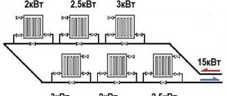
In heating, a collector is an element of water supply fittings designed to distribute through branches, collect and mix coolant from many parallel heat exchange circuits.
The collector circuit ensures the simultaneous supply of coolant to the circuits of underfloor heating and heating radiators (their maximum number in one comb reaches 12) with the same pressure and temperature, which can be set by a thermostat. The collector line differs from single-pipe and two-pipe systems in that it approaches the heating radiators from below.