In this article we will talk about the methods and rules for calculating ventilation in rooms. Ventilation systems are complex engineering networks. High-quality air exchange is the result of precise mathematical calculations , where there is no room for errors. What are the dangers of design violations? Insufficient or excessive air circulation. In the first case, this causes stagnation and stuffiness in the room. In the second - drafts, loss of heat and, as a result, colds. For industrial and commercial facilities, the consequences are much more serious: from regulatory fines to production shutdowns.
How to calculate ventilation coefficient
In rooms where people are the main source of changes in air condition, the minimum ventilation coefficient can be calculated using the following formula :
VN = n • Vj
- where VN is the supply air flow rate in m³/h;
- n is the number of people in the room;
- Vj — minimum inflow per person per hour, m³/h.
The minimum volume of supply air is specified in SNiP 13330.2012, 41-01-2003, 2.08.01-89 and depends on the characteristics of the room:
- ventilated room - 30 m³/h;
- room with air conditioning or ventilation with non-opening windows - 60 m³/h.
The organization of air exchange in a room comes down to the correct distribution of supply and exhaust elements in relation to the area where people stay and sources of pollution. The design of supply ducts has a decisive influence on the distribution and organization of air exchange, since their range is much greater than that of exhaust elements.
How to simplify the task - tips
You could see that calculations and organization of air exchange in a building are quite complex issues. We tried to explain the methodology in the most accessible form, but the calculations still look cumbersome for the average user. Let's give some recommendations for a simplified solution to the problem:
- The first 3 stages will have to be completed in any case - find out the volume of emitted air, develop a flow pattern and calculate the diameters of the exhaust air ducts.
- Take the flow velocity to be no more than 1 m/s and use it to determine the channel cross-section. It is not necessary to master aerodynamics - calculate the diameters correctly and simply bring the air ducts to a height of at least 3 meters above the intake grilles.
- Inside the building, try to use plastic pipes - thanks to their smooth walls, they practically do not resist the movement of gases.
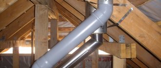
- Ventilation ducts laid in a cold attic must be insulated.
- Do not block the mine exits with fans, as is customary to do in apartment toilets. The impeller will not allow the natural hood to function normally.
To increase the flow, install adjustable wall valves in the rooms, get rid of all the cracks from where cold air can enter the house uncontrollably.
How to calculate supply and exhaust ventilation
In order for the ventilation system to work effectively, it is necessary to provide a sufficient amount of supply air, adapted to the type of room and the number of people in it. An inflow that is too small will not provide adequate air exchange, and one that is too high will lead to oversizing of the installation and additional costs. How to calculate supply and exhaust ventilation for a room? Below are the main methods.
Methods for calculating air exchange rates:
- By area: S×3 m³/h , where S is the size of the room for which the ventilation system is calculated, 3 m³/h is a constant value indicated in regulatory documents as recommended.
- According to sanitary standards: 60 m³/h×A + 20 m³/h×B, where A is the number of permanent residents, B is the number of temporarily present.
- By multiples: L=N×V , where N is the coefficient from the SNiP table, and V is the volume of the room.
The methodology for calculating ventilation is strictly regulated. The initial data is specified in SNiP, GOST and SP. Previously, we talked about what supply and exhaust ventilation is.
Location and dimensions of ventilation ducts
The minimum side size of the natural ventilation channel is 10 cm, and the minimum cross-sectional area is 0.016 m2, which approximately corresponds to the diameter of a standard ventilation channel pipe - 150 mm.
A channel of minimum size will provide air exhaust in a volume of 30 m3/hour with a vertical pipe length of more than 3 m. To increase the efficiency of the exhaust, increase the cross-sectional area of the channel or the length of the channel. Channels less than 2 m long do not provide the necessary intensity of natural ventilation.
In practice, the length of the ventilation duct on a floor is usually determined by design considerations - the number and height of the upper floors located above, the height of the attic, the length of the pipe above the roof. On the floor, the length of all channels must be the same.
This is done so that the traction force in each channel on the floor is approximately the same.
The cross-sectional dimensions of the channels on the floor are often made the same, but for design reasons - it’s more convenient. The performance of the ventilation channel in a particular room on the floor is adjusted by choosing the size of the ventilation grille.
Ventilation ducts from the premises of the house on different floors are placed side by side, combining them into a block of ventilation ducts.
For design reasons, they try to lay several ventilation ducts from rooms on the same floor side by side, in one place - to create a block of ventilation ducts.
| Examples of rational combination of exhaust ventilation ducts on the floor into one block (riser). |
A block of ventilation ducts in stone houses is usually placed inside the load-bearing internal wall of the house or attached to the wall.
The block is laid out from masonry materials, for example, brick. In brickwork, it is convenient to make channels with a cross-section that is a multiple of the size of the brick, taking into account the thickness of the joints - 140x140 mm
.
(1/2 x 1/2 brick, 196 cm2) or 140x270 mm
. (1/2 x 1 brick, 378 cm2)
Expanded clay concrete ventilation block, two-channel, 390x190x188 mm. The flow area of one channel is 168 cm2
Concrete blocks for laying ventilation ducts in a private house.
Block height 33 cm, width 25 cm, wall thickness 4 cm. The flow area of one channel is 12x17 cm (204 cm2) Hollow concrete blocks are produced, specially designed for laying ventilation ducts.
A block of ventilation ducts made of masonry materials must be supported on a foundation or on a reinforced concrete floor.
In other cases, for example, in wooden or frame houses, a block of ventilation ducts is assembled from plastic or galvanized steel pipes. The block of pipes is covered with a box.
How to combine several channels into one channel
In a private house, the number of channels is small, so there is no need to combine air flows from several channels (rooms or floors) into one, as is often done in apartment buildings. Each natural ventilation channel in a private house should begin in the room and end at the head on the roof. Any combination of two or more channels impairs ventilation performance.
In some cases, there is still a need to combine several channels, to combine them into one common natural ventilation channel.
Read:
How to combine several channels into one common ventilation channel
Ventilation channel performance
Performance of a single exhaust ventilation duct with a cross-section of 12x17 cm (204 cm2) made of concrete blocks, depending on the height of the duct and the room temperature:
Capacity of natural ventilation channels with a cross section of 12 x 17 cm (204 cm2) depending on the height of the channel and the room temperature (at an outside air temperature of 12 ° C)
To determine performance for intermediate channel heights, plot the channel height versus performance graph.
Similar tables can be found for ventilation ducts that are made of other materials.
However, for ventilation ducts of the same cross-section (204 cm2), but made of other materials, the performance will differ slightly from that indicated in the table.
For a channel of a different cross-section, the performance value from the table can be proportionally increased or decreased.
Household products
⇆
To increase the performance of a ventilation channel of the same height, it is necessary to proportionally
increase the cross-sectional area of the channel. To do this, for example, choose a concrete block with a larger hole, or use two or three channels of the above size to ventilate one room.
How to calculate exhaust ventilation in production
An effective industrial ventilation unit effectively removes contaminated air from the point of emission, limiting its spread in the hall as much as possible, and at the same time provides the supply of purified and treated air for the needs of employees. It is necessary to think through and plan the operation of local exhaust, general exchange and supply ventilation units. Calculation of the required air flow of extracted and supplied air is the beginning of work on the ventilation project for production workshops. The key issue is the correct location of air intakes and outlets in the room and the choice of equipment (fans, air handling units, ventilation devices, pipes, dust collectors, filters).
Ventilation design must meet the requirements set out in the relevant codes and standards. Accurate knowledge of the technological processes of distribution of pollution sources, their type, quantity and method of distribution is necessary. Each production plant project is unique and requires individual analysis. Employees of the QWENT engineering company will professionally install industrial ventilation in production.
Local exhaust
If harmful substances are emitted during production processes at one of the sites, then, according to the standards, a local exhaust hood must be installed near the source. This will make the removal more effective.
Most often, such a source is technological tanks. For such objects, special installations are used - suction units in the form of umbrellas. Its dimensions and power are calculated using the following parameters:
- dimensions of the source depending on the shape: length of sides (a*b) or diameter (d);
- flow velocity in the source area (vв);
- installation suction speed (vз);
- the height of the suction above the tank (z).
The sides of a rectangular suction are calculated by the formula: A = a +0.8z, where A is the suction side, a is the reservoir side, z is the distance between the source and the device.
The sides of a round device are calculated by the formula: D=d +0.8z, where D is the diameter of the device, d is the diameter of the source, z is the distance between the suction and the reservoir.
The hood is predominantly shaped like a cone, the angle of which should not exceed 60 degrees. If the mass velocity in the workshop is more than 0.4 m/sec, then the device should be equipped with an apron. The amount of exhaust air is set by the formula: L=3600vз*Sa, where L is the air flow in m3/hour, vз is the flow rate in the exhaust, Sa is the working area of the suction. Expert opinion
How to calculate ventilation in a house
The performance of the ventilation network in a private home is calculated in two ways.
- The first is in terms of room volume and circulation rates.
- The second is based on the number of people constantly present in the building and the air flow rate per person.
For residential premises, the norm is a single air exchange. To calculate it using the first method, you need to multiply the volume of the room by the replacement rate of air masses.
The air flow rate for a person who is constantly in the room is 60 m3/h, and if a person is in it temporarily - 20 m3/h. This data will be needed for the second method. The number of people in the room must be multiplied by the air flow rate.
The air exchange rate is a number that shows how many times per hour the air in the room is completely replaced with fresh air. The multiplicity is regulated by standards and depends on the room. It is determined using tables.
For a private house, you can take the average value between the results calculated using these two methods.
Stages
The selection of the optimal air exchange system in terms of power and cost is carried out step by step. The design order is very important, since the efficiency of the final product depends on its observance:
- Determination of the type of ventilation system. The designer analyzes the source data. If you need to ventilate a small living space, then the choice falls on a supply and exhaust system with natural impulse. This will be enough when the air flow is small and there are no harmful impurities. If you need to calculate a large ventilation complex for a factory or public building, then preference is given to mechanical ventilation with the function of heating/cooling the inlet, and if necessary, then with calculations based on hazards.
- Outlier analysis. This includes: thermal energy from lighting fixtures and machines; fumes from machines; emissions (gases, chemicals, heavy metals).
- Calculation of air exchange. The task of ventilation systems is to remove excess heat, moisture, and impurities from the room with an equilibrium or slightly different supply of fresh air. To do this, the air exchange rate is determined, according to which the equipment is selected.
- Equipment selection. Produced according to the obtained parameters: required volume of air for supply/exhaust; indoor temperature and humidity; the presence of harmful emissions, ventilation units or ready-made multi-complexes are selected. The most important parameter is the volume of air required to maintain the design expansion ratio. Filters, heaters, recuperators, air conditioners and hydraulic pumps are used as additional network devices that ensure air quality.
How to calculate natural ventilation in a room
Natural ventilation works without mechanical stimulation. Air changeability is ensured by gravity - the temperature difference between incoming and exhaust air. For normal operation, it is necessary to calculate the height of the vertical exhaust shaft. Calculations are carried out using the selection method, because vertical shafts in most cases have a standard size and height. The height of the shaft is substituted into the calculation of natural ventilation, carried out according to the formula: p=h(pH-pB) , where p is the gravitational pressure in the channel, h is the height of the air duct, pH is the density of incoming air masses, pB is the density of exhaust air.
Gravity ventilation involves designing places for air supply to the premises of a building and places for exhaust air removal. In this case, air enters the room through window and sill openings, leaky connections and as a result of periodic opening of windows and doors. The disadvantage of natural ventilation is its dependence on the outside air temperature. The efficiency of exchange decreases with increasing outdoor temperature. The higher the outside air temperature, the smaller the pressure difference causing air flow, so with constant resistance to flow, air exchange worsens. However, in winter, cold air enters the premises uncontrollably, which requires additional thermoregulation.
Selecting the height of the pipes
The next step is to determine the traction force that occurs inside the exhaust unit at a given height difference. The parameter is called available gravitational pressure and is expressed in Pascals (Pa). Calculation formula:
- p – gravitational pressure in the channel, Pa;
- H – height difference between the outlet of the ventilation grille and the cut of the ventilation duct above the roof, m;
- ρair – room air density, take 1.2 kg/m³ at home temperature +20 °C.
The calculation method is based on selecting the required height. First, decide how much you are willing to raise the exhaust pipes above the roof without damaging the appearance of the building, then substitute the height value into the formula.
Example. We take a height difference of 4 m and get the thrust pressure p = 9.81 x 4 (1.27 - 1.2) = 2.75 Pa.
Now comes the most difficult stage - the aerodynamic calculation of the outlet channels. The task is to find out the resistance of the air duct to the flow of gases and compare the result with the available pressure (2.75 Pa). If the pressure loss is greater, the pipe will have to be expanded or the bore diameter increased.
The aerodynamic resistance of the air duct is calculated by the formula:
- Δp – total pressure loss in the shaft;
- R – specific frictional resistance of the passing flow, Pa/m;
- H – channel height, m;
- ∑ξ – sum of local resistance coefficients;
- Pv – dynamic pressure, Pa.
Let us show with an example how the resistance value is calculated:
- We find the value of dynamic pressure using the formula Pv = 1.2 x 1² / 2 = 0.6 Pa.
- We find the friction resistance R from the table, focusing on the dynamic pressure of 0.6 Pa, flow velocity of 1 m/s and air duct diameter of 225 mm. R = 0.078 Pa/m (indicated by a green circle).
- The local resistances of the exhaust shaft are a louvered grille, a 90° upward outlet and an umbrella at the end of the pipe. The coefficients ξ of these parts are constant values, equal to 1.2, 0.4 and 1.3, respectively. Sum ξ = 1.2 + 0.4 + 1.3 = 2.9.
- Final calculation: Δp = 0.078 Pa/m x 4 m + 2.9 x 0.6 Pa = 2.05 Pa.
Let's compare the calculated pressure generated in the air duct and the resulting resistance. The traction force p = 2.75 Pa is greater than the pressure loss (resistance) Δp = 2.05 Pa, a 4-meter-high shaft is too high, it makes no sense to build one.
Now let’s shorten the ventilation duct to 3 m and recalculate again:
- Available pressure p = 9.81 x 3 (1.27 - 1.2) = 2.06 Pa.
- The resistivity R and local coefficients ξ remain the same.
- Δp = 0.078 Pa/m x 3 m + 2.9 x 0.6 Pa = 1.97 Pa.
The natural draft pressure of 2.06 Pa exceeds the system resistance Δp = 1.97 Pa, which means that a three-meter-high shaft will work properly for natural exhaust and will provide the required flow of removed gases.
Important note. The difference between the traction force and the resistance of the air duct was only 2.06 - 1.97 = 0.09 Pa. In order for the hood to work stably in any weather, it is better to take the height of the pipe in our example with a margin of 3.5 m.
The ventilation channel Ø225 mm can be divided into 2 smaller pipes, but not by diameter, but by cross-section. We get 2 round ventilation ducts 150-160 mm, as shown in the photo. The height of both shafts remains unchanged - 3.5 m.
How to calculate ventilation in an apartment
- Children's room, bedroom, living room - air exchange once per hour.
- Kitchen with electric stove - 60 m³/h.
- Kitchen with gas stove - air exchange once per hour + 100 m³/h when the stove is running.
- Bathroom - 25 m³/h.
- Library, recreation area - 0.5 times per hour.
- Wardrobe, hallway, utility room - 0.2 times per hour.
The calculation of ventilation in a residential area is carried out on the basis of SNiP 13330.2012, 41-01-2003, 2.08.01-89. Most often, two methods are used: by volume of air flow per hour or hourly frequency. The standards depend on the type of premises listed above.
Bottom line
Knowing the air balance of a residential building, the size of the cross-section of the air ducts is selected. Most often, rectangular channels with an aspect ratio of 3:1 or round are used.
Home ventilation plan Source sustaintrust.org.nz
To conveniently calculate the cross-section, you can use an online calculator or a diagram that takes into account the speed and air flow.
For natural ventilation, the speed in the main and branch air ducts is assumed to be 1 m/h. In the forced system, 5 and 3 m/h, respectively.
With a required air exchange of 200 m3/h, it is sufficient to implement a natural ventilation system. For large volumes of transported air, mixed recirculation is used. Devices designed for performance are installed in the channels, which will provide the necessary microclimate parameters.
How to calculate forced ventilation
Forced ventilation works on a mechanical principle. Electric fans are responsible for air movement and circulation. There are 3 types of mechanical ventilation. The supply air supply brings air into the room, and the exhaust air supply removes it. The supply and exhaust system works for supply and outflow at the same time. It can be equipped with a recuperator - a heat exchanger that absorbs the heat of the exhaust air and warms the supply air.
When making calculations and designing, the following are taken into account:
- volume of inflow and outflow;
- dimensions of the mines;
- air duct parameters;
- power of electric fans;
- heat loss during the heating period;
- heat exchanger characteristics;
- resource of filtration systems;
- parameters of duct heaters and coolers;
- consumed electricity;
- sound insulation thickness.
independently calculate mechanical ventilation . It's better to leave this to an engineer.
Calculations
Calculation of living rooms
Sum of areas: 12 + 16 + 21 = 59 m2. Air volume for exchange according to SNiP: 59 x 3 = 177 m3.
Calculation for a bathroom or kitchen
The requirement for the hood is to ensure complete air exchange within 15 minutes. The standard volume of the kitchen is: 9 x 7 = 27 m3, which must be removed in a quarter of an hour. Accordingly, the throughput of the hood fan will be no less than 27 x 4 = 108 m3/hour during operation of the hood (40–60 min/day).
In practice, this figure for most household hoods is much higher - from 220 m3/hour, but in 50% of cases they run idle due to the lack of inflow.
Calculation of bathroom premises
Bathroom. Air volume: 4 x 3 = 12 m3/hour. Complete air exchange in 5 minutes (1/12 hour). Throughput - 12 x 12 = 144 m3/hour.
Toilet. Air volume: 2 x 3 = 6 m3/hour. Complete exchange in 5 minutes (1/12 hour). The system capacity is 6 x 12 = 72 m3/hour.
Let us recall that the calculated indicators relate to the inflow throughput, on the basis of which exhaust equipment is selected.
The obtained data can be combined into a table:
| Room | Area, m2 | Exchange according to SNiP norm, m3/hour | Optimal channel diameter, mm | Number of elbows, pcs. | Inflow source | Note |
| Bedroom | 16 | 16 x 3 = 48 | 125 | 1 | Window/wall valve | Periodic ventilation 10 hours a day (from 22.00 to 08.00) |
| Children's | 12 | 12 x 3 = 36 | 100 | 2 | Constant ventilation | |
| Living room | 21 | 21 x 3 = 63 | 125 | 2 | Constant ventilation | |
| Kitchen | 9 | 90 (108 at peak) | 150 | 3 | Window/wall valve through living areas | Constant ventilation with periodic intensification (exhaust) |
| Bathroom | 4 | 25 (144 at peak) | 150 | 2 | Periodic increased ventilation | |
| Toilet | 2 | 30 (72 at peak) | 150 | — | Periodic increased ventilation |
Question. How to ensure an inflow of 144 m3/hour into the bathroom if the maximum capacity of the supply valves is 40 m3/hour?
Answer. Connect the inlet for the bath and toilet to the combined exhaust from the living rooms. The air quality is quite suitable for enhanced ventilation, and a total of 120 m3/hour of inflow will ensure normal efficiency of the hood.
The number of elbows is an indicator of the power loss of the exhaust fan (2% per one elbow), take this into account when selecting equipment.
Based on the data provided, you can select equipment - window and wall valves, fans and hoods, ducts. The main thing is to follow the rule - the volume of inflow must be equal to the volume of air exhaust. It is advisable to use a centralized multi-channel system with outlets to each room (300–700 USD), and install power controllers and switch-on timers in individual rooms (from 15 USD/piece).
Using the adapted methodology given in the article, you can save on the services of professionals. This is quite acceptable, given the low complexity. Now all that remains is to choose equipment, the price of which will depend only on the quality of the product and the noise level.
We are a professional engineering design and installation company. On our website you can receive a commercial offer and find the necessary information.
How to calculate and select equipment for supply and exhaust ventilation of an apartment from EuroHolod (Moscow). Receive a commercial offer by calling.
To receive a commercial offer
, write a request to e-mail [email protected] or send a quick request
See below
- Ventilation systems
- Supply and exhaust ventilation
- Installation of supply and exhaust ventilation system
- Design of supply and exhaust ventilation system
- Maintenance of air handling units
- Collapsible/assembled (modular) and monoblock supply and exhaust ventilation systems
How to calculate air ducts for ventilation
To calculate the cross-sectional area of air ducts, you need to know the volume of air entering the room per unit time and the speed of movement of air masses in the ventilation duct. After calculating the volume, the parameters of the exhaust ducts are calculated. To find out the cross-sectional area, use the formula: F = L/3600 x Vс , where L is the specific flow rate of exhaust ventilation, m³/h; Vc – speed of air movement in the line, m/s. Previously, we talked in detail about air ducts for ventilation.
Calculate the diameters of ventilation ducts
Further calculations are somewhat more complicated, so we will provide each step with examples of calculations. The result will be the diameter and height of the ventilation shafts of our one-story building.
We distributed the entire volume of exhaust air into 3 channels: 100 cubic meters. The hood in the kitchen is forcibly removed when the stove is turned on, the remaining 271 cubic meters goes through two identical shafts naturally. The flow rate through 1 air duct will be 271 / 2 = 135.5 m³/h. The cross-sectional area of the pipe is determined by the formula:
- F – cross-sectional area of the ventilation duct, m²;
- L – exhaust flow through the shaft, m³/h;
- ʋ—flow speed, m/s.
Reference. The air speed in the natural ventilation channels is in the range of 0.5–1.5 m/s. We take the average value as the calculated value - 1 m/s.
How to calculate the cross-section and diameter of one pipe in the example:
- We find the diameter size in square meters F = 135.5 / 3600 x 1 = 0.0378 m².
- From the school formula for the area of a circle, we determine the diameter of the duct D = 0.22 m. We select the nearest larger air duct from the standard range - Ø225 mm.
- If we are talking about a brick shaft embedded inside the wall, then the size of the ventilation duct 140 x 270 mm will fit the found cross-section (good coincidence, F = 0.0378 sq. m.).
Brick shafts have strictly fixed dimensions - 14 x 14 and 27 x 14 cm.
The diameter of the outlet pipe for a household hood is calculated in the same way, only the flow speed forced by the fan is assumed to be greater - 3 m/s. F = 100 / 3600 x 3 = 0.009 m² or Ø110 mm.
How to calculate the cost of ventilation
The total cost of a ventilation system consists of several elements. The most important of them are:
- project cost;
- equipment and installation costs;
- operating costs (control panel energy consumption, filter replacement, maintenance).
The price of equipment depends on the quality of workmanship, power, technical parameters, additional functions (for example, cooling or humidifying the air in the house), convenient control (degree of automation). The complexity of installation also increases the cost. Our website contains the most detailed price list for designing a ventilation system with prices per m².
Conclusions and useful video on the topic
Video #1. Useful information on the principles of operation of the ventilation system:
Video #2. Along with the exhaust air, heat also leaves the home. Calculations of heat losses associated with the operation of the ventilation system are clearly demonstrated here:
Correct calculation of ventilation is the basis for its successful functioning and the key to a favorable microclimate in a house or apartment . Knowledge of the basic parameters on which such calculations are based will allow not only to correctly design the ventilation system during construction, but also to adjust its condition if circumstances change.
Would you like to share your own experience in the calculation and construction of ventilation? Did you have any questions while reviewing the information? Found any flaws in the text? Please write comments in the block located under the text of the article.
Calculation according to sanitary and hygienic standards
Air exchange in the room is regulated by SNiP, according to which the ventilation system must ensure:
- Supplying outdoor air to living rooms such as living room, bedrooms, offices, children's rooms and kitchen with an external window.
- Removing exhaust air from the kitchen, bathroom, toilet, corridor, rooms without windows. These include: dressing room, pantry, utility room.
The calculation of the amount of ventilated air is based on the balance of heat, moisture and pollutant emissions, that is, factors causing changes in air parameters in the room. The amount of supply air can be calculated based on:
- heat load of the room (heat gain);
- steam gain;
- the amount of gaseous pollutants emitted into the premises;
- number of people.
The choice of method of supplying air to a room requires careful analysis from the point of view of ensuring adequate comfort for the users in it. Determining the cooling capacity of the air flow and comparing it with acceptable values is a prerequisite for correct air distribution. The method of supplying air to the room determines the permissible inlet temperature, which determines the amount of air flow, the size of air ducts and other ventilation devices.
Types of ventilation systems according to the method of creating draft
The movement of air masses occurs as a result of pressure differences between layers of air. The greater the gradient, the stronger the driving force. To create it, a natural, forced or combined ventilation system is used, which uses supply, exhaust or recirculation (mixed) methods of air removal. Emergency and smoke ventilation are provided in industrial and public buildings.
Natural ventilation
Natural ventilation of rooms occurs according to physical laws - due to the difference in temperature and pressure between the external and internal air. Even during the times of the Roman Empire, engineers installed the likes of shafts in the houses of the nobility, which served for ventilation.
The natural ventilation complex includes external and internal openings, transoms, vents, wall and window valves, exhaust shafts, ventilation ducts, and deflectors.
Natural ventilation Source rumahku.com
The quality of ventilation depends on the volume of passing air masses and the trajectory of their movement. The most favorable option is when the windows and doors are located at opposite ends of the room. In this case, when air circulates, it is completely replaced throughout the room.
Exhaust ducts are placed in rooms with the highest levels of pollution, unpleasant odors and humidity - kitchens, bathrooms. Supply air comes from other rooms and pushes exhaust air out into the street.
In order for the hood to work in the desired mode, its top must be 0.5-1 m above the roof of the house. This creates the necessary pressure difference to move air.
Natural ventilation is silent, does not consume electricity, and does not require large investments in the device. Air masses penetrating from outside do not acquire additional properties - they are not heated, not purified or moistened.
Air recirculation is limited to one apartment. There should be no suction from neighboring rooms.
Forced ventilation
Forced ventilation began to be used from the mid-19th century. At first, large fans were used in mines, in the holds of ships, and in drying shops. With the advent of electric motors, a revolution occurred in room ventilation. Adjustable devices have appeared not only for industrial, but also for domestic needs.
Forced ventilation Source stroy-podskazka.ru
Calculation of the ventilation system by multiplicity
Multiplicity standards suggest taking into account the type of room. The multiplicity shows how many times all the air in the room should be changed in an hour. When determining the air exchange rate for each specific room, designers take into account the regulatory indicators recorded in sanitary and hygienic standards, GOSTs and building rules, for example SNiP 2.08.01-89.
The amount of air can be calculated using the formula L=N*V , where N is the air exchange rate per hour, taken from the table; V – volume of the room, cubic meters. m.
Rules for calculating hood power taking into account the kitchen area
To calculate the power and performance of a kitchen hood, you need to take its height and area as a basis. Cheap models have a capacity of up to 300 m3. They are installed in small spaces and in conditions of infrequent cooking. If the stove is used frequently, it is advisable to select an exhaust device with a capacity of at least 600 m3/h.
The exhaust apparatus should provide 6-fold filtration in the first mode, 9-fold in the second, and in the third – 12-fold filtration of the entire volume of contaminated air within an hour.
You can calculate productivity using the example of a studio kitchen with an area of 75 m3:
Mode 1 – 6 air changes per hour, i.e. 6 × 75 = 450 m3/h;
Mode 2 – 9-fold filtration of the entire volume per hour, i.e. 9 × 75 = 675 m3/h;
Mode 3 – 12-fold circulation of air masses, i.e. 12 × 75 = 900 m3/h.
Usually the device operates in the first or second mode, so you need to pay attention to the technical characteristics of the exhaust device to find out whether its parameters correspond to the kitchen area.
Devices with a capacity of 1000 m3/hour purify the air most effectively. They are installed if the kitchen is combined with another room and the area exceeds 40 square meters. An exhaust device will clean the air, but it will take longer. After cooking, it is necessary that it work for at least 10 minutes to remove all odors and burning.
Heater power
A heater or duct heater is a universal device for heating supply air, installed in ventilation ducts. Heater power (Q) is calculated by the formula: Q = V • ρ • cp • ΔT [kW] , where V is the volumetric air flow [m³/s], ρ is the air density [1.2 kg/m³], cp is the specific heat capacity of air [1.005 kJ/(kg • K); ΔT is the difference in air temperatures before and after the heater [°C]. Manufacturers of air heaters also provide nomograms, according to which equipment can be selected much faster. It is enough to know the volume of the room, the difference between the supply air temperature and the heating temperature. Previously, we talked about what a heater in ventilation is.
Design errors
At the project creation stage, errors and shortcomings are often encountered. This may be excessive background noise, reverse or insufficient draft, blowing (upper floors of multi-storey residential buildings) and other problems. Some of them can be solved after installation is completed, using additional installations.
A striking example of low-skilled calculation is insufficient exhaust draft from a production facility without particularly harmful emissions. Let's say the ventilation duct ends in a round shaft, rising 2,000 - 2,500 mm above the roof. Raising it higher is not always possible or advisable, and in such cases the principle of flare emission is used. A tip with a smaller diameter of the working hole is installed in the upper part of the round ventilation shaft. An artificial narrowing of the cross-section is created, which affects the rate of gas release into the atmosphere - it increases many times over.
Sample Project
The method for calculating ventilation allows you to obtain a high-quality internal environment by correctly assessing the negative factors that worsen it. We employ professional designers of engineering systems of any complexity. We provide services in Moscow and neighboring regions. The company also successfully engages in remote collaboration. All communication methods are listed on the “Contacts” page, please contact us.
Ventilation calculation example
- reception: 2*60 = 120 m³/h;
- workroom No. 1: 4*60+2*20 = 280 m³/h;
- No. 2: 6*60+2*20 = 400 m³/h;
- No. 3: 8*60+2*20 = 520 m³/h.
Above is an example of calculating the inflow volume.
For clarity, we will calculate the parameters of the ventilation network of a classic medium-sized office. Input data: reception (two workplaces), 3 offices (4, 6 and 8 workplaces + two places for visitors in each). Each employee's workplace requires 60 m³ of fresh air per hour. Additional - 20 m³/h.
The total supply air flow will be 120+280+400+520 = 1320 m³/h.
Proper duct equipment
Galvanized boxes can be round, square and rectangular in shape. Pipes are often installed to organize the supply flow in industrial and public premises. For installation, clamps are used that are attached to the ceiling with studs. Rectangular boxes are suspended on rigid traverses, where the height is adjusted with a control nut. Rubber gaskets are required.
Flexible air ducts up to 5 m long are laid without intermediate supports, longer pipelines are fixed with hangers and clamps on studs to avoid deflection. Despite the flexibility, such highways have certain radii beyond which it is not recommended to turn the route.