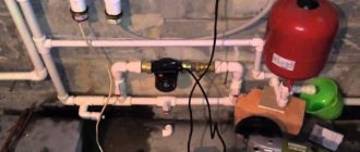
There are frequent cases of a gas boiler taking too long to ignite, which is due to automation. Gas boilers, both Russian and foreign, are equipped with EUROSIT 630 valves, which serve as a set temperature controller and alarm in the event of an emergency. The valve automatically shuts off the gas supply to the burners. But then you can turn it on only manually. But this is not the only reason for the emergency.
Let us consider, as an example, boilers that have automatic protection against loss of fire on the igniter and disturbance of draft.
All work associated with the danger of a gas explosion must be carried out by specialists from enterprises with the appropriate permit. You can only monitor the progress of the work.
So, EUROSIT 630 has three modes - shutdown, ignition and temperature controller.
- To ignite the igniter, you need to move the control knob to the primary position, then press it using a button with a piezoelectric element. In this way, a dense burner is ignited. By the way, you need to hold the handle for 5 seconds. When the igniter lights up, it should continue to support the combustion process; if it goes out, repeat the ignition procedure. If, after several attempts, the combustion still stops, you should begin searching for the cause of the malfunction.
The fact is that the igniter is ignited, the flame must warm up the thermocouple, which will lead to the formation of an EMF, which will be sufficient to reach the sensor circuit, and then the solenoid valve.
- If you press the gas valve handles, the EM valve will open, causing gas to flow to the igniter. With the correct and proper functioning of the equipment, the EMF thermocouple will be able to hold the gas, and the valve will remain open. The thermocouple acts, in a sense, as a fuse against gas loss. Optimally closed indicators are built into the circuit, which are sure to work, thus opening the contacts, and also, in case of problems, turning off the boiler.
Chemical compositions
How to flush the heat exchanger of a gas boiler?
The safest option is citric acid. Industrial products for washing the heat exchanger of a gas boiler - Cillit, DETEX, Sanax. Hydrochloric acid is more effective. But its use is more dangerous for both the user and the system. Concentrated acid can destroy the internal protective layer of the heat exchanger and also increase the fragility of the metal.
External treatment of contaminated parts is carried out with special compounds to remove soot and carbon deposits. As a last resort, you can use household detergents.
Video about flushing the heat exchanger of a gas boiler.
Periodic flushing of the gas boiler heat exchanger is a basic requirement for the maintenance of heating equipment. Cleaning significantly affects the smooth operation of the entire system and greatly extends the life of the home heating device. When do you need to do flushing and can you do it yourself?
When a gas boiler operates, a layer of scale forms, which prevents the necessary cooling of the heat exchanger. In this case, the circulation pump takes on a greater load. Therefore, without flushing the heat exchange device, the heating unit may fail.
At home, cleaning should be done every two years. If the water in your home is quite hard, it is recommended to reduce the interval between flushes.
The first signs for the user of the need to flush the heat exchanger are:
- long-term heating of a gas boiler;
- reduction in thermal output;
- partial heating of the system;
- presence of extraneous sounds during operation of the heating device;
- significant increase in gas consumption.
When scale appears in double-circuit boilers, the water may not fully warm up or the pressure level may decrease.
It is advisable to avoid a combination of such symptoms. But if alarming signs appear, flushing should be done immediately.
In addition to internal cleaning of the heat exchanger, external cleaning of its body from soot is used. Socialized services are responsible for eliminating scale and contamination in the gas boiler system. The cost of their services is not cheap. Therefore, sometimes you can wash the heat exchanger yourself.
In what cases is it necessary to adjust the burner flame?
An atmospheric gas burner for heating equipment often fails. It is equipped with models of both wall-mounted and floor-standing boilers. The injection burner of floor-standing equipment reduces its efficiency for various reasons:
- Burner power is too high. This happens when a high-power burner is purchased for small heating equipment. At the same time, there is not enough space for combustion, the air flow for such power is weak, which leads to the transition of the flame from blue to yellow, sooting of the combustion chamber and chimney.
- If the chimney is poorly cleaned, the boiler draft deteriorates. At the same time, waste combustion products are poorly removed, and the air flow is small. This worsens combustion and the flame turns yellow.
- A defect in the burner itself does not make it possible to correctly adjust the complete combustion of the fuel.
- Due to pressure changes in the gas supply system, well-regulated equipment can release large amounts of unexhausted gas into the chimney. Partially it settles with soot and soot. A large layer of soot reduces traction and increases fuel consumption.
- Starting heating equipment after repair.
- The presence of extraneous noise during operation of the boiler or gas burner.
- Changing the type of fuel.
You may be interested in learning about the operating principle of a double-circuit gas boiler >>>
Operating a gas boiler
Necessary tools: multimeter, pliers, flat-head screwdriver, alcohol, open-end wrenches - 9, 10, 12. Troubleshooting involves, first of all, inspecting the thermocouple and solenoid valve. Having previously found the draft sensor on the gas duct, it is necessary to remove the two terminals and connect them tightly with pliers to close each other, while simultaneously attempting to ignite.
If the ignition problem still remains, then the cause of the problem is probably in the traction sensor, which needs to be checked in this way - tight fixation of the contacts, integrity of the paronite gaskets, the presence of a gap between the hole in the gas pipeline and the plane of the sensor. It is necessary to examine the rating of the sensor; if there is a temperature discrepancy, it will not open. Oxidation on the contacts, even unnoticed, is not allowed. Then the traction sensor is checked for the degree of resistance using a tester. The sensor must be replaced if the resistance is deviating, that is, not minimal. You should find an identical, working sensor with similar temperature performance.
If no failures are detected with the sensor, then it’s time to wipe the contacts and terminals of the circuit using alcohol, then dry and tighten them. Then the traction sensor returns to its place and the ignition attempt is repeated again.
It is necessary to monitor the burner draft after each attempt to ignite, placing your palm on the sensor and noting the lack of heat flow. The problem must be corrected if there is a flow.
Igniter in a gas boiler
The next possible cause of failure could be the combination of the traction breaker and the sensor contacts. The manipulations with the terminals and resistance measurements are repeated again, the norm of which is up to 3 Ohms. Next, take the open-end wrench “9” and unscrew the nut that secures the thermocouple to the traction breaker. This breaker includes 2 components - a brass sleeve and a plastic insert, the removal of which allows you to completely unscrew the part.
If ignition is unsuccessful in the igniter, the problem may lie in the thermocouple, due to the fact that malfunctions of the solenoid valve rarely occur. Next, for diagnostic purposes, the thermocouple is connected to the solenoid valve and secured with a key. The thermocouple is not hopeless and can be corrected; for example, it is possible to solder a disconnected contact instead of irrationally replacing the part.
Do not forget to inspect the dielectric gasket and return the thermocouple to its place, paying attention to the location of the tip. Let us remind you that cleaning procedures are carried out with an alcohol-containing liquid and high-quality drying is carried out before assembly.
From this article you will learn what problems can arise in the automation of gas boilers, why it is impossible to ignite the igniter, which is why the boiler can turn off for no reason, and most importantly, we will figure out what actions need to be taken to diagnose and eliminate this malfunction.
Owners of non-volatile gas boilers are probably familiar with the situation when, for some reason, it is not possible to ignite the boiler, or a lot of time is spent on ignition. In this case, the problem lies in the boiler automation.
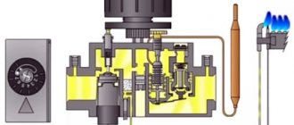
Today, the gas valve EUROSIT 630 is most often used in domestic and imported gas equipment. It is this valve that performs the function of maintaining the set coolant temperature and, in the event of an emergency, completely shuts off the gas supply to the burners. Further starting of boilers with such automation is only possible manually. However, the cause of a boiler emergency shutdown is not always a real accident.
Let's try to understand this using the example of the Zhitomir-3 boiler. Automatically, it provides protection against loss of flame on the igniter and loss of traction.
Note:
All gas-hazardous work must be carried out exclusively by representatives of specialized organizations that have the appropriate permits. Therefore, this article is provided for informational purposes only. This article will also help you monitor the work of the technician and, perhaps, save you from the need to purchase unnecessary spare parts.
Let's decide what we will call igniting the igniter. The EUROSIT 630 valve control knob allows you to switch the boiler to three main modes:
- disabled;
- ignition;
- temperature adjustment (1–7).
To ignite the pilot burner (igniter), you must move the control knob to the “ignition” (spark) position, press it and use the piezo ignition button to ignite the pilot burner. Next, the handle is held for several seconds (no more than 30) and released. The pilot light should continue to burn. This is what we will call igniting the igniter. If the pilot light goes out, you need to repeat the procedure several more times. If this does not help, you need to look for the problem.
At the moment the igniter is ignited, the flame heats the thermocouple, which in turn generates an EMF (approximately 25 mV for working SIT thermocouples), which is supplied through the automation sensor(s) circuit to the solenoid valve.
By pressing the gas valve handle, we manually open the solenoid valve, supplying gas to the igniter, which, if the equipment is operating correctly, is held by the EMF generated by the thermocouple and remains in the open position after the handle is released. The thermocouple itself performs the function of protecting against loss of flame on the igniter. The sensors located in the circuit are normally closed and, when triggered, open their contacts, ensuring complete shutdown of the boiler.
Automation SABK-M, a piezomechanical device proven over the years for monitoring the operation of boilers!
Good afternoon
Today we will raise such an interesting topic for many RuNet users as spare parts for automatic gas devices of the SABK-M, SABK-SRD, SABK-T and other popular models. We stay in touch at any time! The Installer company works for you! We stay in touch at any time! The Installer company works for you!
Structure, principle of operation, instructions
Any automation kit consists of the following essential parts:
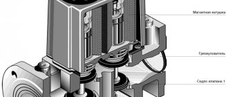
The operating principle is as follows: each block consists of several cavities, which are separated from each other by special membranes and paronite gaskets. When signals enter the block under gas pressure from the ignition tubes and impulse tubes, they are deformed, they put pressure on the valves inside it - the gas either opens to the igniter, or closes, and so on to each of the connecting parts. Unlike automation, the RGU (range 2 degrees) has a wider range of minimum and maximum temperatures with a range of 5-7 degrees Celsius from the one specifically set on the block. Because of this seemingly “simple” design, the SABC automation is very reliable and completely energy-independent (unless, of course, we are talking about a model with the letter “E” in the name).
2) Igniter - as a rule, it always works, and turns off only in emergency mode (for example, when there is poor traction, if the corresponding signal came from the required sensor). Provides ignition of gas to the main burner in the boiler. In terms of its structure, it has a modular design, usually consisting of: a bimetallic plate, a front supporting panel, a flame sensor and an igniter tube (straight and bent). 6 photos can be found below, scroll through the carousel.
The most popular IGNITER BLOCK M12 presented in our online store for the ISHMA boiler from 50 to 100 kW, article number: M-12.00.000, length 169 mm SABK-S-RD - igniter block, usually used on OCHAG brand boilers Igniter block for electronically complex automation SABK-E The most popular IGNITER UNIT M12 presented in our online store for the ISHMA boiler from 50 to 100 kW, article number: M-12.00.000, length 169 mm Ignition tube with M10 nut and valve Ignition tube with M10 nut and valve Pulse tube for SABK-M automation with two M10 diameter nuts Pulse tube for SABK-M automation with two M10 diameter nuts
5) Traction sensors - consists of a brass valve, a bimetallic plate and a connector for connecting an impulse tube.
The principle of operation is very simple and is based on heating the main element, which is a plate. If the draft is good, then there is cooling - the boiler is operating normally. If the draft is bad, it means the plate is deformed under heat, the valve closes, the pressure in the impulse tube drops - the boiler turns off.
SABK-M draft sensor for ISHMA boilers, article number: 00-04.00.000, size 62.5x56x42 mm SABK-M SRD draft sensor for "Ochag" boilers, size 50x38.5x23 mm, M10 connection, article number: 01-04.00.000 Brass valve, article number 00-01.02.000-01, length 33.2 mm SABK-M draft sensor for ISHMA boilers, article number: 00-04.00.000, size 62.5x56x42 mm Temperature sensor connected to the block, bellows type Temperature sensor connected to the block, bellows type
Possible faults
Among the main possible problems encountered when using this device are the following:
1) Gas leakage (leakage) in the impulse tubes when the gasket under the nut on one of the tubes fails.
Solution: replacing the sealing element.
2) Problem with draft in the boiler.
Solution: check the traction the old-fashioned way through a match. Make sure there is fresh air to the boiler, clean the chimney and check for debris inside it.
3) Blockage in the igniter or burner. During long-term operation, the technological holes in the horns very often become clogged with soot and other combustion products when the boiler does not operate properly.
Solution: Remove burner or igniter and perform maintenance and cleaning. Reinstall and check operation. If the wick on the ignition device is insufficient, increase it by physically influencing it (better by supplying gas).
4) Due to frequent problems with traction, the bimetal plate was deformed.
Solution: replacing the problem unit.
Each breakdown is usually individual; if you have checked the main ones, but the problem remains, write to us and we will definitely help you. Our enormous 10 years of experience has allowed us to develop the necessary action plan for communicating with our client, thanks to which more than 90% of all possible problems are detected.
If you find physical damage in the igniter or its other parts, we advise you not to hesitate to replace it and do it before the start of the heating season, otherwise using a boiler with a working part is dangerous to life!
Useful blog posts - just for you!
Our shipments:
- Rossen RS-A 100 kW boilers were successfully delivered to Aktobe (Kazakhstan) - part 1
- A 100 kW PHOENIX boiler was successfully delivered to Volgograd - part 2. Own development. For more than 2 years we have been making our own outdoor boilers, which are in great demand.
- The KSVa-0.25 mW (250 kW) boiler was successfully delivered to Tambov - part 3. The school is ready for the heating season!
- KSUV-500 boilers were successfully delivered to Krasny Sulin - part 4. Now the hospital will be warm!
- The rear frontal section of KChM-5K was successfully sent to Syktyvkar - part 5.
- The rear Fakel-1G section was successfully sent to Penza - part 6.
- KSUV-30 boilers were successfully delivered and installed in Rostov-on-Don.
- Differences between industrial cast iron boilers U-5,6 and U-5M,6M. Shipment of 78 sections to our regular customer from Moscow.
- The KChM-5K front section was successfully delivered to the client in Voronezh by TK PEK. Always in stock - great prices for you. Shipment from 1 to 2 business days.
- Roof boiler room based on Rossen RS-A 500 in Bryansk. Delivery and installation.
Articles dedicated to our shipments not only raise our authority, but are also aimed at increasing trust from potential clients. We have nothing to hide - we share our sales and successes with you. We have no hidden markups or tax evasion. We try to make our cooperation and work with you as transparent as possible. We want you to trust us and turn only to us.
I was in touch with you - the official distributor of several manufacturing plants throughout the country.
Combustion products and the cause of their occurrence
- soot;
- resin;
- tar.
The reasons for the appearance of these substances are the following important points:
- Causes of soot:
- there is not enough oxygen for the combustion process;
- Fuel combustion temperature is too low.
- Factors influencing the appearance of resin:
- low-quality fuel is used;
- the fuel material has a high degree of humidity;
- the boiler operates at low temperature;
- Too much fuel is loaded into the firebox.
- Tar appears in the following cases:
- weak air flow into the combustion chamber of the pyrolysis boiler;
- incorrect design of the unit;
- low height chimney.
As we can see, the main reasons for the appearance of harmful substances are poor fuel and the technical aspects of organizing the combustion process.
Experts advise: use only high quality fuel - otherwise the wear and tear on the boiler will rapidly increase.
Combustion chamber of heating equipment
Gas boilers differ primarily in the design of the combustion chamber. It comes in two types:
- open;
- closed.
The open chamber is a fairly simple combustion device. It looks like this: above the burner there is a heat exchanger in the form of a coil of thin copper tubes. Thanks to the open design, the air required for the combustion reaction is supplied to the point of ignition of the gas from the environment.
As a rule, there is enough air from the room (provided good ventilation is organized). But there are wall-mounted models with air intake from outside, for which a special hole is mounted in the wall. Open combustion chambers require a chimney.
Most often it is installed for models of floor-standing gas boilers, and was also used to complete an old-style boiler (in this case, ignition was carried out by a pilot burner).
Combustion chamber design diagrams
The closed combustion chamber is distinguished by the design of the heating block. The heat exchanger is located above the burner. The unit body is closed, combustion air is pumped by a fan installed in the chamber. Coolant is passed through the double walls of the chamber, heating it, increasing the efficiency of the boiler. The gas is burned almost completely, the combustion products are removed by a coaxial pipe under air pressure.
The situation with Zhytomyr
This brand is famous for its devices with piezo ignition. For an example of burner cleaning, the Zhytomyr 3 model, equipped with EURO SIT technology, is used.
The following list of tools is required for the operation:
- Screwdriver. A flat tip is required.
- Open-end wrenches.
- A regular brush and its analogues for cleaning metal products.
- Yorshik.
After blocking the gas with a key, remove the screw securing the boiler door. It is removed entirely. This way the core of the unit becomes open.
The main burner is concentrated in its lower zone. To remove it and subsequently clean it, you need:
- Disconnect the cable from which the piezoelectric element and electric ignition operate.
- Use a key to remove the thermocouple and its clamp from the valve.
- Mark with a marker the distance of immersion of the nozzle into the burner itself. This will make it easier to return it to the correct position.
- Unscrew the nut securing the valve to the burner. Communication goes through a copper tube.
- Carry out the same manipulations with the ignition electrode.
- Using a screwdriver, remove the two fixing nuts of the other burner (pilot). There is a gasket underneath. If it is damaged or deformed, replace it.
- Remove the nozzle from the burner. If the process is difficult, gently tap around this part with a key.
To dismantle the main burner, the screw connecting it to the boiler body is released. Then it is removed. To do this, you need to grab its lower part and the copper tube and sharply pull it out of the valve.
The screw that fixes the insertion distance of the nozzle part is loosened.
For the cleaning itself, a brush and a brush are used. Carbon deposits are carefully removed.
A vacuum cleaner is used to clean the holes. All work affects both external and internal components.
This algorithm is also suitable for the procedure with the burner of the Dani AOGV series devices, for example -11.5; 23.2 and 29.
You can do the same with many similar units: Aton AOGV 16-EM, ZhMZ-AOGV 17, etc.
The injectors also need to be cleaned. Carbon deposits from the top side are removed with a brush. A wire or thin needle is used to clean the holes.
After this, all the parts are assembled using the reverse algorithm.
Rules for using a gas boiler
Let's look at how to properly use a gas boiler.
Ignition instructions
One of the design components of gas boilers that distinguishes them from each other is the ignition system. Therefore, when starting boilers of different types, there may be certain subtleties. Before putting the device into operation, you must study the operating instructions. The ignition sequence looks like this:
1. Visual inspection of the system for leaks. To do this, set the thermostat to maximum. In this case, automatic switching occurs.
2. When performing this operation, the boiler must be connected to the electrical network. After it starts working, a slight noise will be heard and after filling the coolant system, the automatic ignition of the system will work and the boiler will return to the set operating modes.
How to turn off the boiler correctly
If the boiler is not planned to be used for a certain period of time, then it makes sense to turn it off. First of all, close the gas supply valve. Installed control automation and pumps must be de-energized. Of course, we must not forget about shutting off the supply of coolant and water if it is used to heat it. If it is expected that the temperature may drop below zero during downtime, then the water will have to be drained.
Self-diagnosis
The operation of gas equipment will be significantly simplified if it has a self-diagnosis system. Most manufacturers have been installing similar systems on their products for quite some time. Error messages are displayed on the built-in monitor. For some manufacturers, error A7 indicates a malfunction of the temperature sensor. Self-diagnosis of gas equipment simplifies its operation. The decoding of the codes that are displayed on the monitor is usually given in the instruction manual.
Frost protection
One of the key rules for the safe operation of gas equipment is to guarantee the presence of a minimum temperature of the working environment, which will not allow it to freeze. If the water poured into the heating system freezes, this will lead to irreparable consequences, in particular, rupture of the radiator.
Most models in use today require constant monitoring of the condition of the coolant. They provide protection against freezing; one of the components is a circulation pump, which is turned on to ensure forced movement of water (coolant) through the system. As a rule, it turns on automatically when the water reaches a temperature of 10 degrees. If, for certain reasons, the temperature drops even lower, then in addition to the pump, an auxiliary heater is turned on, heating the water to a predetermined level, for example, 18 degrees.
What to do if problems occur
Even during proper operation of boiler equipment, certain problems may occur. The following interruptions may occur in some boilers:
- boiler overheating;
- temperature sensor failed;
- The boiler is too noisy during operation.
As a rule, some breakdowns can be caused by violations of operating conditions, manufacturing defects, a drop in pressure in the gas pipeline, a voltage drop in the supply network, or errors made during the installation of a gas boiler.
Some owners of gas devices try to solve the problems themselves, but it is more advisable to call specialists from a service organization.
General safety rules
Manufacturers of gas heating equipment pay a lot of attention to its safety, despite this, equipment of this class can be a source of danger
The Fire Department of the Ministry of Emergency Situations does not tire of constantly talking about precautionary measures, in particular, it is unacceptable to purchase gas boiler equipment from companies that do not have the appropriate license. The delivery package must include a manual or operating instructions
Installation of equipment and its commissioning can only be carried out by employees of relevant organizations. Such equipment must undergo a technical condition check. As a rule, this is done once a year.
In the boiler room it is unacceptable to store items that are not related to the operation or maintenance of the installed equipment. And yet, the upper limit of heating the coolant should not exceed 90 degrees.
Thermocouples of gas boilers: design, diagnostics and replacement at home
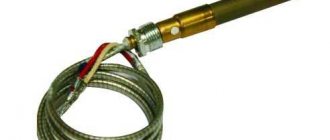
Thermoelectric sensors - thermocouples - are used exclusively in gas boilers and hot water columns equipped with non-volatile safety automatics. The element's task is to monitor the presence of a burner flame by continuously applying voltage to the solenoid valve of the SIT 630 control unit (or similar). Our goal is to tell you what a thermocouple is, how it works and changes in the event of a malfunction.
Thermoelectric flame sensor device
The thermocouple is a safety element of a gas boiler that generates voltage when heated and keeps the fuel supply valve open while the pilot light is on. The sensor shown in the photo operates autonomously, without connecting an external power source. The scope of application of thermocouples is gas-using non-volatile installations: ovens, kitchen stoves and water heaters.
Let us explain the principle of operation of a thermocouple for a boiler, based on the Seebeck effect. If you solder or weld the ends of 2 conductors from different metals, then when this point in the circuit is heated, an electromotive force (EMF) is generated. The potential difference depends on the temperature of the junction and the material of the conductors, usually in the range of 20...50 millivolts (on household appliances).
The sensor consists of the following parts (the device is shown in the diagram below):
- a thermoelectrode with a “hot” junction made of two dissimilar alloys, screwed with a nut to the mounting plate next to the boiler pilot burner;
- extension cord - a conductor enclosed inside a copper tube, which simultaneously plays the role of a negative contact;
- positive terminal with a dielectric washer, inserted into the socket of the automatic gas valve and secured with a nut;
- There are types of thermocouples that are connected to automation using conventional screw terminals.
Note. A copper tube is needed to protect the positive conductor from external noise created by a 220 V household network and other electrical appliances. Remember: the minimum thermocouple voltage is only 20 mV.
For the manufacture of electrodes that generate EMF, special metal alloys are used. The most common thermal couples:
- chromel - alumel (type K according to the European classification, designation - THA);
- chromel - copel (type L, abbreviation - THK);
- chromel - constantan (type E, designated THCn).
Reference. Alumel is an alloy of nickel with aluminum, manganese and silicon. The composition of chromel is 90% nickel, 10% chromium. Copel also includes nickel combined with copper and silicon.
The use of alloys in the design of thermocouples is due to better current generation. If you make a thermal couple from pure metals, the output voltage will be too low. Most heat generators used in private homes have TCA (chromel - alumel) sensors installed. For more information about the design of thermocouples, watch the video:
Operating principle of the boiler
The connection diagram of the thermoelectric sensor in various gas-using devices is approximately the same. The measuring electrode is located in the area of action of the wick or the main burner, the conductor is connected to an electromagnet that opens the gas supply.
Reference Information. In turbocharged and atmospheric heat generators connected to the house electrical network, a photoelectric sensor can be used instead of a thermocouple. It detects the presence of fire without direct heating.
How does a thermocouple work on floor-standing boilers of the AOGV type and similar devices:
- The user presses the button with one hand and forcibly opens the gas supply solenoid valve.
- With the second hand, the homeowner turns on the piezo ignition while holding the first key. The pilot lights up.
- According to the operating instructions, the button must be held for 5-30 seconds (depending on the model of the unit), during which the wick warms up the measuring electrode.
- A direct current appears in the electromagnet circuit, coming from the thermoelectrodes. The user releases the key, but the fuel supply does not stop - the valve now holds the thermocouple voltage.
If, for various reasons, the fire goes out, heating of the thermoelement ends, and the EMF disappears. The electromagnet will turn off, the spring will close the valve and block the path of fuel.
Reference. Gas water heating units, independent of electricity, are equipped with automation from various manufacturers - EuroSIT, Zhukovsky, Orion and so on. The thermocouple works on the same principle everywhere - while the electrode is heated by the flame, the gas supply will be open.
The thermocouple electrode is located next to the igniter on all water heaters.
Differences from temperature sensor
In addition to the thermocouple, a thermal cylinder is connected to the automatic fuel valve of the boiler, which is responsible for turning off the main burner when the set coolant temperature is reached. Externally, the element flasks and copper connecting tubes are somewhat similar. An uninformed homeowner can easily confuse these sensors.
Let us list the main differences between a temperature meter and a thermocouple:
- sensor design - a cylindrical bellows made in the form of a copper flask with a sealed end;
- the thermal cylinder is connected to the gas automatics with a thinner capillary tube than the electricity-generating sensor;
- the heat-sensitive flask itself is installed inside the immersion sleeve or hidden under the casing near the water jacket, and is not attached near the igniter;
- The temperature meter does not detach from the automation at all or the size of the fastening nut differs.
Note. The thermal balloon operates on a different principle: when heated, a special liquid expands inside the flask. The pressure through the capillary is transferred to the automatic valve, which turns off the main burner. The igniter flame does not go out.
How to check and replace a thermocouple
The main sign of a malfunctioning flame sensor is that the wick goes out simultaneously with the release of the button. Sometimes the problem manifests itself differently - the light on the igniter remains, but after igniting the main burner, the fuel supply is shut off again and the boiler goes out completely. Reasons for such problems:
- the thermal electrode is covered with soot and does not warm up well, causing the voltage in the circuit to drop below the minimum;
- burnout of the meter body;
- contact failure at the hot junction point;
- the fastening nut has been unscrewed, the working rod is skewed and is poorly heated by the igniter;
- the traction sensor has become unusable or its electrical circuit has broken.
Clarification. A malfunction of the draft sensor causes similar symptoms, since this “limit switch” is connected in series with the thermocouple (in an open circuit). To eliminate the influence of the sensor, temporarily short-circuit its wires.
For diagnostics, you will need a multimeter or other device capable of measuring low voltage (up to 100 mV). How the check is performed:
- Close the gas supply to the heat generator or instantaneous water heater using the tap located on the supply pipe. Remove the casing or front panel of the unit.
- Using open-end wrenches, unscrew the nuts securing the thermoelectrode and connecting tube. Remove the flame sensor.
- Carefully inspect the working electrode, clean it of soot with a brush and rag. If burnouts are detected during a visual inspection, the thermocouple must unconditionally be replaced.
- Moving to the kitchen, light the gas stove burner. Connect the multimeter clamps to the center terminal and the copper tube. Set the lowest measurement limit – 0.1 or 1 V.
- Heat the thermoelement with a gas stove burner while observing the voltmeter readings.
The main condition: a working thermocouple for the boiler must produce a voltage of at least 0.02 volts. If the device shows zeros, the voltage fluctuates or does not exceed 20 mV, the element needs to be changed. Modern sensors cannot be repaired by re-soldering.
Advice. When buying a new thermocouple, always be guided by the brand and specific model of the boiler, so as not to get confused in the markings and designations.
If you don’t want to remove the element ahead of time, diagnostics can be performed directly on the boiler. After unscrewing the nut, disconnect the thermocouple tube from the automation and connect the multimeter as described above. While holding the key, light the igniter and take readings from the device. Disadvantage of the method: the impossibility of visual inspection and cleaning of the electrode from soot.
When installing a new thermocouple in a gas boiler, adjust the position of the heated rod. Ideally, the electrode is horizontal, does not deviate up or down, and is well washed by the flame of the wick.
Conclusion
Knowing the structure of the boiler thermocouple and how to check it, it is easy to identify the problem, as well as replace the sensor at home. Here it is important to isolate other faults - breakdown of the traction sensor or electromagnet coil. The last problem is typical for domestic automation models - Arbat, ZhMZ, and so on. How to make repairs using improvised means, see the latest video:
Flushing
How to clean the heat exchanger of a gas boiler from scale with your own hands? If there is a small amount of plaque inside, you can get by with manual washing using a citric acid solution.
If there is a thick layer of scale, you will need a washing unit that will circulate the detergent for several hours. A 10-liter tank with a pump is suitable for this purpose (you can use a circulation pump from the circuit). Two hoses from the pump are connected to two heat exchanger pipes.
There are three cleaning methods:
- mechanical;
- chemical;
- hydrodynamic.
In the first case, you can use a brush, scraper, or vacuum cleaner to remove plaque. Heat exchanger parts are pre-soaked in cleaning solutions.
During chemical treatment, an acid wash solution is pumped into the system using a booster and driven through a heat exchanger for several hours. Acidic solutions are good at removing ferrous and carbonate sediment. At the end of cleaning, the product is drained and a neutralizing agent is added.
The hydrodynamic method is the injection of water with abrasives into the system under pressure. In this way, the internal surfaces are cleaned mechanically, but the cleaning efficiency is higher than when processed manually. Flushing can be done without dismantling the system, but it is quite expensive. When cleaning yourself, you need to monitor the pressure in the circuits to avoid rupture of the heat exchanger.
Connection nuances and verification
Connect the thermoelectric converter to the measuring device using a compensation cable. In order to minimize the measurement error as much as possible, the cores of this wire are made of the same material as the sensor itself.
Check the functionality of the thermocouple as follows:
- one end of the device is connected to a multimeter;
- the other end is manually heated using a lighter or gas torch.
To check the functionality of the thermocouple, connect one end of the device to a multimeter.
If the device is in good condition, this is indicated by the presence of a voltage in the region of 50 mV.
Connection methods
The most common two methods of connecting a thermocouple to measuring transducers are simple and differential. In the first case, the measuring transducer is connected directly to two thermoelectrodes. In the second case, two conductors with different thermo-EMF coefficients are used, soldered at two ends, and the measuring transducer is connected to the gap in one of the conductors.
For remote connection of thermocouples, extension or compensation wires are used. Extension wires are made of the same material as thermoelectrodes, but may have a different diameter. Compensation wires are used primarily with noble metal thermocouples and have a composition different from that of thermoelectrodes. Requirements for wires for connecting thermocouples are established in the IEC 60584-3 standard. The following basic recommendations can improve the accuracy of a measurement system that includes a thermocouple sensor:
— A miniature thermocouple made of very thin wire should only be connected using larger diameter extension wires; — Avoid, if possible, mechanical tension and vibration of the thermocouple wire; — When using long extension wires, to avoid interference, you should connect the wire screen to the voltmeter screen and carefully twist the wires; — If possible, avoid sharp temperature gradients along the length of the thermocouple; — The material of the protective cover should not contaminate the thermocouple electrodes over the entire operating temperature range and should provide reliable protection of the thermocouple wire when working in harmful conditions; — Use extension cables within their operating range and at minimum temperature gradients; — For additional control and diagnostics of temperature measurements, special thermocouples with four thermoelectrodes are used, which allow additional measurements of circuit resistance to monitor the integrity and reliability of thermocouples.
Working with AOGV
It begins when the gas supply is blocked - the corresponding valve closes. And this is a general principle for similar work with any boilers and columns.
How to clean the burner of an AOGV gas boiler? After shutting off the gas, this element is removed from its position. The burner has a nozzle
It is carefully unscrewed and carefully cleaned with a brush. The burner itself is cleaned by blowing using a special pump
Then the nozzle and burner are returned to their place.
These are general criteria. And the details are presented on the next two models.
First. AOGV 11.6-3. This is a reliable and practical device.
But after a certain period of operation, it is thoroughly cleaned. The process goes like this:
The burner block is removed
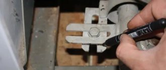
To do this, the pan of the apparatus is rotated, and three tubes are disconnected from the automation unit: contact, gas and thermocouples. Carefully unscrew the nuts located on the fittings of the automation mechanism. The paronite gasket on the main gas pipe is removed and its conditions are studied. If it is damaged, it needs to be replaced. The marked pallet is taken out through the groove, which is as close as possible to the tubes
The casing is also pulled out along with it. When fixing the lower part of the tray, point it towards you and remove the remaining holders (two pieces) from the engagement. This entire assembly falls to the floor. The main burner is examined and cleaned. The igniter nozzle is inspected. The wick and thermocouple are unscrewed. The box-shaped casing is separated from the pilot burner. This clears the way to the nozzle. If it is brass and there is plaque on it, it can be removed with fine-grained sandpaper. Cleaning the nozzle. To do this, thin copper wire and a blowing method under high pressure are used. The second action is carried out by a special pump on the side where the tube is connected to the tee. The same sandpaper is used to very carefully clean the bend of the thermocouple tube.
After this work, all the parts are assembled using the reverse algorithm. Smoothly, avoiding distortions, lift the entire block. The burner should be inside the housing, and the igniter and thermocouple should not touch the casing flange.
From the side of the tubes, the entire assembly should be tilted towards itself with a slight downward slope. The opposite side of the tray should rise.
Then feed it forward and simultaneously put on a pair of distant holds. They should be on the casing flange. The nearest hook goes to a cut groove. After it enters there, the entire pallet rotates in the opposite direction to the clockwise direction. The gas pipe should be positioned only under its branch pipe of the automation unit.
Next, it is tested how correctly the gaskets fit, and all the tubes are returned to their places. The wrench tightens the nuts on two tubes: the igniter and the gas tube.
Before reassembling the thermocouple tube, its contact areas are carefully but carefully cleaned. The nut here is tightened with your fingers.
The final stage is to check the tightness of all connections for potential leaks. If they are absent, the boiler turns on. If available, these places are covered with sealant, the nuts are tightened.
The second model is AOGV-23.2-1 Zhukovsky.
It works like this:
- The nut is unscrewed so that the gas pipe passes through.
- The angle, igniter and thermocouple are unscrewed.
- All burners in the set stretch outward and extend to the side towards the user. If there are difficulties with their movement, loosen and unscrew the studs with pliers. Clean all jets and other components.
- Disassembly of burners. To do this, unscrew 4 pins on both sides.
- The plates with slots are removed from the top of the burners, then the springs. All parts are thoroughly cleaned.
- Reassemble all elements in reverse order.
After reassembly, a leak test is carried out to examine how tightly the burners adhere to the body.
Pilots and gas burners for boilers
The igniter and burner are one of the most important components included in the design of gas-fired boilers. Their main purpose is to put the boiler into operation and heat it up.
Igniters for gas-fired boilers
The igniter of a gas boiler is a hollow copper tube, at one end of which there is a nozzle, and at the other there is a clamp (a piece of pipe for connections) for connection to the automation unit.
The igniter is designed to pass gas through itself and continuously maintain a burning torch to heat the thermocouple and start the main burner.
The igniter replacement occurs in two variations:
- when it becomes clogged with various debris present in natural or liquefied gas
- in case of mechanical damage
Burners for boilers AOGV, AKGV and KOV-SG
Over the entire history of production of Zhukovsky AOGV/AKGV boilers, 4 types of burners were used. They can be classified according to their design and materials from which they are made.
The very first boilers were equipped with a cast-iron round burner, reminiscent of a car steering wheel. Then there was a short period when a steel burner produced in St. Petersburg was used. Modern boilers use two types of burners - 7- and 13-nozzle stainless steel made in Italy by Polidoro. These burners are included in the design of all AOGV/AKGV gas burners produced today at JSC ZhMZ.
The most powerful boilers 43, 50, 68 kW of the KOV-SG series are equipped with a slot burner made of stainless steel, the production of which is established at JSC ZhMZ. The main design advantage of Polidoro burners is their ability to be converted to liquefied gas by replacing the nozzles on the burner itself.
The main task of the burner of a gas boiler is to heat the heat exchanger tank, or, to be more precise, its part located below - the fire box.
Replacement of the burner is done, for the most part, after its service life has expired. This can be determined by the following signs:
- uneven intensity of torch burning (flame pulsates)
- burning of the torch is not on the entire plane of the burner or beyond (through cracks)
- soot formation
In order to properly purchase a burner for a boiler or igniter, it is important to know what power and series the boiler is, its month and year of manufacture.
Other models
In practice, cleaning burners follows the same principles. The differences lie in their removal and reassembly.
The following examples are provided:
For example, the Helios AOGV 4 parapet apparatus is equipped with Eurosvit 360 automation and burners of the European brands Bray and Polidoro.
The burner set is removed following the example of the Zhitomir process. A pump is used to clean the nozzle, and hard brushes are used to clean the surfaces.
The Conord line stands out in particular.
The automation variations here are:
- AGU-T-M (Russia),
- "Eurosvit" (Italy),
- Honeywell (USA).
The most popular is the second variation:
It includes a sectional burner, Polidoro tubes, igniter, thermocouple, gas valve, temperature indicator and wires.
A similar system is available in the Lemax Premium 12.5 model.
Only the burner here is micro-flare. The mechanism is very easily removed by removing the top cover and lightly unscrewing the fixing bolts.
Its analogues are also found in the Siberia models.
Ecological burners "Vorgas" are used here.
Does not lag behind in this regard. Here its models Novella Maxima 108 N RAI and Mynute Boiler stand out.
Honeywell automation looks like this:
It has a similar operating principle to the Eurosvit system. The differences lie in the materials of some components.
It is often found in wall-mounted modifications, for example in Baksi Fortech 24
It also has an ecological burner that leaves no combustion products.
An equally popular device is the Ariston ALTEAS X 24 FF NG.
Many Daewoo models operate with similar automation. For example – DGB 200 MSC.
Whatever model or brand you have, strictly follow the suggested instructions for removing and reinstalling the burner block. Clean it thoroughly with the right products 1-2 times a year. Maintain other mechanisms as well. And then your boiler will work properly for a long period.
Causes and consequences of clogging
Energy-dependent ones are in turn divided into:
- gas processing;
- electrical installations;
- solid fuel and liquid fuel equipment;
- combined models.
Volatile boilers may turn off for a number of reasons:
- voltage drops and surges in power lines
- lack of electricity
- factory settings failure.
Often used in homes: AOGV, Zhukovsky boiler, gas “Ochag”, Lemax, Signal, Conord.
Do-it-yourself furnace: drawing, operation diagram. Read here.
Connection to the city water supply network: documents, prices:
Mechanical ones may work intermittently due to wind flow entering the chimney. In addition, due to insufficient oxygen, the flame may go out
You should pay attention to the hood (cheaper models do not always have it)
If the chimney becomes dirty, modern devices have a warning system that will notify you of problems and the need for cleaning.
How to check it
Keeping your home safe is a working thermocouple sensor. Several times a year, the thermocouple requires mandatory checks and adjustments. To do this, invite a specialist who will perform a safe and accurate analysis of the device.
When checking thermocouple readings, consider the measurement quality of the device itself by systematically checking its operation.
Reasons for incorrect operation of the thermocouple:
- incorrect soldering of two metal rods;
- presence of electrical noise;
- you smell gas, there is a leak;
- thermoelectricity is inhomogeneous.
To resolve these issues, during device installation you should:
- choose a thermocouple with thick and large wire;
- avoid temperature changes;
- do not allow tension and vibration of the metal wire;
- use a sensor that has a working temperature spread.
You need to check the serviceability of the thermocouple by following the step-by-step instructions.
- The thermocouple has two ends. When checking, one of them must be heated with a flame from the igniter, and the second must be secured to the thread of the valve (electromagnetic) using a nut.
- The next step is to separate it from the boiler. Then you need to ensure a stable flame. A gas burner is also used for this purpose. But experts advise using a candle flame.
- The tip of the device is immersed in the flame, it should be approximately 1 cm above the flame. Here you need to remember that the fire heats the device to almost half, so it is better to hold it by the tip.
- Next, a tester is used that determines millivolts. It is connected to the output contact and to the body of the thermocouple itself.
- If the thermocouple is working properly, then 30 seconds after heating the result will be from 17 to 25 mV. But if this indicator does not exceed the minimum threshold, then this means that it is faulty.
You can find out more about how to replace a thermocouple on a gas stove.
The thermocouple for a gas boiler is a thermoelectric converter for automatic control and monitoring systems of gas equipment. The device serves as the main element of gas control protection and is designed to ensure the fastest possible shutdown of the gas supply in the event the flame goes out.
Design and purpose of a thermocouple
Sensor elements, which are structurally a thermocouple, have found wide application not only in household appliances, but also in industrial equipment. Essentially, a thermocouple should be considered a thermoelectric converter.
Typically, such a converter is used to measure ambient temperature. In particular, if you examine how a thermocouple works in the design of a gas boiler, you can note that thanks to such a sensor, the temperature of the gas burner flame is monitored (measured).
This is approximately what a thermocouple looks like externally, but not for all exclusively geyser designs. Individual pieces of equipment may be equipped with sensors of a different configuration
Design features of the thermocouple
The design of the thermocouple is not particularly complicated, but from a technological point of view, the manufacture of this element requires high precision and compliance with the characteristics of the components used.
Actually, the main components of the sensor are two metal elements with different physical properties.
These elements (wires) are soldered at the ends on one side, while the end parts of the other side remain free - they are used to connect to the thermo-EMF converter and transmit the potential difference.
Schematics of a classic thermocouple: 1 – junction point (actually a control element); 2 – metal with one EMF value; 3 – metal with a different EMF value; 4 – voltmeter, with which you can take readings in millivolts when the sensor heats up
Operating principle and purpose of the sensor
The thermoelectric effect (in other words, the Sebbeck effect) determines the operating principle of the device in question. Conductors made of different metals connected at one point form a potential difference, taking into account the fact that different metals have different thermo-emf coefficients.
In relation to a gas water heater, the operation of a thermocouple provides combustion control and protection from possible gas contamination. When the burner of a gas boiler or water heater operates in active mode (throws out a flame), a thermocouple installed in the flame zone generates an electric current under heating. The current is sufficient to control the opening and holding of the gas valve.
A classic type diagram for geysers, clearly showing the operation of the equipment: 1 – flame control sensor/thermocouple; 2 – relay providing thermal protection; 3 – mechanics of the solenoid valve
If the heating temperature drops sharply (burner flame goes out), the amount of current generated also decreases, which results in the closing of the gas valve. Accordingly, the gas supply to the system is blocked, which ensures safe operation of the equipment.
If the gas valve on your gas water heater does not work, we recommend that you familiarize yourself with the testing and repair methods.
Date: September 25, 2022
Cleaning methods
Cleaning is carried out in two ways: mechanical and chemical
Mechanical cleaning
The cleaning method is imperfect and involves mechanical action. Soot should be carefully removed so as not to damage the internal surface of the boiler and parts, which can subsequently lead to metal corrosion. Often the tools come with the boiler - these are pipe cleaners, brushes and scrapers. It is also possible to use air cleaning, when warm air is supplied under pressure.
Dry cleaning
It is recommended to apply cleaning agents while wearing PPE (personal protective equipment); rubber-based gloves are usually used, this will protect the skin from interaction with harmful substances. Chemicals clean not only soot, but also metal, which can further lead to its destruction. This method is best used on minor dirt and small areas of contamination.
Hydrodynamic cleaning
Hydrodynamic cleaning or how to clean soot from a diesel boiler.
It is used in boilers with a small thickness of contamination, as well as when speed of execution is required. Equipment for such washing consists of:
- pump and
- containers with water supplied under high pressure.
Thanks to this cleaning, soot and soot are removed quite quickly, but this method can only be used by specialists and is not recommended at home.
Booster cleaning
The procedure for flushing the heat exchanger with a booster (using the example of cleaning a Zhukovsky boiler from soot):
- First you need to disconnect the pipes from the heating system.
- Next, connect a booster hose to one of them to supply the reagent.
- We connect the second pipe to the second end of the hose. The spent reagent will be removed through it. This closes the system and the reagent will circulate through the pipes.
- After cleaning, the solution must be drained from the tube.
- Rinse the heat exchanger itself with sufficient water.
Booster is a device for chemical cleaning. Thanks to it, the reagents circulate autonomously.
During such cleaning, it is recommended to change the reagent several times, since the old one gradually reduces its properties. This method is most often carried out by specialists.
Equipment setup
Floor-standing gas boilers with an atmospheric burner can be configured independently. Pressurized systems are regulated by an automatic control unit and do not require additional configuration.
Scheme of actions for setting up single-stage equipment:
- Install the device on the boiler.
- Connect to the gas pipe.
- Check for absolute tightness.
- Remove the burner housing.
- Using a pressure gauge, measure the gas pressure at the inlet.
- Connect to electricity. Make sure that the jumpers and phases are connected correctly.
- Place a gas analyzer in the chimney pipe.
- Start the device.
- Using a pressure gauge, take pressure readings at the outlet of the burner block. Pressure readings must correspond to the parameters indicated in the data sheet.
- Adjust the air flow using the air damper.
- The gas analyzer readings must also comply with all gas equipment installation standards.
Setting up gas equipment should be carried out by specialists. The simplest open-type boilers can be configured independently if you have certain skills and knowledge of the design of the burner unit. The efficiency of the boiler, its level of efficiency, and fuel consumption depend on the quality of the burner. It is possible to superficially determine that the equipment is malfunctioning by the changed burner flame.
An effective way to descale
To carry out the highest quality cleaning of equipment, you can use a modern device - a booster. It will effectively solve the problem of how to flush a gas boiler from limescale.
What does the booster include:
- circulation pump;
- container for loading reagents;
- electric heating part.
The booster functions as follows:
- the reagent is heated in a special container (in order to increase its cleaning properties);
- the circulation pump pumps the heated reagent into the coil;
- chemicals circulate through the heat exchanger and clean the walls;
- the spent reagent with dirt pours out.
The heat exchanger must be cleaned regularly, at least once a year. However, this procedure can be repeated more often if the quality of the coolant is very low. If ordinary tap water is poured into the system, then it is very simple to determine this: observe how quickly scale forms on the kettle. Hard water “suffers” from this deficiency.
Burner: cleaning gas nozzles yourself
The burner in gas boilers of various types is considered a significant part of the entire structure, since it performs the main function - supplying fuel. As a result, it should be cleaned first once a year, before the boiler is started.
The burner and jets can be cleaned separately, but it is better to do this in combination. When starting work, you should check whether you have disconnected the device from the gas, and only then proceed with the cleaning itself.
The burner includes nozzles that also need to be cleaned. Not only the heat in the room, but also the low consumption of all fuel, and in addition the operational period of this device, depend on a similar important detail.
Clean the burner and its nozzles:
- Turn off the gas supply with the key;
- Remove the burner from the installation site;
- Unscrew the injectors;
- Clean the injectors carefully with a brush;
- We clean the burner itself with a special brush, but its holes need to be blown out;
- Insert the nozzles into the burner;
- Install the burner in its old place.
You can also step by step clean all other parts that are responsible for the operation of the entire boiler.
How to clean an AOGV boiler
For this operation you will need a regular plastic bottle cleaning brush. It can be purchased at a hardware store and is perfect for cleaning vertical channels. Tie it with electrical tape to a wooden stick so that you can easily go through the channels along their entire height. In order not to spread excess dirt in the boiler room, take everything that can be moved out into the yard for cleaning.
- Start cleaning from the top plane of the heat exchanger, clean off and sweep down all the soot.
- Then comes the turn of cleaning the channels. The soot will come off the walls quite easily if it has not yet hardened, otherwise you will have to make some effort.
- After completing the cleaning process of the boiler itself, proceed to the removed components and parts. Clean the top cover of the heat exchanger. After this, remove layers of soot on the top cover of the boiler itself and from the hood.
- Lastly, use a brush to brush away the soot that has accumulated from above from the burner block; the burner itself is already clean.
Immediately lightly clean the tube with fine sandpaper. This completes the process of cleaning the boiler and its parts. Proceed to reassembling the AOGV boiler.