The TIM JH-1036 pumping and mixing group has an adjustable bypass. There is a scale with a gradation from 0 to 5, but it is no longer possible to find out what these numbers mean after installing the bypass. It is difficult to understand why it is needed, because other mixing units for heated floors do not have such a device.
I had to study in great detail the operation of the bypass of the mixing unit as a result of incorrect connection of its input and output to the heating system.
After the previous installation of the TIM JH-1036 mixing unit, it was not possible to configure the bypass, since there are no instructions for setting it up, and I did not study the design before installation - do not remove it. Now, before installation, I studied and took photographs of the internal structure of the mixing unit.
What regulates the bypass of the TIM JH-1036 mixing unit.
The mixing unit has a conditional mixing chamber through which the underfloor heating circuit and the boiler heating circuit pass.
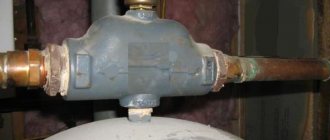
Typically, a heated floor mixing unit has one adjustment parameter - the water temperature in the heated floor circuit. The TIM JH-1036 mixing unit also has some kind of bypass, and even adjustable. And this is not the bypass balancing bypass, which is triggered by excessive pressure developed by the pump.
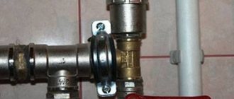
The pressure balancing bypass can be seen in the photo - the rightmost personal belongings.
I need it because it is possible to block all heating directions of the heated floor as a result of automatic regulation. By the way, I still haven’t figured out how to regulate the balancing bypass TIM M307-4 - maybe someone can tell me.
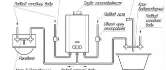
As for the mixing chamber bypass, you can find the following graphic explanation of the operation of the mixing unit bypass:
Little is clear from these diagrams.
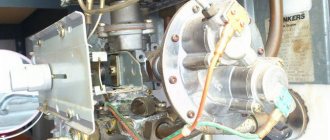
Moreover, it is not clear what the numbers on the scale mean and what the current value is tied to. All this can be found out only by holding the TIM JH-1036 mixing unit in your hands:
It turns out that the adjusting screw turns the cylinder, which has a slot that closes when turned. Through this slot, water can be pumped by a circulation pump, bypassing the conditional mixing chamber.
It should be taken into account that the sticker with a scale from 0 to 5 can be pasted arbitrarily.
The maximum opening of the slot (pictured above) corresponds to setting the adjusting screw to position 5 (pictured below).
The technological ledge on the mixing chamber body can be taken as a conventional point for reading the scale value. When the scale value is 0, the gap is maximally closed. In this position, all the water pumped by the circulation pump along the contours of the heated floor passes through the mixing chamber.
With the bypass completely closed, the thermal power of energy taken by the mixing unit from the heating system is maximum.
If the bypass is completely open, then part of the water circulates through the heating circuits without entering the mixing chamber - and the thermal power of extraction is minimal.
But in practice it turned out that not only thermal power is regulated by the bypass.
How to make a device yourself
Making a distribution unit yourself is not too troublesome and not at all expensive, so this option is increasingly being chosen by home craftsmen who want to save money on purchasing such an expensive device.
Drawing up a drawing
Before you begin assembling the comb with your own hands, you need to draw up a competent drawing or diagram of such a device, taking into account the number of circuits, load and other basic parameters.
A pre-compiled assembly diagram for the distribution unit allows all work to be done correctly, with the highest quality and speed.
Selection of the required material
To make a comb with your own hands, you will need to purchase a few of the simplest parts presented:
- ½ inch brass tee - four pieces;
- ball valve with a ½-inch threaded connection - five pieces;
- silicone sealant;
- standard ½" plug.
The purchased tees must have a configuration in which there is an internal thread on one side of the product, and an external thread on the opposite side.
Manufacturing
The sequence of self-manufacturing of a distribution comb for a “warm floor” heating system:
- Assemble the tees into a single line. To connect each subsequent tee to the previous one, external and internal threads are used, which allows you to get a straight pipe with side branches. Reliable sealing of all connections involves treating the threaded connections with silicone sealants applied to the external threads. All excess sealant must be removed using a rag.
- A standard tap is installed on the inlet part of the resulting straight pipe using silicone sealant and a threaded connection.
- A plug is installed on the opposite side of the base on a homemade comb.
- All side branches are provided with screw-in and sealable taps.
The homemade distribution comb obtained in this way is perfect for arranging a four-circuit “warm floor” system.
An equally popular option is to independently solder the comb using conventional polypropylene pipes and additional fittings. The number of tees is selected individually, and the sections of PPR pipes must have a diameter similar to them. With this option, cut pipes serve as connecting nipples for joining tees.
Video: homemade collector
https://youtube.com/watch?v=jm7lnGZZdkw
Heating a room using a modern and highly efficient “warm floor” system is one of the most practical options in terms of saving energy resources and uniform distribution of thermal energy. When installing this type of heating over a large area, it is mandatory to use a special comb with manual or automatic control.
The use of automation in the comb control system is an ideal option that allows you to obtain the maximum level of economic benefits when consuming thermal energy. However, such a device belongs to the category of non-public and inertial, so warming up and cooling of the underfloor heating system will take some time.
Experimental determination of the value set by the bypass.
Before installing the bypass, it would not hurt to make sure what value corresponds to the full opening and closing of the bypass.
Just be careful - the edges of the crack are sharp, like blades.
If the mixing unit is already installed, but the sticker with the 0-5 scale is affixed differently, you can carry out an experiment.
By turning the adjusting screw with a 10mm wrench, find out what position of the scale is the maximum and minimum water flow rate on the flow meters of the underfloor heating manifold.
If there is no collector or flow meters, which is very in vain, you can find the maximum and minimum temperatures at a limited temperature of the coolant in the main system (at the inlet to the mixing unit) and the maximum possible setting of the thermostatic head of the mixer.
The temperature of the coolant on the boiler is limited so that the mixer cannot cope with the set temperature.
How the bypass of the TIM JH-1036 mixing unit works.
It would seem: we set the thermal power of the mixing unit to maximum, completely closing the bypass slot - and that’s it.
But the flow meters of the underfloor heating collector make it possible to find out that not only the thermal power is regulated by the bypass. When the bypass is completely closed, the floats of the flow meters float up sharply.
It turns out that the water flow through the heating circuit with a completely open bypass is more than twice as much as with a completely closed one.
This is not surprising - pumping water through the mixing chamber requires pump power, which affects the speed of water flow.
At maximum thermal power of the mixing unit, the flow rate of water along the contours of the heated floor is minimal. To uniformly heat the entire underfloor heating circuit, it may be necessary to turn on the pump at second speed, which will increase the noise of the heating system.
It turned out that in my system the minimum thermal power of the mixing unit is sufficient to ensure a coolant temperature of 32 degrees at the supply manifold with all directions of underfloor heating open, even when starting a cold heated floor.
But in other cases it may be necessary to increase the selection power.
Step by step guide
Initially, before starting installation of the system, the room is cleaned and the working surface is prepared for work.
Further work is carried out in the following order:
- according to the working design, a protective cabinet is installed;
- the inlet pipeline from the boiler and return supply are installed;
- the necessary valves and actuators, sensors, a Mayevsky valve, and a safety valve are mounted on the supply and return manifolds;
- mounted on the cabinet wall according to the collector diagram;
- a circulation pump and sensors are installed;
- coolant pipelines are laid on the floor;
- pipelines are connected to collectors;
- the control unit is installed;
- the system is filled with water, a cold test is performed;
- leaks are eliminated;
- The system is tested in operating mode.
How does installing a bypass mixing unit TIM JH-1036 affect the heating system.
It was necessary to carefully study the operation of the mixing unit as a result of incorrect connection of the mixing unit to the heating system.
Different positions of the bypass adjustment led to the fact that different pipes connecting the mixing unit to the heating circuit were warm.
That is, the supply and return of the mixing unit swapped places when the bypass adjustment position changed. Mystic.
So I found out that I made the connection incorrectly, having mixed up the supply and return to the mixing unit .
Theoretically, the circulation pump of the heating floor mixing unit should not have influenced the heating boiler circuit in any way - the mixing unit pump releases water at the same point from which it takes it. The circulation pump of the mixing unit pumps water along the contours of the heated floor, and the boiler circulation pump pumps water through the mixing chamber of the mixing unit.
But involuntary experiments made it possible to find out that even the minimum power of the mixing unit pump with a closed bypass is enough to carry out additional circulation in the main heating circuit.
This is possible if we assume that the equivalent circuit (by analogy with problems in electrical engineering) of a heating system with a TIM JH-1036 mixing unit is as follows:
Where “R1” and “R2” are resistances in the mixing chamber, regulated by the bypass.
“Boiler circuit” is an old heating system with radiators and a boiler.
It’s not for nothing that the mixing unit clearly indicates which pipe should be the supply pipe. The photo shows a correctly connected mixing unit.
Then I decided that it wouldn’t hurt to familiarize myself with the theoretical foundations of the operation of water-heated floors, and as a result I created a page with links to the theory.
Optimal temperature parameters
The preferred temperature of the heated floor is selected according to individual needs. After all, some people like invigorating freshness in the house, while others want to bask in the warming energy flows. However, there are generally accepted standards for the preparation of coolant, heating of floor coverings and, accordingly, indoor air. They are determined by sanitary and technological requirements. These standards have already been mentioned here, however, let us briefly recall:
- The optimal floor surface temperature is 280C;
- if the room is designed for a long stay of residents or there are other heating sources, then it is advisable to reduce the temperature to 22-260C - this energy mode is optimal from a medical point of view. In addition, heating of the coatings is unnoticeable upon bodily contact with them, which does not cause tactile discomfort;
- for rooms where the heat supply is the only source of heating, as well as where residents are present only periodically (bathroom, toilet, hallway, loggia, covered veranda), the surface temperature of the floor covering can be raised to 320C.
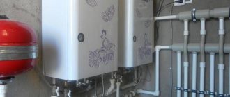
Two pumping and mixing units for underfloor heating in one heating system.
I ended up with two underfloor heating mixers in one heating system.
I made one right away at the first stage of repair and installed it temporarily.
So far, this mixer has controlled one branch of the heated floor. Then he intended to move it after the renovation was completed in other rooms. I laid pipes in the floor to connect this branch to the mixer in a new location.
But nothing is more permanent than temporary.
And in a new location he installed another similar mixer.
Someday I will remove the first mixing unit - the manifold of the second mixing unit has fittings for connecting this branch and the pipes have already been laid.
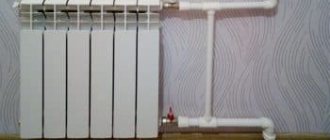
Please note that the mixer in the first photo is not capable of providing a coolant supply temperature of more than 25 degrees when the temperature set on the boiler is 50 degrees.
The photo shows a coolant temperature of 30 degrees, achieved when the boiler temperature is 60 degrees and the thermostatic mixer head is set to 40 degrees.
This is understandable with such a connection.
The paradox is that this (25 degrees) is enough to relatively quickly heat the room by a couple of degrees, maintaining the set temperature.
Select the bypass adjustment value 0-5 depending on the situation.
Using the example of these two mixers, we can now show the difference between the different bypass adjustments of the TIM JH-1036 mixing unit.
Bypass setting value is 0.
The first mixer operates in conditions where the bottleneck of the system is the heat supply from the system.
It is connected like a radiator in a one-pipe system.
Just in case, I made a thickening at the connection section from 25 to 32 diameters and installed a tap, since I doubted that a sufficient amount of water would flow in and provide sufficient power.
This local heating subsystem is built, of course, on one mixing unit without a collector group.
There should be no problems with circulation along one circuit.
Therefore, we set the value of the bypass adjustment bolt to 0.
We make the circulation through the heated floor circuit minimal, and the circulation through the mixing chamber maximum.
It was shown above that here the mixer pump will help the circulation through the heating system a little more.
Bypass setting value 5.
In this case, on the contrary, the heated floor mixer is connected directly to the boiler in parallel to a single-pipe system with batteries.
There are no problems with supplying the required thermal power to the mixer.
But turning 4 heating circuits will not be as easy as one.
Therefore, we set the bypass adjustment value to 5.
We make the circulation through the heated floor circuit maximum, and the circulation through the mixing chamber minimal.
In addition, with such an installation we further limit the influence of this circulation pump on the main system.
Passport TIM TIM JH-1036 pasport-smesitelnogo-uzla-tim-jh-1036.pdf
Twin passport Profactor PF MB 841 pasport-mb_841_nasosno_smesitelnyj_uzel.pdf
- How I adapted the TIM JH-1036 mixing unit for underfloor heating. How much does it cost and where to buy equipment for a TIM warm field - Estimate
- How to set up the bypass of the TIM JH-1036 mixing unit
Self-assembly
Assembly diagram
You can assemble the collector yourself. As a rule, the manufacturer includes a detailed wiring diagram in the kit. The following types of work will be required:
- The equipment is fixed in a horizontal position on the wall or in a niche. The main requirement is to provide access for servicing and managing node elements. If the collector is not installed in a separate room, but in a bathroom or hallway, it must be disguised for aesthetic purposes by installing it inside the collector cabinet.
- Heated water from the boiler is supplied from below, and a “return” is mounted on top. To install shut-off valves, select an area in front of the frame, and install the pump after them. With its help, the “return” and hot water will be mixed, and the optimal pressure in the pipes will be maintained.
- Install the bypass valve and distribution comb.
- After this, it is necessary to install the pipes. Those that go to the floor are fixed at the top, and the pipes from the heating system are fixed at the bottom.
- When connecting the manifold, components are used in the form of compression fittings, which include a support sleeve, a clamping ring and an intermediate brass nut.
- When the installation work is completed, they begin to check the tightness of the connections - pressure testing. To do this, use a special pump to increase the pressure in the system and leave it for 24 hours. The collector unit is completely ready for operation if the initially set pressure value has not changed during the day.
If you lack experience when assembling the collector yourself, the following mistakes may be made:
- Incorrect bypass setting due to incorrect calculations of the permissible load on the circuit. Such calculations must be performed before installation work begins.
- The absence of a separator leads to the formation of air pockets in the water kennels, which reduces the efficiency of the heating system.
- Wrong choice of hot water supply point. The coolant should come from above, not from below.
- Lack of a check valve, which will be needed to prevent leakage.
If the collector was initially assembled incorrectly, it will be problematic to subsequently eliminate errors and remake the system. Therefore, it is better to entrust the work to a specialist who will properly assemble and configure the equipment.