Even to the average person far from gas affairs, one name makes it clear that this is one of the elements of automatic boiler equipment. In fact, a thermocouple for a gas boiler is a key part of the safety system. Without a properly working sensor, the unit will not be able to operate, and new models with electronic units will not even start. Therefore, a thermocouple with problems must be changed, otherwise the gas boiler will fail.
How does a flame sensor work in a gas boiler?
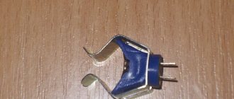
In appearance, a thermocouple resembles an ordinary copper tube with a fixing nut at the end. Despite its apparent simplicity, the gas boiler thermocouple device is optimized to obtain maximum sensitivity and reliability of the sensor.
The thermocouple consists of four parts:
- tip, head or hot junction of the temperature sensor;
- copper tube - extension cord;
- protective sleeve;
- contact protected by a dielectric washer.
The tip is a joint made of two dissimilar metals or alloys. Two small parts, one of which looks like a rounded cone, the second is the same cone, but smaller.
The inner cone of the tip is made of one alloy, it can be “copel”, inserted into the outer shell of “chromel”. Both parts are soldered under pressure so that a common surface is formed between them. The larger its area, the higher the sensitivity of the thermocouple and the lower the operating temperature.
The sleeve is made of bronze or brass, its task is to protect the seam between the thermocouple head and the copper extension. Inside the copper tube there is a copper conductor, which extends out and ends at a contact pad with an insulating dielectric washer. This end is inserted into the contact connector (+) on the AOGV and is rigidly fixed with a fitting nut. The hot junction is installed on a bracket next to the ignition device.
For gas boilers, an AOGV with a thermocouple, fixed by a fitting or an electrical block, is used. If you have the opportunity to choose, it is better to choose a model with a fitting nut.
The problem is that the voltage on the thermocouple is extremely low; for a chrome-copel junction it does not exceed 25 mV. This means that even slight oxidation of the contact surface can cause unstable operation of the gas boiler ignition system. In those models where the contact pad is fixed with a fitting nut, such problems do not arise.
Application
Thermocouples are used wherever temperature measurement in a process environment is required. They are used in automated control systems as temperature sensors. Thermocouple type TVR, which has an impressive thermoelectrode diameter, is indispensable where it is necessary to obtain data on very high temperatures, in particular in metallurgy.
Gas boilers, convectors, water heaters are also equipped with thermoelectric converters.
Advantages
- high measurement accuracy;
- fairly wide temperature range;
- high reliability;
- ease of maintenance;
- cheapness.
Flaws
The disadvantages of the products are the following factors:
- the influence of free junctions on instrument performance;
- limitation of the operating range by the nonlinear dependence of the thermal force on the degree of heating, which creates difficulties in the development of secondary signal converters;
- during long-term operation under conditions of temperature changes, calibration characteristics deteriorate;
- the need for individual calibration to obtain high measurement accuracy, within an error of 0.01 ºC.
Due to the fact that problems associated with shortcomings can be solved, the use of thermocouples is more than justified.
How does a "hot" alloy temperature sensor work in a flame?
The operating principle of a thermocouple is based on the physical phenomenon of thermoEMF. If you weld two conductors from different metals at one point and heat one of them and cool the other, a potential difference will appear at the ends.
In a thermocouple for a gas boiler, the outer surface of the junction head acts as a hot conductor, and the inner surface acts as a cold conductor. Heat is removed from it through a copper conductor. The temperature difference between outside and inside can reach several hundred degrees.
The voltage across the thermocouple when the gas burner is burning depends on the alloys and metals used in the junction. The most sensitive ones based on platinum group metals produce up to 50 mV for a long time. Sensors based on non-ferrous metals give 17-25 mV.
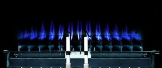
The temperature sensor is not immersed directly into the flame front. This cannot be done, since when the temperature sensor comes into contact with a hot gas flame, all parts will heat up to a high temperature, and the thermoEMF effect will disappear.
Therefore, they place the thermocouple at a distance of 3-4 cm from the igniter. This will ensure heating of the hot junction and normal cooling of the copper tube. Thermocouples are also installed in solid fuel heating boilers. For example, in the Lemax model the temperature sensor is installed above the grate.
Design
The operating efficiency and high accuracy of operation of this primary temperature sensor is based on a simple principle.
Its operation is ensured by the following basic design elements:
- A thermocouple junction made of 2 dissimilar conductors. Sometimes semiconductors can be installed instead of conductors.
- Insulated conductors that make up the circuit from the soldering point to the point where the signal is output to external current collectors.
- Shielding protective coating is a metal tube that covers the circuit wires from exposure to open fire in a gas torch.
Important! The composition of the junction can include both non-ferrous and noble metals. Depending on this, thermocouples are grouped into several modifications, the characteristics of which are presented below.
Main types of thermocouples for a gas boiler
There are many models of combustion front temperature sensors for gas equipment. There is even GOST R 8.585-2001 for thermocouples. They differ from each other in the length of the copper tube, the design and thickness of the hot junction head, and the method of fixing the contact pad on the AOGV block.
All models are available in standard lengths, from 30 to 150 cm in increments of 30 cm. The fitting nut can have an M8x1, M9x1, 11/32-inch thread or an M10x1 collet. For some AOGV models, a contact block-connector is used.
Thermocouples also differ in the alloys used.
| Thermocouple type | Spay | Marking according to GOST 6616-94 | Operating temperature ℃ |
| K | chromel-alumel | THA | up to 1300 |
| J | iron-constantan | TZHK | up to 1200 |
| N | nikhrosil-nisil | TNN | up to 1300 |
| R | platinum-rhodium-platinum | Chamber of Commerce and Industry13 | until 1700 |
| S | platinum-rhodium-platinum | TPP10 | until 1700 |
| B | platinumrhodium - platinumrhodium | TPR | until 1800 |
| T | copper-constantan | TMKn | up to 400 |
| E | chromel-constantan | THKn | up to 600 |
| U | copper-copper-nickel | THKn | up to 500 |
| L | chromel-copel | THC | up to 850 |
Four types of alloys are used for gas boiler control systems:
- type E is made by welding constant and chromel alloys. Operates at temperatures up to 740℃;
- type J is made on the basis of iron and constant. Operating temperature up to 600℃;
- type K has a junction made of aluminum and chromel. Works stably up to 1350 ℃ and has a fast response to temperature changes. For boilers operating on coal briquettes and gas fuel, it is not used due to high sensitivity to the increased content of CO, CO2;
- Type N works at temperatures up to 1200℃. Nichrosil and nisil are used in the junction. Has high accuracy. Used in high-power gas boilers.
In addition to thermocouples for non-ferrous metals, there are models based on a platinum-platinum-rhodium junction. They have high operational stability and low sensitivity to contamination by combustion products of gas and briquette fuels.
The cost of platinum thermocouples is an order of magnitude higher than chromium and iron ones, but temperature sensors on platinum-rhodium junctions are used mainly in industry. It makes no sense to try to install them on domestic gas boilers without shunting, since the operating voltage is almost twice the potential on the most common Chromel-Copel models.
Advantages and disadvantages
It would seem, why install an additional device in a gas boiler if there is already a heat sensor on the heat exchanger. As soon as the temperature of the copper walls and water rises by ten degrees, the automation will understand that gas fuel combustion occurs as normal. But it's not that simple.
Positive aspects of using a temperature sensor at a junction of two metals
The first and most important advantage of a thermocouple is its simple design and extreme reliability of the device. If the burner of a gas boiler is regularly maintained and adjusted, the combustion sensor can last 20-25 years.
Another plus is the slight inertia of the device. The thermocouple is activated within 20-25 seconds from the moment the flame appears or disappears. There have been attempts to simplify the design of a gas boiler and transfer the functions of the combustion front temperature sensor to a temperature sensor. But it turned out that the heating or cooling time of the sensor spiral is an order of magnitude longer than that of a thermocouple. Accordingly, a dangerously large amount of gas and air manages to accumulate in a gas boiler; the firebox could simply explode.
Disadvantages of using a thermocouple
There are few negative sides. The durability of the sensor depends on the quality of the gas, the completeness of fuel combustion and the intensity of soot deposition on the surface of the junction. If the gas is contaminated with volatile metal carbonyls and vapors of heavy petroleum products, then the head of the junction becomes covered with a whitish or carbon coating.
Other disadvantages:
The thermocouple cannot be overhauled or restored. Therefore, if it fails, there is no other way out but to change the thermocouple in the gas boiler. And preferably the same model.
The part is subject to short circuiting. The causes are unknown, but it is believed to be due to condensation building up inside the copper tube.
Gas control repair manual
If the gas on the stove goes out, then the problem may lie not only in the thermocouple. However, most often this is precisely the problem.
The main sign of problems with gas control is that after igniting the burner and releasing the handle or button to open the “blue fuel”, the flame immediately goes out. This occurs due to the valve closing, since the thermo-EMF to keep it open is absent or insufficient.
The reasons for the noise of gas stove burners are described in detail in the article, the useful information of which is worth reading.
You should independently check, repair and replace the thermocouple in a gas stove with your own hands only when the gas is completely shut off. First you need to close the valve on the cylinder with the gas mixture or the methane pipe, and only then begin any work. Also, do not forget about turning off the power supply if the design contains volatile devices.
The thermocouple tip is located directly next to the burner and gas fire. And in the oven you can find it near the flame divider in the upper part of the oven. This tip should be free of carbon deposits, mineral deposits and any damage.
If the working tip of the thermocouple sensor is covered with scale, it must be cleaned off with sandpaper. The more carbon deposits, the less heat reaches the thermocouple, and the less it accordingly creates an EMF. The resulting millivolts may simply not be enough to open the solenoid valve.
How to check before replacing?
The thermocouple usually has one tip for installation near the fire. But there are also options with two or three temperature control tips. They are usually used in ovens, but it all depends on the specific model of the stove.
Thermocouples with several working tips have a peculiarity - if only one of them is not heated or fails, the solenoid valve will be closed. Therefore, in order to accurately find the cause of the problems, such thermocouple devices will have to be checked especially carefully. Only one of the sensors may be faulty.
Another point is that the thermocouple conductors in the area up to the valve must be tensioned or dangling in the body of the plate. At the same time, their connection to the electromagnet must be rigid; a connector hanging “on my word of honor” is unacceptable here.
The devices in question are produced with lengths from 40 to 130 cm. You should choose a thermocouple gas monitoring device based on this indicator very carefully. On the one hand, the conductor wire should not be over-tensioned, and on the other hand, it should not lie on heated surfaces or dangle freely.
How to change the device?
Before replacing a damaged thermocouple in a gas stove, you should inspect the device for:
- the presence of carbon deposits on the working tip (if there is any, it must be cleaned off with sandpaper);
- no burnout of this tip (in this case, only complete replacement);
- the rigidity of the connection between the contacts of the thermocouple sensor and the valve (if necessary, tighten);
- serviceability of the thermocouple itself with the output of an EMF at a level of at least 15 mV when heating.
The device in question should only be replaced when it is definitely faulty. In many cases, to get a gas stove to work again, you can get by by cleaning the tip from carbon deposits and checking the contacts.
The working tip of the thermocouple is rigidly fixed near the burner or burner using a nut. If it cannot be unscrewed due to scale, then you should not put too much pressure on the key. This can only break the fastening. It is better to use a solvent first.
The second end of the thermocouple is attached to the solenoid valve using a threaded connector or two crimp contacts. Removing them doesn't seem difficult. The new thermocouple sensor is installed in a similar sequence - one end of it is attached near the burner, and the other to the electromagnet.
Thermocouple in a gas control system
There are two options for operating the combustion front sensor. The first is used in modern boilers equipped with electronic automation for monitoring and controlling the heating process. As a rule, the contact from the thermocouple is connected to the ignition unit. The voltage from the thermoEMF supplied to the board opens an electronic switch based on a thyristor or transistor. And that, in turn, opens the gas supply solenoid valve.
When the boiler is turned on, for 20-25 seconds, until the junction has warmed up, the electronic key is held open by a capacitor. If no voltage is supplied to the key from the thermocouple, the capacitor discharges, the valve closes, and the gas supply stops.
The second option is used in old floor-standing gas boilers without electronic components. Switching on is performed by pressing a button and mechanically unlocking the magnetic valve. If the gas burner is ignited and a thermoEMF appears on the thermocouple, then the generated voltage blocks the valve in the open position.
Let's move on to cleaning the column
Turn off the gas supply valve to the boiler. Using wrench No. 10, unscrew the fastening screw under the boiler door and remove the door.
Disconnect the wire connecting the piezoelectric element and the ignition electrode.
Using key No. 10, unscrew the thermocouple clamp. Using wrench No. 9, unscrew the thermocouple from the valve.
Note: it is necessary to ensure that the thermocouple does not rotate while unscrewing.
We note the depth of insertion of the nozzle into the main burner so as not to disturb the boiler settings.
Using wrench No. 17, unscrew the nut securing the copper tube from the burner to the valve. Using wrench No. 10, unscrew the ignition electrode from the pilot burner and the copper tube from the pilot burner and valve. Using a flat-head screwdriver, unscrew the two screws securing the pilot burner.
The gasket installed under the pilot burner has become unusable. It will need to be replaced.
Remove the nozzle from the pilot burner.
Tip: if the nozzle is stuck, you can lightly tap the burner with a key.
We unscrew the four screws securing the main burner to the boiler body and the screw securing the housing to be able to remove the main burner.
Lowering the main burner down, remove the copper tube from the valve.
Remove the main burner.
Remove the thermometer sleeve from the boiler body.
Using wrench No. 10, unscrew the four screws securing the top cover of the boiler and remove it and the insulation sheet under it.
Unscrew the two nuts securing the flue to the boiler body.
Remove the terminals from the draft sensor.
We remove the gas duct.
We remove the swirlers from the boiler heat exchanger. We clean them with a brush. If necessary, use a metal brush.
Clean the outer part of the heat exchanger with a metal brush. We clean the heat exchanger channels with a brush to the full depth. Clean the bottom of the heat exchanger with a brush. We also clean the gap between the boiler body and the floor. We clean the loose debris using a vacuum cleaner.
Using wrench No. 13, loosen the screw that fixes the depth of insertion of the nozzle into the main burner and remove it.
We clean the burner with a brush and a brush, and clean its holes with a vacuum cleaner. We clean the flue of dust from the outside and inside.
We clean the outer surface of the nozzle with a brush, then clean the nozzle holes with a needle or wire.
Note: The needle should be smaller in diameter than the nozzle hole. Even a slight increase in the diameter of the nozzle hole can affect the combustion mode.
We install the main burner in place.
We install a copper tube with a nozzle and attach its nut to the gas valve.
Only after this do we secure the nozzle to the burner at the mark using wrench No. 13.
Note: this sequence is necessary to avoid stripping the threads in the valve body.
Finally tighten the nut of the copper tube with wrench No. 17.
Clean the pilot burner with a metal brush.
This is how the thermocouple should be installed in the pilot burner (the tip of the thermocouple opposite the flame).
We install the pilot burner on a new gasket.
Before installing the nozzle into the pilot burner, it must be slightly rubbed against the tip of the copper tube for better sealing. The nozzle should also be cleaned or purged.
We connect the copper tube to the pilot burner and to the valve using a number 10 wrench.
The remaining parts of the boiler are assembled in the reverse order. When connecting, the ignition electrode should not be clamped with a key; it is enough to do it by hand, since it is made of ceramic and can easily crack.
We carry out control washing of all compounds. It will be possible to check the tightness of the connections of the copper tubes to the main and pilot burners only when the boiler is turned on.
Connection nuances and verification
The verification procedure must be performed if the boiler starts up unstable, or if the electronic ignition unit unexpectedly switches to a continuous start-stop cycle. In the latter case, claims are often made unreasonably about the contacts on the thermocouple. In reality, the compensating capacitor of the ignition unit is to blame.
Be sure to check the new thermocouple. To do this, just connect the multimeter probes to the central contact (+) and the copper tube (-). Set the measurement limit to 1 V or 0.1 V, heat the junction with a candle or gas lighter. There should be at least 18 mV on the screen.
The old thermocouple on a boiler with AOGV can be checked without dismantling the device:
- unscrew the fitting nut of the AOGV block;
- light a papillon;
- connect the probes and take readings.
This method allows you to take the most accurate data. The multimeter should show at least 25-28 mV.
Pay attention to the position of the sleeve with the junction head. It should stand vertically, and the igniter flame should flow around only the upper 3 mm of the temperature sensor. Any other options lead to overheating or underheating of the device.
Differences from temperature sensor
In addition to the thermocouple, a thermal cylinder is connected to the automatic fuel valve of the boiler, which is responsible for turning off the main burner when the set coolant temperature is reached. Externally, the element flasks and copper connecting tubes are somewhat similar. An uninformed homeowner can easily confuse these sensors.
Let us list the main differences between a temperature meter and a thermocouple:
- sensor design - a cylindrical bellows made in the form of a copper flask with a sealed end;
- the thermal cylinder is connected to the gas automatics with a thinner capillary tube than the electricity-generating sensor;
- the heat-sensitive flask itself is installed inside the immersion sleeve or hidden under the casing near the water jacket, and is not attached near the igniter;
- The temperature meter does not detach from the automation at all or the size of the fastening nut differs.
Note. The thermal balloon operates on a different principle: when heated, a special liquid expands inside the flask. The pressure through the capillary is transferred to the automatic valve, which turns off the main burner. The igniter flame does not go out.
Possible malfunctions and methods for eliminating them
Despite the fact that the design of the temperature sensor is simple and does not contain complex, breakable elements, the thermocouple can also be the reason for regular shutdowns of the gas burner.
The check begins with a boiler startup test. If the gas supply is blocked a few seconds after starting the automation, then the first thing to do is short-circuit the contacts on the pressure switch. The traction sensor is located in the automation control circuit, like the temperature sensor, so it must be excluded at the time of testing.
Lack of reliable contact
Often the burner is blocked for simple reasons. For example, the fitting nut has become unscrewed, or the surface of the contact pad has become dirty. You need to unscrew the fitting, wipe the threads and contact pad with alcohol, check the condition of the insulating gasket and screw the fitting nut back on.
Contamination or oxidation of the junction surface
The junction temperature is always 100-150 ℃ lower than that of the flame front. Therefore, during operation, the surface becomes overgrown with plaque, due to which the accuracy of the thermocouple is significantly reduced. Organic dirt is washed off with white spirit and acetone, everything else is removed with a brush with bronze bristles.
Burnout
Identified by the presence of microscopic cavities and areas of burnt metal. Sometimes damage can be determined by placing a copper tube in water and blowing hard. Air bubbles will appear. In this case, the thermocouple in the gas boiler must be replaced with a new one.
Make sure that the thread markings on the replacement fitting match those of the old thermocouple.
Incorrect position
When servicing the burner, it is necessary to remove the side lining, thermal insulation, spark plug and thermocouple. Often the situation ends with the sleeve being installed below the level of the igniter. Accordingly, the amount of heat leading to the junction decreases significantly, and the response time of the thermocouple increases multiple.
Therefore, before disassembling the gas burner, it will be useful to take a couple of photos with your phone camera. Such a safety net will help place the ignition elements in the correct position.
The thermocouple for a gas boiler has been and remains the main element of the safety system. If it fails, it is better to replace it with an analogue, without experimenting with models from gas stoves, ovens or speakers.
How to check the thermocouple of a boiler, stove, column: video.
Share your experience, whether you had to repair a thermocouple or replace it with sensors from other models of gas boilers. How successful was this replacement? Save the article to bookmarks and share with friends on social networks.
Which device to choose for measurement
To perform thermocouple testing, the simplest multimeter, which is usually available in the arsenal of a home craftsman, is suitable. If you need to buy a new one, it is better to take a model capable of solving many problems, including measuring temperatures.
You also need to pay attention to the fact that the multimeter, in addition to standard measurements of voltage, resistance and conductivity of electrical circuits, has the following functions:
- “HOLD” – function of fixing measurement results on the display;
- “REL” is a function that performs a measurement relative to a base value;
- ●))) - function for testing electrical circuits with an audible signal.
Important! The multimeter must be safe to use. Data on its electrical safety are indicated in the manufacturer's instructions and applied to the device body. To test a thermocouple, CAT II / III class instruments are sufficient, corresponding to electrical safety for in-house distribution networks and local power networks.
You can also check the thermocouple with an avometer - this is a device of a combined operating principle. Mainly measures constant current, resistance and voltage characteristics. In essence, the name “avometer” is collected from the names of 3 devices that are traditionally used to measure the noted parameters: ammeter, voltmeter, ohmmeter.
