Many gas stoves are equipped with an electric ignition system. To control the flame of a gas stove, there is a special device - a thermocouple.
What it is?
Thanks to the thermocouple, the gas supply stops if the flame on the gas burner suddenly goes out. The thermocouple is installed not only on gas stoves, but also on other gas devices, such as boilers. This device is used not only for domestic purposes, but also in the energy industry, gas and oil production, and is also often used by pharmacists and biotechnicians.
The operating principle of this device is that it can measure the temperature of the device in which it is installed. The principle of operation is a sensor that determines whether the burner has gone out or is still working.
In order for it to function properly, it is necessary to carry out proper and timely care of the device.
Item Description
The thermocouple is practically the only device that measures extremely high temperatures. It is installed in various boiler equipment. The element’s task is to control the thermal regime, protecting the system from possible overheating.
If there is no flame in the combustion chamber for any reason, the thermocouple automatically shuts off the gas supply. That is, it is a protective element.
In general, a device that measures the temperature of the working environment is widely in demand in various areas of human activity: industry, medicine and other areas where accurate temperature is important.
Device
A universal thermocouple has several components.
- The base of the device consists of completely different types of metal, they are connected to each other by soldering. Metals can be of two types, often using pairs such as alloys of chromel and constantan, iron and constantan, aluminum and chromel, nichrome and nisil, as well as copper and constantan. It is worth noting that the simplest and cheapest metals used for a gas stove are aluminum and chrome.
- The device has a screen with digital symbols; if the temperature changes, it receives indicators in the form of numbers.
- The device has the power to open the magnetic valve at the moment when it is needed.
- The electric current coming from the device prevents the magnetic valve from closing. This makes it possible to stop the gas supply to the equipment if the flame goes out.
In addition, the thermocouple sensor is divided into two types.
- The sensor can be grounded. This is the most common type of device. It is produced by welding two metal ends, forming a common unit; at the end it has a special rod. This type of device responds very quickly. The fact is that the sleeve device is in direct contact with the outer shell. Despite most of the advantages, a device of this type has one disadvantage - the increased sensitivity of the device. If electrical interference occurs, the device immediately reacts to it.
- The thermocouple may also be ungrounded. In this case, the two metal ends are also welded, but they are not connected to each other. An example of such a device is a multimeter with a thermocouple. The advantage of this type of device is that it is not as sensitive as the first type, because it is equipped with a special cover - mineral insulation that separates the two elements of the device.
Measurement speed
The dynamic response of the sensor can be important if the process temperature changes rapidly and the control system needs to provide rapidly changing input signals. A primary sensor installed directly into the process line will be faster than a primary sensor with a thermowell.
It is important to note that if no thermowell is used, the sensing element is exposed to the process environment and cannot be replaced without interrupting the flow, which often requires shutting down the process and draining the process system. Design guidelines in most plants do not allow the use of sensors without thermowells. Such installations are much less safe from the point of view of possible depressurization of process units, they are subject to more frequent failures of primary converters due to exposure to adverse process conditions, and they often require costly process shutdowns to replace a failed primary converter. The use of protective sleeves solves this problem.
But if a thermowell is used, it is obvious that the reaction time increases (response speed decreases) due to the increase in the thermal mass of the assembly. The key to optimizing performance is to reduce mass while maintaining sufficient physical strength to withstand process pressures and fluid flow forces. Smaller diameter thermowells provide faster performance because less material needs to be heated and cooled. It is also important to install the primary converter correctly to achieve high performance. The sensor must be long enough so that its end touches the bottom of the thermowell to ensure good thermal conductivity. The diameter of the primary sensor must also be such that it fits tightly into the protective sleeve and the air gap between the primary sensor and the protective sleeve is minimal. In addition, performance is improved by using a spring-loaded sensor and filling the voids in the sleeve with thermally conductive filler. The characteristics of the medium being measured also affect the performance, especially its flow rate and density. Fast-moving media transmit heat and changing temperature better than slow-moving media, and denser media (liquids) are better conductors of heat than low-density media (gases).
A comparison of the performance of temperature measurement systems using a thermocouple without thermowell or a thermowell-less RTD in a flowing water system showed that the grounded end of the thermocouple has a response speed approximately 2 times faster than a spring-loaded RTD sensor. When measuring in air flow, the TC operates somewhat faster than a thermocouple.
However, these advantages are greatly reduced, if not eliminated, when the sensor is installed in a thermowell. The mass of the thermowell is so large compared to the mass of the primary converter that it clearly has a dominant effect on system performance.
When using a 6 mm (1/4 inch) diameter sensor in a water temperature measurement system, the performance of the thermocouple and RTD is approximately the same, and when using a 3 mm diameter sensor, the thermocouple is slightly faster than the RTD. When measuring air temperature, the performance of thermocouples and RTDs is approximately the same when using both 3 mm (1/8 inch) and 6 mm sensors.
Since very few processes use sensors without thermowells for measurement, the inherent speed advantage of thermocouples is greatly negated. A thoughtful designer selects the best sensor for a given system based on many other factors, and does not rely on the misleading statements that are so often heard: “thermocouples are always faster than RTDs.”
Principle of operation
Many foreign-made gas stoves have a thermocouple component such as a gas control sensor. This device often acts up and cuts off the gas supply when it is completely inappropriate. For example, if a little water gets on the gas stove or there is a draft in the kitchen, the sensor will work and shut off the gas supply. The thermocouple in a gas stove is installed near the gas burners and in the oven.
First you need to determine what is the reason for the poor performance of the sensor. It may either not work at all, or work intermittently, or turn off the gas supply for no reason.
Often the cause can be outgoing contacts.
Sometimes the thermocouple just needs to be corrected or dirt removed. To clean the thermocouple, take a piece of sandpaper and rub it under the flame breaker structure several times.
There are two simple ways to check whether your sensor needs cleaning.
- Press the button and activate the electric ignition. If the burner is on, but as soon as you release the button it goes out, it means the contacts are not working. They need to be cleaned or corrected.
- After you lit the burner and released your hand, after a few seconds the flame went out - you need to check the contacts.
Simple homemade generator
Despite the fact that these devices are not popular now, at the moment there is nothing more practical than a thermogenerating unit, which, when traveling, is quite capable of replacing an electric stove, a light bulb, or helping out if the charger for a mobile phone is broken, powering the electric window. Such electricity will also help at home in case of a power outage. You can get it for free, one might say, on a ball.
So, to make a thermoelectric generator, you need to prepare:
- Voltage regulator;
- Soldering iron;
- Any body;
- Radiators for cooling;
- Thermal paste;
- Peltier heating elements.
Device assembly:
- First, the body of the device is made, which should be without a bottom, with holes at the bottom for air and at the top with a stand for a container (although this is not necessary, since the generator may not work on water);
- Next, a Peltier element is attached to the case, and a cooling radiator is attached to its cold side through thermal paste;
- Then you need to solder the stabilizer and the Peltier module, according to their poles;
- The stabilizer should be very well insulated to prevent moisture from getting in;
- It remains to check its operation.
The stabilizer can be purchased with a diode indicator that will give a light signal when the voltage reaches the specified value.
Such a heat generator warms up in about 30 seconds, but the voltage it consumes already reaches several volts. After a few minutes of warming up, the generator will be ready for use.
How to change a thermocouple?
Only a specialist should replace the device, as this is very dangerous. If the fastening is not airtight, then any breakdown of the device will give a spark, which will cause the gas stove to explode. To avoid a fire in your home, do not replace the thermocouple yourself, but ask a specialist to do it.
To replace the device, you will need to buy a new thermocouple from a specialized store. When choosing this device, choose only a high-quality device that will serve you for many years. Before buying a new device, consult with a specialist who will recommend exactly the sensor that is suitable for your gas stove or water heater.
Replacing a thermocouple sensor on a gas boiler is a little more complicated. In a gas boiler, a thermocouple made of chromium and aluminum or chromel and copel is most often used; an iron constant is less often used. All of these metals are designed to withstand high temperatures, and such sensors are often used in the foundry industry.
The gas boiler control system consists of an electromagnetic valve and a thermocouple.
To replace a device, you need to follow a series of sequential steps.
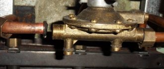
- Using a wrench, unscrew the nuts that secure the thermocouple to the solenoid valve, then you need to remove one of the ends of the thermocouple.
- Inspect the connectors. If they contain various contaminants or oxidation, they must be cleaned. For this you will need fine-grained sandpaper.
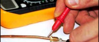
- Check the thermocouple sensor using a multimeter. To do this, attach one of the metal ends of the device to the multimeter, and heat the other with a lighter or torch. The multimeter reading should be within 50 mV.
- After that, if the indicator matches the data, you need to collect it in the same sequence. If not, then most likely it will have to be replaced.
If the thermocouple is in order, then the cause of the breakdown may lie in a malfunction of the solenoid valve. Clean the contacts that connect the two devices, then you need to check the operation of the sensor.
Replacing the thermocouple in the oven of a kitchen gas stove is carried out differently. First you need to remove the lid of the gas stove; it is located on the opposite side from where the oven tap handle is located.
Gas control repair manual
If the gas on the stove goes out, then the problem may lie not only in the thermocouple. However, most often this is precisely the problem.
The main sign of problems with gas control is that after igniting the burner and releasing the handle or button to open the “blue fuel”, the flame immediately goes out. This occurs due to the valve closing, since the thermo-EMF to keep it open is absent or insufficient.
The reasons for the noise of gas stove burners are described in detail in the article, the useful information of which is worth reading.
You should independently check, repair and replace the thermocouple in a gas stove with your own hands only when the gas is completely shut off. First you need to close the valve on the cylinder with the gas mixture or the methane pipe, and only then begin any work. Also, do not forget about turning off the power supply if the design contains volatile devices.
The thermocouple tip is located directly next to the burner and gas fire. And in the oven you can find it near the flame divider in the upper part of the oven. This tip should be free of carbon deposits, mineral deposits and any damage.
If the working tip of the thermocouple sensor is covered with scale, it must be cleaned off with sandpaper. The more carbon deposits, the less heat reaches the thermocouple, and the less it accordingly creates an EMF. The resulting millivolts may simply not be enough to open the solenoid valve.
How to check before replacing?
The thermocouple usually has one tip for installation near the fire. But there are also options with two or three temperature control tips. They are usually used in ovens, but it all depends on the specific model of the stove.
Thermocouples with several working tips have a peculiarity - if only one of them is not heated or fails, the solenoid valve will be closed. Therefore, in order to accurately find the cause of the problems, such thermocouple devices will have to be checked especially carefully. Only one of the sensors may be faulty.
Another point is that the thermocouple conductors in the area up to the valve must be tensioned or dangling in the body of the plate. At the same time, their connection to the electromagnet must be rigid; a connector hanging “on my word of honor” is unacceptable here.
The devices in question are produced with lengths from 40 to 130 cm. You should choose a thermocouple gas monitoring device based on this indicator very carefully. On the one hand, the conductor wire should not be over-tensioned, and on the other hand, it should not lie on heated surfaces or dangle freely.
How to change the device?
Before replacing a damaged thermocouple in a gas stove, you should inspect the device for:
- the presence of carbon deposits on the working tip (if there is any, it must be cleaned off with sandpaper);
- no burnout of this tip (in this case, only complete replacement);
- the rigidity of the connection between the contacts of the thermocouple sensor and the valve (if necessary, tighten);
- serviceability of the thermocouple itself with the output of an EMF at a level of at least 15 mV when heating.
The device in question should only be replaced when it is definitely faulty. In many cases, to get a gas stove to work again, you can get by by cleaning the tip from carbon deposits and checking the contacts.
The working tip of the thermocouple is rigidly fixed near the burner or burner using a nut. If it cannot be unscrewed due to scale, then you should not put too much pressure on the key. This can only break the fastening. It is better to use a solvent first.
The second end of the thermocouple is attached to the solenoid valve using a threaded connector or two crimp contacts. Removing them doesn't seem difficult. The new thermocouple sensor is installed in a similar sequence - one end of it is attached near the burner, and the other to the electromagnet.
How can I check it?
Keeping your home safe is a working thermocouple sensor. Several times a year, the thermocouple requires mandatory checks and adjustments. To do this, invite a specialist who will perform a safe and accurate analysis of the device.
When checking thermocouple readings, consider the measurement quality of the device itself by systematically checking its operation.
Reasons for incorrect operation of the thermocouple:
- incorrect soldering of two metal rods;
- presence of electrical noise;
- you smell gas, there is a leak;
- thermoelectricity is inhomogeneous.
To resolve these issues, during device installation you should:
- choose a thermocouple with thick and large wire;
- avoid temperature changes;
- do not allow tension and vibration of the metal wire;
- use a sensor that has a working temperature spread.
You need to check the serviceability of the thermocouple by following the step-by-step instructions.
- The thermocouple has two ends. When checking, one of them must be heated with a flame from the igniter, and the second must be secured to the thread of the valve (electromagnetic) using a nut.
- The next step is to separate it from the boiler. Then you need to ensure a stable flame. A gas burner is also used for this purpose. But experts advise using a candle flame.
- The tip of the device is immersed in the flame, it should be approximately 1 cm above the flame. Here you need to remember that the fire heats the device to almost half, so it is better to hold it by the tip.
- Next, a tester is used that determines millivolts. It is connected to the output contact and to the body of the thermocouple itself.
- If the thermocouple is working properly, then 30 seconds after heating the result will be from 17 to 25 mV. But if this indicator does not exceed the minimum threshold, then this means that it is faulty.
You can find out more about how to replace a thermocouple on a gas stove.
The thermocouple for a gas boiler is a thermoelectric converter for automatic control and monitoring systems of gas equipment. The device serves as the main element of gas control protection and is designed to ensure the fastest possible shutdown of the gas supply in the event the flame goes out.
Comments
I especially liked “try to revive your gas control or “kill” it completely by turning the stove into a USSR device that works just fine without gas control”
- Login to reply
Either no one is reading this, or one of two things. Interesting article. It's a pity, it's hard to read... The font is small and blurry. And in the pictures the text (in the explanatory frames) is completely unreadable. Apparently the material was ripped off from somewhere and copied poorly. I'd like to see the original.
- Login to reply
reset your @ . I'll send it to you by email. article. if there is the same effect, I will correct it, I am the “aftar” of this creation. I don't do plagiarism. ). poked around personally..
- Login to reply
It is not clear why the quality was lost. The original Word document looks flawless.
- Login to reply
- Login to reply
Good afternoon. I wanted to get an opinion or get advice from experts. The valve “stopped” working: I checked the thermocouple separately - it produces 40 mV from a regular burner; I checked the valve - it works exactly starting from 700 mV (dead AAA battery). I don’t understand what the problem is yet, because... It seems like the emf of the thermocouple is within normal limits (I’m very surprised by the reading of your thermocouple. Maybe there’s a problem there.). Because the valve operates from external power, I wanted to know whether the winding on the valve will not be covered when used in this way?
- Login to reply
Good afternoon, I don’t know the indicators of the thermocouple, because... it failed, but the valve was triggered somewhere around 1V, “pulled” 400mA. My entire “kitchen” in the post, when powered by an external power supply, is relevant as a temporary solution to the problem during the period of purchasing (purchasing) a valve or thermocouple, or a kit in general. If you don’t think about buying them, unscrew the valve, remove the rubber gasket, remove the spring - the headache will disappear. ) The stove will turn into the USSR - a device. )Good luck.
- Login to reply
PS. Try repairing the contact connections by removing the thermocouple, cleaning the seat, etc. connections between the terminal and the housing. It seems to me that your thermocouple is bad. Don’t worry about the valve winding. Increase the voltage until the valve operates - it will not take extra current.
- Login to reply
Thank you for such a quick response! I have already cleaned the thermocouple contacts as much as possible, but, alas, or fortunately, there was nothing to clean there except carbon deposits. I have already taken measurements on a test bench without unnecessary details. Considering the gluttony of the valve, it also seems to me that the problem is in the thermocouple, but in contrast to this there is a table of TEDS of standard thermocouples (https://kipiya.ru/2008/04/04/tablica-termo-eds-standartnyx-termopar/, https:/ /temperatures.ru/pages/graduirovochnye_tablicy), where the maximum readings do not exceed 70 mV. That is why I began to look for help, because at the moment I have two impressions: the valve winding has deteriorated since it requires so much to hold and the thermocouple has deteriorated since it produces so little. But neither of these stand up to criticism. Or am I missing something. In general, there are two options left: either remove the valve or buy a kit. For now, I’ll just bypass the thermocouple using external power.
- Login to reply
in terms of standards - the table focuses on industrial thermocouples, low-current (USSR-CIS standards), as for gas control - these thermocouples are “tailored” for bourgeois stoves. In fact, industrial thermocouples produce a LOW-CURRENT SIGNAL to electronic devices (with further amplification thereof) for control thermal processes. As for the t/p gas control, it (it was specially developed for the valve) produces a significant current to the valve, and the valve needs to overcome the resistance of the spring and also press down the gasket. In production there are hardening transformers (soldering of cutters). They produce 2 volts from the step-down winding between the contacts. The cutter is clamped and heated. The current is 400 - 600A. Approximately the gas control thermocouple is rated for a current of up to 500mA. Gas control cuts off the gas from the oven faucets, burners... It won’t go anywhere else until you open the faucet. If you look at the comments on the Internet about gas control, you can conclude that it is not perfect and is short-lived. = flush cistern with electronics unit. ) They install it to “make money” (IMHO). and there are no spare parts. There is a place for do-it-yourselfers to practice.
The design and principle of operation of a thermocouple in a gas boiler
The thermocouple consists of two conductors made of different types of metal, resistant to maximum temperatures, which are connected in a ring. One of the soldering points is installed in the measurement area, the second is connected to the converter device. The physical phenomenon in the form of the thermoelectric effect (Seebeck effect) forms the basis of the operating principle of the thermocouple:
- two elements from different metal bases are firmly connected at one point. The difference in the composition of the conductors is a fundamental factor in the operation of the device;
- when the junction is placed in an open fire, a potential difference appears at the other ends of the soldered conductor.
What does a thermocouple look like for a gas boiler?
Next, a voltmeter is connected to the cold ends of the device, the circuit is closed and the measuring device shows the voltage.
How does a flame sensor work in a gas boiler?
A flame ionization sensor is a device that is designed to ensure the safe operation of gas boiler equipment. The device monitors the presence of fire, and if it detects a lack of flame, it automatically turns off the boiler. The operating principle of the gas boiler flame sensor provides the following:
- the functionality is based on the formation of ions and electrons when the flame is ignited. The formation of an ionic current causes the process of attracting ions to the ionization electrode. The device is connected to a combustion control sensor;
- If, when checking with a combustion control sensor, the formation of a sufficient level of ions is detected, this means that the boiler is operating normally. If the ion level decreases, the sensor blocks the operation of the boiler equipment.
The key reasons for the operation of the ionization sensor include contamination of the valve and incorrect gas-air level ratio. This also happens when a large amount of dust settles on the ignition device.
Water leaks
Inside the flow-through heater, water tubes are connected to various components using union nuts and rubber O-rings. Homeowners who have not maintained their units for years may find water dripping under the unit. If this is discovered, then repairing the gas water heater consists of checking all connections and replacing the seals.
There are other places where water can leak, for example, through the operating rod of the water unit. This suggests that, at a minimum, the seal on the frog rod needs to be replaced, which will require its removal and disassembly. In models equipped with a safety valve, the latter may also leak, especially if it has been released several times. Finally, the most unpleasant situation is a damaged heat exchanger in which a fistula has formed. Buying a new one is very expensive; it’s easier to repair the old one, which is discussed in the next section.
Main types of thermocouples for a gas boiler
In the manufacture of thermoelectric converters, alloys of noble and base metals are used. For specific operating temperature ranges, certain groups of alloys are used. Depending on the metal pairs used in manufacturing, devices are divided into several types. The following types of devices are most often used to operate boiler equipment using gas fuel:
- thermocouple type E. Factory marking ТХКн, consists of plates made of chromel and constantan. The device is designed for a temperature range from 0°C to +600°C;
- type J. Provides a composition of iron and constantan, TFA marking. Used for operating temperatures ranging from -100°C to +1200°C;
- type K with TXA marking, made on the basis of plates of chromel and alumel. The temperature range of application of the K-type thermocouple is significant – from -200°C to +1350°C;
- type L with THC marking. The structural elements are chromel and copel. The device is designed for temperatures from -200°C to +850°C.
Thermocouple for gas boiler type J
The following product samples are used in heavy industry:
- type S with TPP10 marking is a platinum-rhodium-platinum composition. Used in installations at temperatures up to +1700°C;
- type B with TPR marking consists of a composition of platinum-rhodium-platinum-rhodium plates. The product is intended for the temperature range from -100°C to +1800°C.
Other versions of similar devices are also manufactured from precious metal alloys, which are relevant in heavy industry and foundries.
Types of temperature sensors for gas
Thermocouples of gas stoves differ in the alloy of conductors and the type of connection to the valve. And the main thing here is that each manufacturer of gas-powered equipment uses its own versions of electromagnets with different connection connectors.
In most cases, it is impossible to move the thermocouple gas control sensor from one tile to another.
The following alloys and metals are used to create thermocouples:
- constantan + chromel;
- copper + constantan;
- copper+copel;
- nisil + nichrosil;
- alumel+chromel;
- constantan+iron;
- chromel+copel;
- platinum+platinum;
- tungsten+rhenium.
The accuracy of the device and its operating temperature range depend on the alloys used. For example, a chromel-alumel thermocouple is designed to operate at 0–1100 0 C, an iron-constant thermocouple at 0–700 0 C, and a platinum-platinum-rhodium thermocouple can withstand heating up to +1700 0 C.
Household gas stoves usually use thermocouple sensors made of alumel and chromel or constantan and iron. They are inexpensive and quite suitable for the temperature conditions of a gas cooktop.
Thermocouple in a gas control system
When operating gas equipment, non-volatile automation is required, which helps to quickly shut off the gas supply in case the flame suddenly goes out. Modern heating boilers with a gas burner are equipped with a gas control system, which includes an electromagnetic valve and a thermocouple. The components of the electrovalve include:
- core with winding;
- cap;
- return spring;
- anchor;
- rubber band blocking the gas supply.
When you press the gas supply button, the rod is buried inside the coil and the spring is charged. According to the regulations, the supply valve should be held for about 30 seconds so that the thermocouple warms up and voltage is generated at the ends to hold the valve inside the coil. The thermocouple begins to cool if the burner goes out. What happens next:
- this is accompanied by a decrease in voltage at the ends of the thermocouple;
- the return force of the spring exceeds the electromagnetic force that holds the rod inside the coil;
- the valve returns to its original position and the gas supply is shut off.
This is the job of a thermocouple in a gas boiler. The gas control system based on a thermocouple is highly reliable, including due to the fact that it can function without being connected to the power grid.
Free electricity with your own hands (video)
Getting free electricity is not as difficult as it seems. Thanks to various types of generators that work with different sources, it is no longer scary to be left without light during a power outage. A little skill and you already have your own mini-station for generating electricity.
- Device, principle of operation and main types
- Thermocouple in the gas control system (gas control)
- Connection, testing and troubleshooting
The use of gas for heating a private house or cottage is very convenient and cost-effective. However, this type of fuel poses a serious threat. If for any reason the burner suddenly goes out and the gas supply is not turned off in time, a leak will form and this can result in serious trouble and endanger the lives of people in the room. In order to immediately shut off the gas if the flame suddenly goes out, a thermocouple is used for a gas boiler.
In this article we will talk about what a thermocouple is, why it is needed and how it works, we will consider the main types and most common faults associated with these devices, as well as methods for eliminating them.
Connection nuances and verification
Connect the thermoelectric converter to the measuring device using a compensation cable. In order to minimize the measurement error as much as possible, the cores of this wire are made of the same material as the sensor itself.
Check the functionality of the thermocouple as follows:
- one end of the device is connected to a multimeter;
- the other end is manually heated using a lighter or gas torch.
To check the functionality of the thermocouple, connect one end of the device to a multimeter
If the device is in good condition, this is indicated by the presence of a voltage in the region of 50 mV.
Possible malfunctions and methods for eliminating them
If, when you press the gas supply button, the burner turns on and immediately goes out, this indicates a malfunction of the thermocouple. It may also be the result of poor contact between the converter and the solenoid valve.
Repairing a gas boiler thermocouple malfunction is as follows:
- remove the end of the thermocouple by unscrewing the clamping nut with a wrench, with which the transducer is attached to the valve;
- if upon inspection the presence of contaminants or oxides is detected, clean the contact area with fine sandpaper;
- Next, use a multimeter to check the functionality of the device.
If the valve is in working condition, it is necessary to ensure the correct connection of the converter to the valve: find the appropriate position of the clamping nut for optimal contact.
You should know that if the gas boiler converter fails, the device cannot be restored. Here it is necessary to replace the thermocouple by installing a new sample in its place. Products in this category are offered by many domestic and foreign manufacturers, including Arbat, Zhukovsky AOGV plant, Honeywell concern and other industrial companies. The price range for this device varies between 600-2000 rubles.
The main areas of application of thermocouples are automation of gas equipment, foundry industry installations and many other areas of production. Based on this device, a whole range of thermostats and thermometers for household and industrial use has been developed. In the hands of folk craftsmen, a thermoelectric converter can become the basis for a mini power station; it is used to create chargers with which you can charge low-power devices from an open fire, including from a fire.
From this article you will learn what problems can arise in the automation of gas boilers, why it is impossible to ignite the igniter, which is why the boiler can turn off for no reason, and most importantly, we will figure out what actions need to be taken to diagnose and eliminate this malfunction.
Owners of non-volatile gas boilers are probably familiar with the situation when, for some reason, it is not possible to ignite the boiler, or a lot of time is spent on ignition. In this case, the problem lies in the boiler automation.
Today, the gas valve EUROSIT 630 is most often used in domestic and imported gas equipment. It is this valve that performs the function of maintaining the set coolant temperature and, in the event of an emergency, completely shuts off the gas supply to the burners. Further starting of boilers with such automation is only possible manually. However, the cause of a boiler emergency shutdown is not always a real accident.
Let's try to understand this using the example of the Zhitomir-3 boiler. Automatically, it provides protection against loss of flame on the igniter and loss of traction.
Note: All gas-hazardous work must be carried out exclusively by representatives of specialized organizations that have the appropriate permits. Therefore, this article is provided for informational purposes only. This article will also help you monitor the work of the technician and, perhaps, save you from the need to purchase unnecessary spare parts.
Let's decide what we will call igniting the igniter. The EUROSIT 630 valve control knob allows you to switch the boiler to three main modes:
- disabled;
- ignition;
- temperature adjustment (1–7).
To ignite the pilot burner (igniter), you must move the control knob to the “ignition” (spark) position, press it and use the piezo ignition button to ignite the pilot burner. Next, the handle is held for several seconds (no more than 30) and released. The pilot light should continue to burn. This is what we will call igniting the igniter. If the pilot light goes out, you need to repeat the procedure several more times. If this does not help, you need to look for the problem.
At the moment the igniter is ignited, the flame heats the thermocouple, which in turn generates an EMF (approximately 25 mV for working SIT thermocouples), which is supplied through the automation sensor(s) circuit to the solenoid valve.
Options for installing TSP-N and KTSP-N on pipelines:
Installation type A: For pipelines with a diameter of up to 25 mm, temperature sensors of a special design KTSP-N version 6 (type DS-cable) (TSP-N version 6) with a short immersed part and installed in the corresponding fittings - expanders, which are included in delivery kits for heat meters and flow meters.
Installation type B : In pipelines with a nominal diameter of no more than DN 50 according to GOST R EN 1434-2, installation of temperature sensors in a bend (in an elbow) is also allowed. Temperature sensors on the measuring sections of pipelines can be installed both before and after the flow converters.
Installation type C : If perpendicular (radial installation) of temperature sensors is not possible, then they can be installed obliquely, at an obtuse angle (from 120 to 150 °) to the direction of flow. Moreover, the angles of inclination of the longitudinal axes of the temperature sensors included in the kit to the direction of flow on the supply and return pipelines should differ by no more than three degrees.
Installation type D : For resistance thermometers, perpendicular (radial) installation is the most preferred.
In heat meters, in accordance with the requirements of the Rules for metering thermal energy and coolant on the supply pipeline, resistance thermometers are installed in front of the flow converters, and the distance between them and the flow sensors must be at least 3 DN, and the distance from the resistance thermometers to the nearest local resistance upstream ( including mechanical and magnetic filters) must be at least 5 DN. And if the local resistance is a group of elbows in different planes, a manifold for merging flows, sharp expansions or contractions, or fittings of any type that regulate the flow of the medium, then the distance from such local resistance to the resistance thermometer upstream should be more than 10 D.
To reduce the length of straight sections in front of the temperature sensor after local resistances that cause significant swirling of the flow, flow shapers should be used.
FOR THE AUTHOR'S CERTIFICATE (1)911102
Union Soviet to
Resnubpik. (61) Additional to auto. said-vu (2) Declared 040779 (2>) 2789973/22-02 (5!) M. Cl. with the addition of application No. 2999393 f 22-02
USSR and affairs of theories and discoveries (23) Priority
Published 070382. Bulletin No. 9 (53) UIC 536.532 (088. Date of publication of the description 070382
Yu.V. Malkov, A.S. Kozhevnikov, A. Romanovskaya, G.A. Kadyshev and A.G. Zayev
Cherepovets Order of Lenin Metallurgical Plant named after. 50th anniversary of the USSR
I (72) Authors of the invention (7l) Applicant (4) METHOD OF INSTALLING THERMOCOUPLES
The invention relates to temperature measurement, mainly in heating furnaces with double-sided heating.
There is a known method of installing thermocouples for measuring the temperature of the medium in heating furnaces containing lower and upper zones and a system of heating devices. Thermocouples are located in the upper zones in the roof and in the lower zones in the side wall of the furnace.
With the indicated arrangement of thermocouples in the lower zones of the furnace, the temperature of the environment near the side masonry of the furnace is recorded, and it is impossible to obtain a reliable temperature measurement in the volume of the zone, especially on furnaces with a hearth width of more than 6 m due to the large size of the zone (15.
The disadvantage of the known method of installing thermocouples in a heating furnace with walking beams is that thermocouples for measuring the temperature of the medium in the lower zones, located in the masonry of the side walls on the side of the burners, do not provide accurate measurement of the temperature of the medium and, therefore, high-quality regulation of the temperature regime in the zones due to their low sensitivity to changes in gas temperature in the volume of the zone when fuel consumption changes. This is explained by the direct influence on the thermocouple of the torch of the nearest burner and the cooling effect of the air entering the working space of the furnace along the periphery of the burner. Besides,. with such installation of thermocouples in the lower zones and a staggered arrangement of metal/on support beams, the temperature level of the upper zones influences the side thermocouples installed in adjacent lower zones.
Due to the indicated shortcomings in automatic temperature control. temperature in the furnace is underheating
3 and overheating of the metal, which requires switching to manual control of the furnace.
The purpose of the invention is to increase the accuracy of measuring the temperature of the medium and to ensure control of the required temperature difference along the length of the slab.
This goal is achieved by the fact that according to the method of installing thermocouples in the heating furnace in the upper and lower zones of preliminary and final heating of the furnace, thermocouples are enclosed in lined thermoblocks and installed in the lower zones of preliminary and final heating on the hearth along the axis of the furnace, 15 at In this case, the thermocouple junction is located (at the level of 0.3-0.8 of the height of the lower zone.
In addition, thermocouples in the final heating zone are placed across the furnace at a distance equal to
3.5-7.54 from the width of the hearth relative to the axis of the furnace, and the working junctions isolate them from each other.
The thermocouple junctions are located at a level of 0.3-0.8 of the height of the lower zone. This is due to the fact that at a height less than 0.3 of the height of the lower zone, the thermocouple reading is affected by the temperature of the hearth masonry. At a height of more than 0.8 times the height of the lower zone, the reading of thermocouples is affected by the heated metal. To obtain uniform heating of the slabs along the length, thermocouples for measuring the temperature of the medium in the lower heating zones of the furnace are located on the hearth along the axis of the furnace. This eliminates the influence of the burner torch and the air entering along the periphery of the burners on the thermocouple readings, and the thermocouple measures the average temperature in the furnace zones.
To ensure a given temperature difference along the length of the slab in the zone
i$ final heating independent temperature measurement simultaneously at two points along the width of the furnace and the possibility of separate regulation of different temperature conditions according to
S0 width of the furnace thermocouples are located on the hearth at a distance from each other equal to 7-15 from the width of the furnace hearth, and their working junctions are separated from each other by a refractory partition and facing in opposite directions in the opposite direction.
55 instructions for installing appropriate side heating devices. Side partition eliminates exposure
4 per burner thermocouple. the opposite side. If the thermocouples in this chamber are installed at a distance,. greater than 15 times the width of the hearth, the thermocouple falls into the area of influence of the burner torch.
When thermocouples are located at a distance less than 7/5 of the width of the furnace bottom, the temperature of the medium is measured not in the corresponding zone along the width of the furnace, but some average temperature of two zones, which eliminates the possibility of heating the slab with a given temperature difference along the length.
In fig. Figure 1 shows a heating furnace with installation of thermocouples, longitudinal section; in fig. 2 - the same, cross section; in fig. 3 - a thermocouple enclosed in a thermoblock for monitoring and regulating the temperature of the medium in the lower heating zones. oven areas; in fig. 4 - thermocouples enclosed in a thermoblock, separated by a partition, to control and regulate the temperature in the final heating zone.
The method is carried out as follows.
Along the width of the furnace 1 (Fig. 1 and 2) there are several movable 2 and fixed 3 (Fig. 2) longitudinal support beams. Heated slabs 4 and 5 are located on fixed beams, perpendicular to them. Transportation of slabs into the furnaces is carried out using movable (walking) beams 2.
When the furnace operates with automatic thermal control, the metal, moving from the landing window 6 to the final heating zones Vll u V!!I, is evenly heated in the heating zones !-H! to the set temperature. Uniform heating of the metal is ensured by combustion of fuel in fuel-burning devices
7 installed in the lower zones. lV, Ch and Vl in the side walls, and reliable indicators of thermocouples
8, regulating the change in heat. THOUGH STATE OF THE ZONES. The reliability of the readings of the thermal state of the zones is achieved by installing thermocouples on the bottom along the axis of the furnace, their perception of the average heat flow of gases moving through the center of the furnace, and eliminating the influence of individual fuel-burning devices on the thermocouple readings 7, 5 91
When metal arrives in eons
Vll-Vill final heating, the permissible temperature difference along the length of the heated slab is achieved by supplying different amounts of fuel to the left 9 and right 10 parts of the zone and independent temperature measurements of the left and right parts of the thermal zone. pairs 11 installed on the bottom of the furnace and separated from each other by a refractory partition 12, eliminating interference between the left 9 and the right
10 parts of the zone. This allows you to automatically maintain a given level of temperature difference along the length of the slab.
When heating slabs 5 with their staggered arrangement on the support beams, the influence of the temperature level of the upper zones l, lll, V u Vll on the readings of thermocouples 8 and 11 of the lower zones is eliminated, since the latter, “located on the hearth, are constantly blocked from the upper zones by the slabs. Consequently, placing thermocouples in the lower zones of the furnace bottom increases the measurement accuracy, allows you to obtain the required quality of heating of the slabs, and automatically control the heat. mode and in the lower zones, as well as improve the economic performance of the furnace.
1. The method of installing thermocouples in a heating furnace in the upper and lower zones of preliminary and final heating of the furnace, which means that, in order to increase the accuracy of temperature measurement on calls, thermocouples are enclosed
The invention relates to the field of electric heating, namely electrical installations of conveyor-type radiation heating, and can be used in industry for heat treatment of objects of various physical natures
The thermocouple is the main control and measuring module in non-volatile gas boilers. If it malfunctions, it is impossible to supply gas to the burner, it will not be possible to ignite the boiler, and attempts to bypass its operation are simply unsafe. Fortunately, the design of the thermocouple and the algorithm for replacing it are quite simple; with minimal skills, you can fix the problem yourself, in some cases even without replacing the module.
Read in the article


