Shut-off valves are designed to protect against accidents and tragedies. If there is any suspicion of a leak, the gas valve is first turned off, and then repair work is carried out. However, it is not always possible to sense the increased gas concentration in the room in a timely manner. Solenoid valves (or solenoid valves) were developed for such cases.
In this article we will analyze the design and operating principle of the solenoid valve, consider what types exist, and also study the requirements for installing these devices.
Setting a gepard or panther gas boiler to a power below the minimum
At the third stage, the minimum boiler power is adjusted to a value lower than specified in the instructions.
Such adjustment is not necessary in all cases, but only when the first and second stages do not bring the required result. As in our case, when at the first stage we use the “-” button to set a new boiler power value = 9 (the minimum possible setting corresponds to 8.5 kW).
It should be noted that adjusting the boiler power using the method described below is also useful in other cases, since it allows, through an experiment, to adjust the heating power of the boiler in accordance with the actual power of the heating circuit. The actual power is usually less than the calculated one.
Before carrying out work on setting the minimum burner power, you must:
- Fully open thermostatic and other valves on radiators and set the room thermostat to maximum temperature. The thermostat that controls the heated floors is set to the maximum permissible temperature so as not to overheat the floors.
- In the custom menu of the boiler, set the maximum operating temperature, which is set by the owners in the coldest weather, adding another 5 °C. Usually this is not less than 65 °C. If the owners do not remember it, or on a new boiler, set the factory setting of the maximum temperature of 75 ° C in the menu. The boiler burner will have to automatically turn off at a temperature 5 °C higher, i.e. at 80 °C.
- Cool the heating circuit to a heating water temperature below 30 °C.
Next, we start the burner in heating mode, select line d.52 in the service menu, press the “mode” button and see on the display the value of the gas valve stepper motor position parameter in the factory minimum power mode.
By removing the front cover of the boiler, we visually observe the size of the flame in the burner. In our example, the factory setting was displayed on the display, the number = 72, and the flame height in the burner was quite high.
Using the “-” button we set a new parameter value in line d.52, for example =20. 3 seconds after the change, when the new value is automatically confirmed, we observe a significant decrease in the flame height in the burner. This indicates that the useful power of the boiler with the specified setting will be greatly reduced.
Next, observe on the display the increase in temperature in the direct heating pipeline at the outlet of the boiler. Typically, the temperature increase stops when it reaches a value less than the set value, for example 52 °C. The boiler is running, but the temperature does not increase (or changes very, very slowly). This means that a power balance has been achieved between the boiler and the heating system at this established water temperature.
At this moment, we increase the parameter in line d.52 of the service menu, set a new value = 30 - the temperature begins to rise again and stops again, for example at 63 ° C. Again we add the parameter value in line d.52 =35 and so select the parameter until the temperature stops at a value slightly higher than the maximum, for example 77 °C.
Number of moves
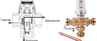
The most common are two- and three-way valves. Four-way ones also exist, but they are used extremely rarely in everyday life. Two-way valves are “locking”, that is, with their help you can limit the flow of coolant (water), while leaving the boiler performance at the same level.
Three-way valves are divided into separating and mixing valves. As is clear from the name, separation valves distribute the coolant into two streams. Mixing valves, on the contrary, mix the flows, and by adjusting the valve, you can achieve the required temperature in the system.
Purpose and device
This type of gas valve can be regulating or shut-off and can be controlled manually or using an automatic system. In design and purpose, this element resembles its standard counterpart, with the difference that the locking part in it is driven by an electromagnet, supplemented by a movable core. When voltage is applied to the coil, it begins to push or pull in the core, which is connected to the rod. This part is intended for use in industrial installations, domestic heating systems and in the water supply sector. The valve device has a standard design:
The housing for installation is made of non-magnetic metal alloys or durable plastic. Its optimal tightness allows the valve to be used in a variety of environments. The process of controlling the part is carried out via wires that are connected to the electrical contacts of the sensor located on the outside of the housing.
Scope of application
Household and industrial devices
The standard solenoid gas valve has a wide range of applications and can be used in all areas where there is a need to control remote flows of liquids and gases. This list includes heating systems, water treatment and water supply, irrigation and sewerage systems, household appliances, and pipeline transport. The device is rarely used for vehicles, but its relevance is increasing in other industries.
How does a gas valve work?
Most gas units have a SIT valve. It includes the following elements:
- gas pressure measuring port at the valve outlet;
- adjusting screw for minimum and adjusting nut for maximum fuel consumption;
- lid;
- inlet pressure measuring port.
The gas boiler valve consists of a shut-off and modulation coil. When a voltage of 220 V is applied to the shut-off valve, a minimum volume of gas is supplied to the burner in accordance with the factory settings. The voltage is then transferred to the modulation coil. The processor, depending on the operating mode (power), supplies voltage with different modulation frequencies, regulating the amount of gas passing per unit time.
To set the boiler gas valve to minimum power, you will need a differential pressure gauge, a wrench and a screwdriver. The setup process includes the following steps:
- Remove the protective cap covering the differential valve screws.
- Open the fitting to measure the gas pressure supplied to the burner - turn the locking screw 1.5-2 turns counterclockwise.
- Connect the pressure gauge hose to the inlet fitting.
- Turn on the heating mode and disconnect one wire of the modulation coil - this is necessary so that the valve supplies gas to the burner to a minimum, which will correspond to the minimum power of the unit.
- According to the pressure gauge readings, set the minimum gas pressure on the burner. To do this, rotate the internal screw located under the protective cap. At the same time, fix the outer nut.
The dynamic fuel pressure at the gas valve inlet ranges from 1.4 to 2.4 kPa. If measurements show that the pressure is outside the specified limits, it is necessary to call gas specialists.
In the factory power range, there is no need to manually reset the gas valve. This is required in order to transfer the unit to a power lower or higher than the values stated in the instructions. Often, valve adjustment is needed if the performance of the device does not correspond to the heated area of the house or apartment.
Why the gas boiler turns off - reasons and methods for solving problems
How to connect a thermostat to a gas boiler?
Setting the gas valve when the boiler is “clocked”
A problem such as “clocking” of a gas boiler can be solved by adjusting the gas valve. It usually occurs if the power of the unit significantly exceeds that required for a given area.
To prevent the device from “clocking” in heating mode, it is necessary to reduce the outlet pressure. This is done by turning the adjusting screw counterclockwise.
To stop “clocking” in DHW mode, reduce the maximum pressure. This can be solved by rotating the adjusting nut counterclockwise.
However, in more modern models, “clocking” is eliminated automatically. For example, setting the gas valve of the Buderus boiler is done by blocking the cycles:
- hold the button with the wrench for 5 seconds;
- select the duration of intervals from 0 to 15 minutes using the arrow buttons.
It is recommended that adjustments of this kind be carried out only by service center specialists, especially if the boiler is under warranty. Otherwise, if you damage the valve, the company will void the warranty and you will have to buy a new part.
From the article you will understand the principles of adjusting pressure, thrust and power during operation of the device. Find out the probable causes of problems along with options for eliminating them. If you need to tune the boiler, use our materials. Do not forget about the safety rules, and you will successfully configure the device and fix minor problems.
You should be interested in the settings of a gas boiler long before purchasing, taking into account your needs and various features. We have written which parameters can or should be changed in the device you are using. The new device should be configured and prepared for operation, and some undesirable aspects can be corrected.
Wall unit electronics
A special feature of these heat generators is electronic control of the processes of ignition, combustion and maintenance of coolant temperature. That is, wall-mounted gas boilers (and some floor-standing ones) are equipped with energy-dependent automation powered by electricity.
Important point. Despite the many bells and whistles introduced into the design of mini-boiler houses, safety functions are still in charge of the mechanics. The three types of emergency situations listed above will be processed by the equipment regardless of the presence of voltage in the electrical network.
An automatic gas boiler was created for maximum convenience for owners of apartments and private houses. To start the heater, just press 1 button and set the desired temperature. Let us briefly describe the operating algorithm of the unit and the elements involved in it:
- After these startup steps, the heat generator controller collects sensor readings: coolant and air temperature, gas and water pressure in the system, and checks the presence of draft in the chimney.
- If everything is in order, the electronic board supplies voltage to the electromagnetic gas valve and at the same time a discharge to the ignition electrodes. The wick is missing.
- The main burner ignites and gives full power in order to heat the coolant as quickly as possible. Its operation is monitored by a special flame sensor. The controller includes a built-in circulation pump.
- When the coolant temperature approaches the set threshold, which is recorded by the overhead sensor, the combustion intensity will decrease. Staged burners switch to low power mode, and modulating burners smoothly reduce the fuel supply.
- Having reached the heating threshold, the electronics will shut off the gas. When the sensor detects cooling of the water in the system, automatic ignition and heating will be repeated.
Note. In turbocharged boilers with a closed combustion chamber, the controller also starts and turns off the fan.
The instructions for the wall-mounted gas boiler indicate that the unit is designed to operate in a closed heating system, so the automation monitors the water pressure. If it drops below the permissible limit (0.8-1 Bar), the burner will go out and will not light until the problem is corrected.
Many imported boilers operate according to an energy-dependent scheme, for example, Buderus Logano, Viessmann and so on. How the installation of electronic gas equipment occurs, the master will tell you in an accessible language in the video:
KSU-2P control kit.
The following modifications are available for boilers operating on gas fuel:
- KSU-2P-1-G (as part of control and signaling units BUS-1 and switching element unit BKE-1) - for boilers with natural circulation with vacuum;
- KSU-2P-2-G (as part of blocks BUS-2 and BKE-1) - for boilers with natural circulation with pressurization;
- KSU-2P-3-G (as part of blocks BUS-3 and BKE-2) - for direct-flow boilers with supercharging.
The supply voltage of the kit is a three-phase network 380/220 or 220/127 V with fluctuations ranging from +10 to -15%. The supply voltage is set using jumpers on the block located in the control and signaling unit (BUS). AC frequency 50 ± 1 Hz. Power consumption no more than 300 VA.
KSU-2P, together with sensors and actuators, provides: two-position regulation of the main technological parameters of the boiler (stabilization of the water level in the drum - for KSU-2P-1-G and KSU-2P-2-G; stabilization of steam pressure - for all modifications); safety automatics (gas supply to the boiler is stopped in case of emergency decrease and increase in gas pressure, decrease in air pressure, increase in steam pressure at the boiler outlet, absence of burner flame, emergency increase and decrease in the level in the boiler drum - for KSU-2P-1-G and KSU-2P-2-G, lowering the vacuum in the boiler furnace - for KSU-2P-1-G, in case of an emergency increase in the temperature of the steam at the boiler outlet and the temperature of the exhaust gases - for KSU-2P-3-G); light and sound alarms with storage of the root cause of the accident; issuing signals to the control panel about turning on the set and stopping the boiler; automatic start and stop; working alarm.
The BUS contains functional blocks. On the front panel of the BUS there are operational control and alarm controls (figure below). In addition, the BUS includes intermediate relays used to control the boiler actuators and magnetic starters of the BKE unit 16, as well as to switch the BUS circuits during the execution of the control program.
Let's consider the main advantages
- Efficient operation of the system on different types of gas supply.
- The system does not require connection to the electrical network.
- There is a starting gas filter and a special screw to regulate the fuel supply.
- Possibility of operation of the device at low gas pressure.
- Function to turn off the system when there is insufficient draft or when back smoke occurs.
- Stable temperature conditions.
- Possibility of smooth adjustment.
- Piezo ignition is modeled to make the device as simple and convenient as possible during operation.
- Constant outlet pressure.
- Simple design and compact dimensions of the device.
Installation of the device
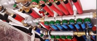
Installation diagram in an apartment
The valve is connected by specialists or independently if you have the appropriate skills and qualifications. First, the principle of connecting the part is determined, which can be threaded or flanged.
In the first case, the outlet and inlet pipes will be supplemented with external or internal threads and fittings through which the fittings are built into the pipeline; this method is considered more convenient for DIY installation.
In the second case, the pipes and pipe ends are supplemented with flanges bolted together. This option is most often used for lines with medium or high pressure. Before installation, you will need to mark, cut and clean the pipes, and also select a suitable location for the device. The device is connected in accordance with the directions of the arrows marked on its body, which indicate the direction of flow.
The pipeline system must be supplemented with a filter to prevent contaminants from entering. When connecting the valve, it is necessary to follow safety rules and recommendations of professionals.
Adjusting the power of a gas boiler
In this case, the task is to reduce or increase the indicator. The indirect method of adjustment involves reducing the supply through the taps: the one located after the supply to the boiler and the one on the downstream side. The range of regulation will decrease, so it is better to prefer direct methods.
To increase power, select an option:
- Adjust the burner to the desired level - relevant for modulating units.
- Buy a more efficient burner.
- Replace the injectors with larger ones. Remember, with an increase in heat transfer from the boiler, gas consumption will increase, the risk of breakdown ahead of schedule, and the efficiency will decrease.
Ideally, it is better to entrust the adjustment to increase power to a boiler specialist. The increase in power for these options reaches 15%. If this is not enough, use additional devices to heat the rooms. Remember to clean the boiler to maintain power levels.
Tubes with micro-torches for an atmospheric burner - such a device operates almost silently, but is characterized by low power, dries out the air in the room and depends on a large number of external factors
Sometimes you have to reduce power. First, it is adjusted through the menu: by parameters of the heat exchanger temperature and anti-cycling time. Then set up the circulation pump. If necessary, change the burner to a modulating one.
Reasons for changing boiler power:
- Increase: it is necessary to re-equip the device at the same time as increasing the power, connect an indirect heating boiler, the heating area has increased.
- Reduction: refusal of one of the functions (heating or hot water supply), part of the functionality (heating of individual rooms, heated floors), reduction in boiler performance.
If there is excessive fuel consumption, it is worth inspecting the secondary heat exchanger and removing residual salts manually or with a chemical compound. Contamination will be indicated by a characteristic gurgling sound when the boiler is operating.
Consumption increases due to the low specific heat of combustion (calorific value) of the gas. The norm is no less than 7,600 kcal m³. Poorly dried fuel's calorific value drops by almost half.
Also adjust the gas valve. They are regulated depending on the structure:
- single-stage ones have only “on” and “off” positions;
- two-stage valves are equipped with 1 inlet and 2 outlets, and they open in an intermediate position;
- three-stage boilers have two power levels;
- With the help of modeling valves, power can be adjusted more smoothly; they have many flame modes, in addition to the “on” and “off” positions.
Look at the color of the flame. If there is a noticeable yellow part, tighten the lower valve to reduce the fuel supply.
845 SIGMA Multi-Function Gas Valve with Power Modulation, Outlet Pressure Regulator and Fuel Control Module - Accommodates a variety of threads and flanges
Set the heating operating temperature on the thermostat again. The principle of its operation is that the rod is turned on. As the temperature drops, the element shrinks and opens the fuel supply. An increase in temperature leads to an increase in the rod, causing gas to flow in a smaller volume.
If there is a lack of air, inspect the damper, boost and temperature regulator. A popping sound when igniting the main burner appears due to clogged air supply paths. Remove dust from them and inlet openings.
Selection and configuration of equipment
The issues of operating the heat supply system of a private house, in contrast to centralized systems, fall entirely on its owners. And one of the problems that has to be solved is the issue of correct selection of gas equipment.
Experience in operating systems shows that a properly selected boiler should operate for at least 30% of the heating period.
The average value of boiler power consumption per square meter of a heated room (with a ceiling height of up to 3 meters) is about 100 watts.
Practice also shows that installing a boiler or burner with too high a power can create many problems associated with excessive gas consumption, difficulty in selecting the temperature in heated rooms and the reliability of the system.
After selecting and installing the heating system, as well as each time it is started, the following adjustments are made:
- Complete heating of the boiler.
- Full opening of the chimney damper.
- Setting the burner flame to maximum power (the flame should consist of blue and yellow segments).
- Shut off the gas supply valve when lowering to remove the yellow segment of the flame.
- Checking the safety automation and operating modes of the boiler.
Important! Setting the correct flame color of a gas burner is key to complete combustion of gas without the formation of soot that settles on the walls of the firebox and chimney, reducing the efficiency of the system and increasing gas fuel consumption
How to adjust burner power
If the burner significantly exceeds the boiler in power, it may not have enough firebox volume, air flow through the dampers and from the pressurization. In this case, the combustion of the flame becomes uncontrollable, and the burner flame turns yellow.
Incomplete combustion of gas fuel causes soot in the firebox and chimney with combustion products, and part of the energy is dissipated into the surrounding space, increasing fuel consumption.
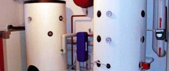
Photo 1. The shut-off valve helps regulate the gas supply in case of problems with the boiler.
In this case, the burner power can be reduced by closing the gas supply valve when lowering.
However, if the power is constantly set to the minimum value, this will reduce the efficiency and range of adjustments of the system.
Reference! When choosing a gas burner, in addition to the dimensions of the combustion chamber and the geometry of the torch, it is important to take into account the compliance of the passport values of the minimum and maximum power and methods of its regulation, as well as the gas consumption of the burner
High gas consumption
The reason for high gas consumption is often the ineffective operation of the boiler heat exchanger. The coolant passing through the heat exchanger carries with it particles of scale and salts, which can be deposited on the internal walls of the heat exchanger, reducing its thermal conductivity and increasing the amount of fuel required for heating.
Typically, a problem with the heat exchanger is manifested by a characteristic noise emanating from a working boiler, reminiscent of a whistling or gurgling sound, similar to a boiling kettle.
In this case, you will need to manually clean the heat exchanger or wash it with a special compound.
The reason for high gas consumption can also be its reduced calorie content, caused by insufficient drying by the gas distribution company. The norm of the lower calorific value of household gas should be at least 7600 kcal per cubic meter, but in practice the calorific value of gas can be reduced to 4000 kcal.
How and why to regulate the power of a gas boiler?
How to adjust the power of a gas boiler?
When setting up a single-circuit or double-circuit gas boiler, you can reduce or increase the power. By adjusting indirectly, you reduce it with taps.
You can increase power like this:
- Set the burner to the desired setting.
- Buy a new burner with higher performance.
- Change the injectors to those with a larger cross-section.
If you need to correctly reduce the power when setting up a gas boiler, then use the menu. Exchanger temperature and cycle time settings. And then they regulate the circulation pump.
Why you need to change the power of the equipment:
- Make it taller. The area of the room has become larger or there is a need to re-equip the device or connect a boiler.
- Do below. One heating, hot water or heated floor was turned off. There are fewer rooms. Boiler performance has dropped.
How to set the gas valve on the boiler?
How to set the gas valve on a boiler depends on the device:
- If the valve is from one stage, then it has an on and off switch.
- And when the valve is more complex in its design - 2 stages, then there will be an inlet and 2 outlets that open in between.
- With three stages there are 2 levels.
- When the valve is modeling, the power can be adjusted softly, adjusting the flame more accurately.
Set the degrees on the regulator. When the temperature drops, the element becomes small and gas flows well. And when the temperature rises, the rod is also larger and the gas flows less intensely.
If you see that there is not enough air, check the damper, regulator, boost. Popping noises during ignition may indicate that the air passages are clogged. It is worth removing dust from them and cleaning water holes.
Room thermostat saves gas
To automatically control the temperature in the house, boiler manufacturers recommend using a room or weather-compensated controller with a continuous principle of controlling the boiler flow temperature.
You can also use a room thermostat of a two-position principle (ON/OFF), but with less efficiency.
Boilers of luxury categories, as a rule, are immediately equipped with a remote control unit. Installed on the wall of the room, such a unit allows you to remotely control and monitor the operation of the boiler, and also serves as a room thermostat.
A room regulator allows you to maintain a constant temperature in a heated room with high accuracy. With manual control, the range of temperature fluctuations is larger and deviations are more often towards higher temperatures. Every extra degree in the room leads to an increase in gas consumption for heating. In addition, using a thermostat, you can program an automatic decrease in the temperature in the house during certain periods (at night...). Refusal of manual control of heating temperature and installation of an automatic regulator to maintain the required temperature in the room can significantly reduce gas consumption for heating.
In addition, to change the boiler settings, the owner does not have to run to the boiler room. Custom boiler settings can be changed right in the house, on the thermostat.
A room thermostat or room temperature sensor is always installed in the largest room of a house or apartment.
Room thermostat saves energy
When the boiler operates without a room thermostat, the circulation pump runs constantly, consuming electricity. The room thermostat controls not only the gas burner, but also the circulation pump. The circulation pump, controlled by the room thermostat, operates intermittently, which saves energy and the life of the pump.
Solenoid multivalve
In all these HBO systems, regardless of the class and principle of operation, a device such as a multivalve plays a key role. It is he who allows and blocks gas, filters the composition of the mixture, selecting harmful substances and impurities (which is why the built-in filter needs to be replaced regularly).
Removing scratches on a car body without painting.
DON'T SPEND MONEY ON REPAINTING! Now you can remove any scratch from the body of your car in just 5 seconds.
Read more >>
Initially, a conventional mechanical valve had only a shut-off function and was tightly welded directly to the cylinder. The first generation of vacuum-type equipment begins to use a valve with an additional vacuum membrane, which plays the role of a vacuum level sensor in the manifold. Further complexity of the design and general unification of cylinder necks from various manufacturers led to an increase in the number of simultaneously performed work operations. A modern electromagnetic multivalve for a car consists of a whole set of built-in valves connected by sensor feedback to an electronic control unit.
Thermocouple in the gas control system (gas control)
If you decide to install a solid fuel boiler in your country house, you do not need to worry about what will happen if the fire suddenly goes out. However, when you use gas equipment, you need non-volatile automation that can shut off the gas supply as quickly as possible if the burner suddenly goes out. For these purposes, modern gas boilers are equipped with a gas control system. How does it work?
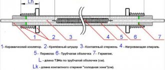
The system consists of two main parts: a solenoid valve and a thermocouple. One end of the sensor is placed directly in the burner flame, and the second is connected to an electric valve, which consists of a core with a winding, a cap, a return spring, an armature and a rubber band that shuts off the gas supply.
Photo 4: Non-volatile gas control system for stoves and boilers
The gas control works quite simply. By pressing the gas button, you push the rod inside the coil, charging the spring. According to the instructions for igniting a gas boiler, the supply valve must be held pressed for about several tens of seconds. This time is necessary for the thermocouple to warm up and sufficient voltage to appear at its ends to hold the valve inside the coil.
At the moment when the burner goes out, the thermocouple begins to cool, the voltage at the ends of the thermocouple decreases and at some point, the return force of the spring outweighs the electromagnetic force holding the rod inside and returns the valve to its original position, cutting off the gas supply. This process usually takes several tens of seconds.
Maintenance of Baxi gas boiler
Almost all gas boilers have the same design, regardless of the manufacturer. Through the heat exchanger, thermal energy from fuel combustion is transferred to the coolant. A gas boiler may have 1 or 2 heat exchangers. During operation, the heat removal surface becomes contaminated with soot, and scale forms inside the gas boiler. Due to these contaminants, the characteristics of thermal transfer are reduced, therefore, energy consumption will increase.
In order for the Baxi gas boiler to operate in economical mode, it is necessary to periodically carry out maintenance of the system
Particular attention should be paid to units with bithermal heat exchangers, which are difficult to clean due to their design
Principle of operation
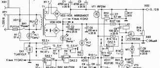
The operation of the device is based on the principle of electromagnetic instruction, when current flows through the coil, a magnetic field is formed inside it, affecting the core, depending on the position of which the gate element opens or closes. A valve for any gas pipe can have a different control voltage. Low level devices are low power, so they operate using low voltage semiconductor circuits. Such valves are used in systems with low pressure working media, on gas pipelines with a small diameter.
Drives operating on alternating current are considered more efficient, for this reason they can be installed on main pipelines with high pressure.
What is automation for a gas boiler
After the gas boiler starts up, control over its operation is entrusted to a specialized device, which begins to operate within the framework of the program embedded in it. One of the main points of using automation for gas boilers is to ensure the safe operation of the device. And also all models automatically regulate the maintenance of the required and preset heat temperature in the rooms.
According to their functionality, automation for gas boilers is divided as follows:
- devices that are volatile;
- devices in which control devices are volatile.
The first type uses models that require electrical energy, they have a fairly simple design and operate on the principle of residual power. A pulse signal is received from a sensor that controls the temperature, also called a temperature sensor, and a valve operating on an electromagnetic principle, following the instructions of such a signal, closes and opens, thereby either interrupting the gas supply or, conversely, provoking it.
The second type includes energy-dependent devices that operate based on the properties of the physically used substance, the one that circulates inside the circuit of the device itself.
Varieties
Gas valves for boilers are classified according to a number of criteria. The first of which is the number of inputs. Based on this indicator, the following types of valves are distinguished:
p, blockquote 7,0,0,0,0 —>
- Two-way. They are structures that have two openings - inlet and outlet. Their main use is to block the supply or open the flow of the working fluid of the pipeline.
- Three-way. Such mechanisms have one inlet and two outlets. Such valves perform shut-off, regulating and redirecting functions.
- Four-way. Such gas valves have four openings: three outlets, one inlet. In their operation, they are similar to three-way valves, only thanks to one more additional input, their scope of application is slightly expanded.