By giving preference to autonomous heating methods, homeowners want to solve the problem of heating an apartment or house once and for all. Independent heating not only provides optimal temperature conditions in residential premises, but also provides significant cost savings in the family budget. It’s up to you to decide which type of autonomous heating you prefer. First, let's get acquainted with the main existing home heating options, based on the energy they consume:
- Electrical devices.
- Solid fuel devices.
- Liquid fuel units.
- Gas appliances.
Each of the listed groups is divided into subgroups according to the installation method, the coolant used, the area of application, etc. But to this list of devices used as the main means of heating a home, it is necessary to add systems involved in the heating process as additional devices that increase comfort temperature conditions in the room. Such systems include so-called heated floors, electric and water.
Be sure to read: independent heating in the apartment.
Of particular interest in this regard is a water heated floor, operating from a gas boiler - an autonomous hot water generator. The system is relatively new, but has been sufficiently studied and is superior in efficiency to devices such as, for example, heated fans.
*
Types of heating equipment
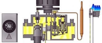
On the modern market you can find many floor-standing units equipped with 2 types of burners: atmospheric (characterized by quiet operation, simple design and affordable cost) and forced or turbo (have higher efficiency, but are noticeably more expensive).
Gas floor-standing boilers are also single-circuit and double-circuit, and can often operate without electricity.
Non-volatile units
Non-volatile boilers can be chosen for use in areas where power outages occur regularly. In order for such a floor-standing gas boiler to function normally, there is no need for access to electricity, but there must be a nearby gas main.
The coolant circulation here is based on a natural cycle, which excludes the use of a pump, which obliges the user to use pipes with a minimum slope.
The most modern models of floor-type gas heating units are equipped with a “smart” system for monitoring the functioning of the system, which includes a safety valve, pressure gauge and air vent.
Important! If there is a need not only for heating the room, but also for heating and circulating hot water, then it would be advisable to connect a boiler and pump to a non-volatile boiler. .
general information
A gas boiler is a device for heating water (coolant) using the combustion energy of natural gas or propane.
There are no specialized devices for heated floors, but there are models of boilers with the “warm floor” function , when turned on, the usual power limitation occurs, which is irrational.
A connection to a gas main or imported gas in cylinders is used, which significantly increases costs. Externally, a gas boiler looks like a small cabinet or wall cabinet; it usually has an attractive modern design (at least the new models). Thus, powering the heated floor in the house from the boiler is very convenient and efficient.
The design and principle of operation of heated floor heating
How to conduct heating in a private house with your own hands from a boiler
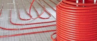
This floor is a structure made of small-diameter plastic pipes (cross-linked polyethylene or metal-plastic), which are characterized by high thermal conductivity, flexibility and low resistance. The length of pipelines ranges from 40 to 500 meters. They are manufactured as a single unit, which eliminates leakage at the joints.
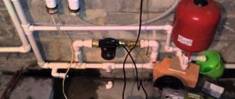
To maintain the required temperature, warm water floors are equipped with a coolant mixing unit, consisting of a collector, a pump and a thermostatic mixer with adjustable temperature sensors.
Warm floor heating can operate from two sources:
- Central heating systems:
- individual gas boiler.
It must be remembered that connecting such a floor to the central heating system in apartment buildings is strictly prohibited due to the increased load on the system and the possibility of water hammer. This can be done after agreement with the heating supply organization only in houses of new series, where a separate riser is provided for pumping out hot water in the event of a breakdown in the heating system. In this case, heat consumption meters must be installed.
Using the second method is preferable, since the coolant parameters are set individually and do not depend on the central heating system.
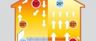
The operating principle of heated floor heating is quite simple: through a collector, using a pump, hot water under low pressure moves along the entire length of a specially laid pipeline. The floor covering, which has good thermal conductivity, heats up and releases heat into the room. At the same time, the air temperature near the floor is higher than at human height, which is physiologically justified.
Then, through the return line, the cooled coolant flows through the collector into the riser of the central heating system or into the gas boiler for heating.
Pipe laying
Selecting the correct pitch between turns of pipes and calculating the length of the pipes will allow you to correctly calculate the amount of heat distributed throughout the room. If you successfully calculate these parameters, then cost savings are guaranteed.
Requirements for rational use of the structure:
- The length of the liquid circuit is around 70 meters, preferably no more.
- Alternating cold and hot water flows leads to economical use of water.
- Determining the location of furniture where the floor does not need heating. Calculation of the pitch between turns of pipes and maintaining the distance when installing the system.
- After heating the pipes to the maximum level, the temperature is reduced by 20 degrees. This move allows you to save more while maintaining the desired room temperature.
- Elimination of improvisation and strict adherence to instructions.
Launch and operation
How to install a mixing unit for a heated floor with your own hands
After connecting all the elements, the level and tightness of the system is checked: the heating equipment is turned on and hot coolant flows inside, under a pressure higher than the working one (up to 0.6 MPa). The initial verification process lasts about half an hour, without reducing parameters. Then, within 2 hours, the pressure increases to 1 MPa under the same conditions of temperature and pressure stability.
If the system has held up, then you can start pouring the cement screed, and it should dry naturally. When a water heated floor is put into operation, complete heating occurs within a few days.
Tips and tricks
When wiring passes through a wall or other building structure, protection from mechanical damage is provided; for this purpose, a corrugated pedestal is used. In general, flexible pipes require care when connecting them to a “warm floor” heating system, especially polyethylene
They are carefully laid out according to the diagram, checking for damage: cracks, deformed (whitened) creases, deflections. Flexible heating lines are not removed from the coil in coils, but are sequentially unwound
When laying bends, adhere to a loop radius of 5 pipe diameters, and when installing fasteners, do not tighten the loops tightly.
An additional way to save money is to assemble a circuit without a pump, with the installation of a three-way valve-regulator (it independently mixes two different flows into one common one). If the water floor is connected not to the boiler, but to centralized heating, then the coolant cannot be used directly due to high pressure (8–12 times more than the installation instructions require). This is due to the risk of a break in the flexible line. The maximum effect from the operation of the boiler is achieved by simultaneous operation of both the heated floor and radiators (their connection does not differ from the usual one).
The recommended thickness of the top screed is at least 30–60 mm. Otherwise, the risk of damage to the pipes in the water floor increases. The practice of adding plasticizers to the solution has proven to work well. If tiles are used as a floor covering, then a top layer of cement of medium thickness (up to 50 mm) is poured, and the step in the wiring diagram is reduced to 10 cm. It is undesirable to put a substrate under the laminate, this will worsen the heat transfer performance.
Common mistakes when installing and connecting underfloor heating:
- Filling dry expanded clay over the pipeline (increases the risk of damage to flexible heating sections).
- Lack of a flat base, lower thermal insulation, or its layer is too thin. This leads to a decrease in the efficiency of the entire heating system.
- Use of ordinary metal pipes. Even in flat distribution areas, there is no point in laying material that is susceptible to corrosion in the floor.
- Deviation from the diagram, connection of a heating circuit with an area of more than 20 m2 or violation of the pitch. Leads to the appearance of “cold zones” on the floor and unreasonable energy consumption.
- Early start-up of the system, hasty filling of the coolant under pressure higher than the operating pressure, drying under heating conditions (contribute to the violation of the integrity of the floor and thermal deformation).
- Unreliable fastening of the edge tape (heat losses are possible).
Screed
IMPORTANT: the top layer of screed is poured only when the contour is filled. But before that, the metal pipes are grounded and covered with thick plastic film
This is an important condition to prevent corrosion due to electrochemical interactions of materials.
The issue of reinforcement can be solved in two ways. The first is to place a masonry mesh on top of the pipe. But with this option, cracks may appear due to shrinkage.
Another method is dispersed fiber reinforcement. When pouring water-heated floors, steel fiber is best suited. Added in an amount of 1 kg/m3 of solution, it will be evenly distributed throughout the entire volume and will qualitatively increase the strength of hardened concrete. Polypropylene fiber is much less suitable for the top layer of screed, because the strength characteristics of steel and polypropylene do not even compete with each other.
Install the beacons and mix the solution according to the above recipe. The thickness of the screed must be at least 4 cm above the surface of the pipe. Considering that the pipe ø is 16 mm, the total thickness will reach 6 cm. The maturation time of such a layer of cement screed is 1.5 months
IMPORTANT: It is unacceptable to speed up the process including floor heating! This is a complex chemical reaction of the formation of “cement stone”, which occurs in the presence of water. And heating will cause it to evaporate
You can speed up the maturation of the screed by including special additives in the recipe. Some of them cause complete hydration of cement within 7 days. And besides this, they significantly reduce shrinkage.
You can determine the readiness of the screed by placing a roll of toilet paper on the surface and covering it with a pan. If the ripening process is over, then in the morning the paper will be dry.
Kinds
Do-it-yourself installation of infrared heated floors under laminate
Home heating is divided into several types. This depends on a number of factors. For example, based on location, a warm water floor is divided into an option for a home and an apartment.
In fact, a warm water floor is often installed in a private house built from aerated concrete. Due to it, the house is heated evenly. In your home you do not depend on central heating; you have the opportunity to install a chimney and ventilation. This flooring is suitable for unpredictable climatic conditions in Russia, so it is common among summer residents who spend a lot of time in their country house. With such a floor, you can come there at any time of the year, rather than wait for a warm period, when the house can warm up on its own due to the air temperature around it.
In an apartment, problems may arise with the installation of water heated floors. Old houses are not suitable for this - the floor is uneven, the heating system is old, the management company is even more unlikely to take risks and will not agree to install the floor. In a new building, the situation may be different. Plus, you need written consent from the company servicing the house that the installation of such a floor is indeed permitted. Otherwise, you may receive a fine.
How to make a heat accumulator with your own hands
A do-it-yourself heat accumulator for a solid fuel boiler is an energy-efficient and simple design, representing a container in the middle of which there is a coolant that receives and stores energy. After the boiler has completed its operating cycle, the room is heated by absorbing the previously collected energy. Thanks to this, the heat accumulator significantly increases its efficiency and significantly saves resources.
Heating from a solid fuel boiler (installed by yourself) with a heat accumulator consists of many spiral tubes that are located around the entire perimeter of the container. This arrangement is explained by the fastest possible use of heat. Each of the spiral circuits located in the container is responsible for one action. For example, the first receives the generated thermal energy, the second heats the area of the room (building), the third heats water for domestic purposes.
Advantages of using a heat accumulator:
- Accumulation and concentration of thermal energy.
- Possibility of combining two or more heat sources.
- Increase in productivity.
- Availability of water heating.
- Temperature adjustment.
A solid fuel boiler with a water circuit, installed by yourself, allows you to save money when it is equipped with a heat accumulator.
To make your own heat accumulator for a boiler, you will need a large capacity. It is almost impossible to make it yourself. The ideal option is a stainless steel tank or any container with a lid. The thickness of the steel used is 4-9 mm. The preferred shape is a cylinder or sphere, in extreme cases a cube.
A suitable option is a barrel. For a cottage or country villa, the minimum barrel volume for a solid fuel boiler starts from 1 ton. On large containers, before using them, stiffening ribs are welded on, which will significantly strengthen them.
Having received the necessary container, think about its location, since in the future it will be much heavier. Next, diagrams and drawings will be needed.
Let's look at the step-by-step production of a heat accumulator for a solid fuel boiler. The procedure for its manufacture:
- A flange is welded to the size of the cover. In the future it will be used for bolted connections. To seal the lid, stiffeners are installed.
- The surface inside is treated with orthophosphoric acid (solution), primed 4 to 6 times and covered with two to three layers of high-temperature paint.
- Welding work is being carried out. Coils are welded inside the barrel.
- If possible, powder coating is done along with the coil. It allows you to obtain a high-quality coating, which increases anti-corrosion properties.
- The main tank and coil are checked for leaks.
- The outside of the barrel is being sanded and painted. The preferred paint is silver.
- Insulated with a layer of aluminum foil and a thick ball of min. cotton wool.
Safety requirements:
Considering that the heat accumulator for a solid fuel boiler is constantly heating up, fire safety rules must be observed
Anything that catches fire quickly and easily is moved to a safe distance. A closed type system will have a fairly high coolant pressure; accordingly, special attention should be paid to welds, joints, and connections. It is also necessary to install heat-resistant rubber gaskets on the lid that can withstand the operating temperature of the coolant. In the case of using heating elements for additional heating, it is necessary to comply with electrical safety rules: the tank must have an “earth”, that is, grounding, and the contacts must be insulated.
Their use is beneficial when:
- Needs for supplying hot water to large facilities (public baths, hospitals, kindergartens, schools).
- Use of fuel materials.
- The use of thermal compressors (makes their work more balanced).
As you can see, installing a solid fuel boiler with your own hands is a rather simple and primitive thing, but at the same time it has a number of features. The element is installed both in an apartment and in a private house. Installation costs are minimal, savings are maximum. The assortment is varied, everyone will find something that suits them. Also, it should be noted that you can make a solid fuel boiler with your own hands for the garage. If you are not confident in your own abilities, call a specialist, he will do all the necessary work efficiently and on time.
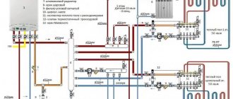
Collector diagram
The cabinet must be located in a room whose space provides free access for supply and return pipes. The side outlets of the manifold are connected to the ends of these elements to supply and receive heating fluid. Before performing the last step, it would be useful to install protective shut-off valves and temperature regulators in the system.
To simplify this entire procedure, many manufacturers began to produce ready-made valves that include not only the elements described above, but also shut-off valves for all outlets of underfloor heating pipes and radiators, which provide for disconnecting some circuits of the system when the main part of it remains turned on.
Valves, pipe ends and the manifold are connected using compression adapters - fittings that have completely different inlet and outlet sizes depending on consumer preferences. Often, the outlet pipes of a heated floor are connected to the collector using connectors that include a support sleeve, a ring with a clamp and a brass nut. The simplest connection consists of simple clamps with locking valves. The supply and return pipes are connected to the manifold, and it, in turn, is attached to the floor coolant outlets.
The named scheme is the simplest and will not be able to fully ensure proper control over the entire heating system, since it completely depends on the type of boiler (the only thing is that the shut-off valve can be closed a little to slightly reduce the supply of heating mass).
Choice
First of all, you should choose a water heater for underfloor heating of suitable power. Calculating the power of a boiler is a difficult task; the easiest way is to proceed from the average value - 1 kW of power per 10 sq. m. area.
It is necessary to pay attention to the possibility of adjusting the boiler operating mode. It is best if there is the possibility of smooth adjustment.
It is also necessary to decide on the required number of circuits, type of installation and other characteristics of the boiler, which will best meet the requirements of the existing premises.
Connection methods and installation features
Having considered what types of boilers there are, we can come to the conclusion that gas options are most suitable for connecting a warm water floor. Basically, the heating system is connected to a wall-mounted gas boiler.
If you want to connect the heating system with your own hands, then you will need:
- roulette;
- level;
- keys;
- screwdrivers;
- perforator;
- pipe cutter and other tools that will help in the work process.
When installing a warm water floor, the most important thing is laying the pipeline. Before this, you need to level the base using ties that protect the hot water pipe from various damages. The composition includes a sand-cement mortar, after hardening which forms a hard crust that protects the pipe. The pipe also acts as a battery with a large dispersion area. Expanded clay is best suited for insulation. You need to put a waterproofing film on top, as well as a reflector
The reflective material cuts off the heating circuit from the floor slab and the space underneath it. It must be of high quality so that the heat goes to the floor and heats the air in the room, and not vice versa. The pipes are laid in spirals directly on the reflector. The connection, in this case, comes from an already existing network, which is served by one boiler.
There are two options for attaching pipes:
- The first is using reinforcing mesh, to which the pipes are attached with wire.
- The second is with the help of fastening tapes and special clips, which can be purchased in specialized stores.
The length of the pipeline should not exceed 80-90 cm. A pipeline longer than one meter is not suitable for installation of such a structure. If this is not enough, you will have to add a new contour, taking into account that they must be the same.
The next stage is securing the pipeline to the supply manifold. Immediately after this, you can lay the contour. It must be laid in one piece to avoid leakage. The technology for installing heated floors includes checking the entire system. This stage consists in the fact that hot water, under pressure, is supplied to the pipeline. The test lasts approximately two hours. If everything is in order, you can lay the screed. Next, the boiler is installed. To do this, you need permission from the gas and fire departments.
Then you can connect all the pipes to the pipes with nuts or couplings. The boiler piping is done only with metal pipes. Afterwards, an expansion tank is installed to regulate the pressure in the circuit. Then comes the installation of the manifold - two pipe elements that are located one below the other. The number of pipes must match the number of circuits. The connection of the lower and upper sections of pipes is made using a bypass. A pressure gauge and an air vent are installed on the upper section of the pipe, and a tap is installed on the lower section to drain water from the pipeline.
The pump for underfloor heating can be installed anywhere, and the thermostat can be installed at a point that is not subject to drafts. After checking again whether the automation is connected correctly, you can make the first connection of the water floor. To do this, all circuits are filled with water and air is released. You need to check how the taps and valves work, and whether the connections are tight. To do this, several pressure control checks are done at intervals of one to two hours. During this time, it is allowed to reduce the pressure by only 20 kilopascals. If everything is in order, then you have coped with such labor-intensive work yourself.
Choosing the right boiler
The further microclimate in the rooms will depend on the gas boiler in the house. Often, such systems are chosen based on the cost benefits (outcomes) of one of the energy carriers. This approach, surprisingly, is the most correct one. When choosing a coolant, you should be guided by the following factors:
Boiler and heated floor
- The degree of complexity of the necessary installation work, which is aimed at installing complex equipment.
- Further degree of ease of use. The cost of its subsequent maintenance plays an important role.
- It is also worth considering the possibility of power outages and its complete shutdown in a particular region.
- Maximum and minimum system power.
- What is the most profitable energy source from an economic point of view?
The fact is that there is no company that produces heating boilers designed for heated floors. You can find models whose instructions contain information regarding its operation with heated water floor systems, but nothing more. The main distinguishing feature of floor circuits from radiator systems is the temperature of the main coolant. When using radiator systems, the coolant temperature can reach 80°C. The water floor pipes are only 55°C.
Boiler characteristics specification
In order to achieve an optimal indoor microclimate, the system must heat up to 40°C. The cooled coolant will have a temperature of 30°C. If radiators and heated floors are used for heating, which are supplied with heated coolant from the same boiler, then choosing a heat generator should not cause difficulties. Not every heat source can work to maintain the optimal temperature. To do this, you can additionally tie the unit.
Difficulties in connections may depend on the choice of one of the types of boiler and heated floor used:
- coal and automatic pellet;
- floor or wall gas;
- solid fuel;
- electric.
Boiler classification scheme
Specifications
Familiarization with the technical characteristics of a gas boiler allows you to quickly and fairly fully learn all its properties and capabilities.
Main indicators reflected in the technical characteristics of the device:
- boiler power;
- type of combustion chamber (open or closed);
- number of circuits (one or two);
- heating area (maximum, usually the upper limit of distribution is indicated);
- volume of fuel (gas) used;
- water consumption, ability to heat it. (2.5-17 l/min on average, there are also more productive models);
- Device efficiency (usually within 80-90%).
Water floor connection, mixing unit
When connecting a water floor to a boiler, a problem arises: different temperature conditions. If the coolant heats a regular boiler, and not a low-temperature one, then its output temperature is 70 o C-85 o C. Sometimes higher, sometimes lower, depending on the situation and boiler settings, but, in any case, the temperatures for a heated floor are unacceptable. Even taking into account the thermal inertia of the cement screed, it is impossible to apply more than 50 o C: this will threaten overheating. The most optimal option at the entrance to the water floor pipes is 40-45 o C.
How to connect a water floor to a boiler
The heated floor must be connected to the boiler in such a way that coolant at a lower temperature is supplied to the circuit. In a closed system, which is a heated floor, the temperature can only be lowered by mixing the cooled coolant from the “return” with the heated coolant. This is what the mixing unit or mixing unit does.
A schematic diagram for connecting a warm water floor can be depicted as follows:
If there are several underfloor heating circuits, a collector unit is installed (or assembled) after the mixing unit. This is a comb with several inputs and outputs (from 2 to 20), to which the heated floor circuits are connected. In the simplest version, this is a unit for parallel connection of underfloor heating loops.
In more “advanced” collector models, various devices are installed at each input. There are often bleed valves on the manifold to remove trapped air from the system. An air lock can block the movement of the coolant along the circuit, therefore the use of air vents is advisable.
In collector groups there are shut-off valves on each circuit. They can be controlled manually or using servomotors. Servomotors receive commands from automation, but such devices are already called collector groups or devices. They can also contain a mixing group and a circulation pump, and are then called collector stations. Naturally, the more complex and functional the device, the higher its cost.
This is what a connection diagram with a two-way valve might look like
You can save money if you wish. Assemble the mixing unit yourself and install a pump in the system. You can also make a collector group yourself, or you can buy a ready-made, but not very expensive, collector.
Mixing unit
Connection diagram for a water floor with a 2-way valve
The operation and capacity of the two-way valve is adjusted depending on the readings of the remote sensor. High-temperature coolant from the boiler is supplied through it. Cooled water flows from the return pipeline through the balancing valve. At the junction point the two streams mix. Coolant with a reduced temperature is pumped through a circulation pump and supplied to the collector. The temperature of the mixed flow is controlled by a sensor, adjusting the gap (and hot water supply) on the two-way valve.
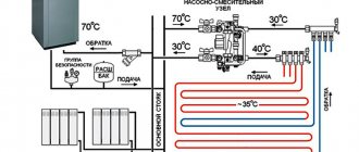
Detailed wiring diagram for a heated floor boiler (with a two-way valve)
To prevent backflow, you need to install two check valves on the “return”. As mentioned earlier, this scheme is good because the adjustment is smooth (due to the low throughput of the valve). In addition, in this scheme the addition of cold water is constant. And therefore the possibility of supplying only hot water from the boiler is excluded.
Water floor diagram with 3-way valve
The operation of the three-way valve can be controlled by a servomotor or an external temperature sensor (depending on the configuration you choose). The difference here is that the flows are mixed inside the valve, and the accuracy of maintaining the temperature depends on its operation. And this device has a large throughput, so that minor measurements in the position of the valves lead to quite sharp temperature changes. But when using weather-compensated automation and with large water floor contours, such a system is the only option.
Two options for mixing unit or mixing unit (click to enlarge size)
Connections of a water floor to a low-temperature boiler
If the temperature of the coolant at the boiler outlet can be set at your discretion (in systems without radiators), then the collector unit is connected directly to the boiler. This is the simplest option for connecting a water heated floor, but, unfortunately, not always possible.
What lies behind the technology
Such efficiency was achieved by providing the system with convection. The lower the installation level, the more evenly the surface of the floor covering will warm up. When connecting warm gas floors to the boiler, it is necessary to install an entire system of pipes under the floor. Additionally, a distribution manifold and circulation pump are installed. The collector is used when installing a heated water floor. Hot water enters the manifold from the boiler, after which it evenly fills all existing circuits. Passing through them, it heats the floor surface, and after cooling it returns back to the boiler.
General scheme
The system also needs to be equipped with additional control devices, such as:
- the thermostat is installed in any case, including under a heating boiler;
- a pressure gauge helps monitor the level of water in the system;
- check valves (their number depends on the level of complexity of the system and its size).
Connection diagram
Different contours will be needed for rooms of different sizes. The maximum system capacity and pipe length will have a number of design limitations. Compliance with the basic parameters when installing a water floor is more important than when installing an electric one. The cable will heat up evenly along its entire length, but over time the water passing along the circuit will cool down. One circuit is designed to heat a room whose area does not exceed 35 square meters.
The laying scheme depends directly on the size of the room. For large rooms it is better to use a spiral, while for small rooms it is recommended to use a snake. In rare cases, it is necessary to resort to a combination of schemes, but this issue should be dealt with by a professional. The pitch between turns can be from 15 to 25 cm. To complete the contour, you need to use only one pipe. It is recommended to use pipes made of metal-plastic. Such designs will bend well, be inexpensive and sold in bottles. If it is necessary to connect several individual elements within a circuit, then welding should be used. Couplings are suitable for mechanical connections, but they can only be used in open areas.
Laying scheme