A warm water floor can be connected to a heating system in many ways.
Let's look at four main schemes that are most often used in our realities. But before moving on to their detailed study, it is worth paying attention to the minimum requirements that generally apply to heated floors. They can influence the choice of scheme in one way or another.
Restrictions and regulations
Let's start with the fact that water heated floors do not belong to high-temperature heating systems. According to the standards, the coolant temperature cannot be exceeded or heated above 55C.
In practice, heating occurs to a maximum of 35 or 45 degrees.
However, do not confuse the temperature of the coolant and the temperature of the floor surface. It can range from 26 to 31 degrees maximum.
- where you are constantly (living room, bedroom, kitchen) - it’s 26C
- in rooms with temporary stay (bathroom, separate hallway, loggia) - 31C
Also, don't forget about the circulation pump. A warm floor is still a separate independent circuit. The pump can be either built into the boiler or mounted outside it.
With the help of a pump, it is easier to fulfill another requirement regarding temperature differences. For example, between supply and return, the difference should be no more than 10 degrees.
But when choosing a pump, do not overdo it with the flow rate of the coolant. The maximum permissible value here is 0.6 m/s.
Knowing all these limitations and recommendations, let's move on directly to the schemes themselves.
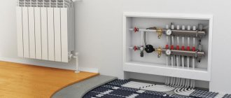
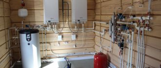
Manifold for underfloor heating system
For heated floors, a common collector unit is most often installed, or a separate collector is installed in front of each heating circuit. If the latter option is implemented, then all collectors are equipped with flow meters, thermostats, as well as the following elements:
- Return and supply mixing valve;
- Shut-off valve for balancing the heating device;
- Overflow valve.
You can assemble a collector for a heated floor yourself using different schemes, and in some schemes of collector units bypasses are used, but not always - only in single-circuit systems. If the underfloor heating system is organized according to a dual-circuit scheme, then the collector can be connected without a bypass to the secondary circuit.
Double-circuit underfloor heating system with collector
Before assembling a manifold assembly for a heated floor, weigh your options - sometimes it’s easier to buy a ready-made structure. If you are going to buy a collector, it is better that all its parts and elements are from the same manufacturer. When assembling the unit yourself, you must select the material from which the main components of the unit will be assembled: copper, steel, polymers or brass.
Also, when choosing an industrial design, it is important to consider the following parameters:
- How many heating circuits will there be in the system (usually from 2 to 12), the total length of the pipeline and the capacity of the circuits;
- Maximum permissible pressure in pipes;
- Possibility of expanding the heating system;
- Manual or automatic collector control;
- Electrical power of all components and assemblies;
- The diameter of the internal holes of the collector (throughput).
Do-it-yourself collector
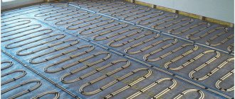
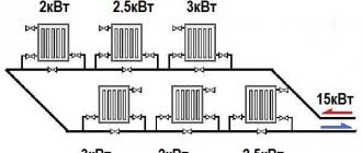
The most efficient operation of the assembled collector units can be ensured by connecting heating circuits of equal length to them. In order to equalize the length of the pipelines with sufficient accuracy, they are divided into equal sections, which are connected to the collector. The easiest way is to calculate the collector unit in a special computer program or on an online calculator, so that the phenomenon called “thermal zebra” does not appear, that is, uneven heating of the floor.
For the calculation you will need the following data:
- Type of decorative flooring;
- the area of the heated room and the plan for placing large objects in it;
- Material and diameter of circuit pipes;
- Boiler rated power;
- Type of floor insulation.
Reservoir calculation
Collector installation - recommendations
When designing a heated floor system, you first need to find the optimal location for installing the collector. Typically, the unit is installed in a manifold cabinet, and the cabinet itself is mounted at a height of 30-40 cm from the floor level next to the supply and return.
In order not to blame your own mistakes and ensure maximum heating of the heated floor pipes, study the instructions for connecting the collector. Then assemble the unit in the following sequence (this applies to an industrial manifold unit):
- Unpack the tubes for forward and reverse coolant supply. The tubes must have flow meters and supply valves. If the collector is multi-sectional, assemble the sections into one structure;
- From the assembled sections you need to assemble a unit on brackets (included in the kit);
- Next, we install shut-off valves, automation, sensors and other connecting fittings;
- We attach the unit to the wall or in a cabinet, install a thermostat, a servo drive and a circulation pump;
- We connect the pipes from the boiler and the pipes from the heating circuits of the “warm floor” system.
Manifold set
Now the connection diagram for the heated floor collector is pressed, after which the concrete screed can be poured. Thermal adjustments of the collector can be carried out after installation of the finishing coating.
DIY collector unit
A factory manifold is a fairly expensive product, so many craftsmen want to make it themselves. You will still have to buy many elements, but the cost will be cheaper. The easiest way is to solder a homemade manifold from PVC pipes and fittings Ø 25-32 mm. You will also need tees and bends of the same diameters, and shut-off valves.
Homemade collector
The number of valves and fittings is calculated by the number of heating circuits. The tools you need are a soldering iron for propylene elements and attachments for it, special scissors for cutting pipes and a tape measure.
Marking the collector consists of marking and cutting pipes of the required length, observing the minimum distance between the tees. Valves and transitions are soldered to the PVC tees with a soldering iron. Fittings for connecting the pump are soldered to this structure. As you can see, everything is simple, but it is better to buy more complex collector units ready-made.
Direct connection diagram
You have a boiler, after which all safety fittings + a circulation pump are installed. In some wall-mounted boiler versions, the pump is initially built into its body.
For floor-standing units you will have to install it separately. From this boiler, the water is first directed to the distribution manifold, and then disperses through the loops. After which, having completed the passage, it returns through the return line to the heat generator.
Specification of materials and equipment using the example of Valtec
With this scheme, the boiler is directly adjusted to the desired temperature of the TPs themselves. You don't have any additional radiators or radiators here.
What are the main features worth paying attention to here? Firstly, with such a direct connection, it is advisable to install a condensing boiler.
In such schemes, operation at relatively low temperatures is quite optimal for the condenser. In this mode it will achieve its highest efficiency.
If you use a regular gas boiler, you will soon say goodbye to your heat exchanger.
The second nuance concerns solid fuel boilers. When you have it installed, for direct connection to heated floors, you will also need a buffer tank.
It is needed to limit the temperature. It is very difficult to directly regulate the temperature with solid fuel boilers.
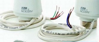
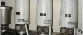
Outdoor temperature sensors
These devices are recommended for systems as automated adjustment of the coolant according to weather conditions. For example, if it is cold outside, a signal is sent to increase the temperature of the coolant. When warming is observed, the sensor tells the system that the temperature can be lowered.
The device is designed to rotate 90 degrees. A special controller divides them into 20 sections and monitors the conditions on the street. If the water temperature does not correspond to them, the valve turns the required number of divisions. Of course, you can do all this yourself, but it’s much more convenient with a weather temperature sensor.
Three-way valve circuit
In the vast majority of houses, this combined underfloor heating system is installed.
Specification of materials and equipment
It includes:
- presence of heating radiators with heating up to 70-80C
- separate TP circuit with an average water temperature of 40C
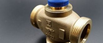
The main question here is how to get a flow of water for heated floors from the 80 degrees going to the batteries at half the temperature.
The problem is solved using a three-way thermostatic valve.
It is mounted on the supply pipe. At the same time, do not forget to install a circulation pump after it.
Colder water is taken from the return of the heated floor. Mixing with hot water coming from the boiler, the coolant acquires the lower temperature necessary for underfloor heating.
The disadvantage of this scheme is that you will not be able to accurately limit and regulate the flow of cooled water from the return. What does this mean?
The fact is that both water that is too cool and, vice versa, water that is overheated beyond normal will periodically enter the pipes of heated floors.
The efficiency and comfort of the entire system suffers because of this.
An unprincipled person may not notice this, however, these temperature differences are present in this circuit, and there is no escape from them. Of course, time periods of supply of hot and unheated coolant can be compensated by the thermal inertia of the screed concrete.
But this is all relative. You can never accurately calculate the optimal thickness with such heating.
The advantages of such a combined scheme with a three-way valve:
- easy installation
- affordable price of equipment
This installation method justifies itself if you have a small apartment or house. And you don’t suffer from excessive demands for super-comfortable living conditions.
Typical installation mistakes
Sometimes, when installing a warm water circuit, it is suggested to use central heating. These calculations are completely unacceptable, since the temperature in radiators significantly exceeds the required values for a floor heating system, and such a connection can cause serious damage to the pipeline. At the same time, in apartments without special permission, installation into a common heating system is prohibited.
Often, when installing water floor heating without a mixing unit, there are malfunctions in the operating process of the equipment or the system does not function effectively in the room. Such violations occur when certain errors are made during installation work:
- The installation was carried out on a fairly uneven surface. When installing the floor, differences not exceeding five millimeters are allowed.
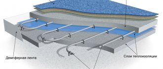
- Incorrectly selected foil insulation. For thermal insulation of the floor base, the best option is foamed polystyrene. After placing the material over the entire floor area, it is imperative to fasten all joints with masking tape.
- Pump power does not match system size. To increase the productivity of the working process of a heated floor without a collector group, you should purchase high-power circulation devices.
- The screed of the heating system is not made in accordance with the necessary technical requirements. When pouring concrete, people sometimes avoid installing a damper tape. Such a defect often causes cracks to form in the cement coating, which leads to heat losses. Also, the reason for the destruction of the screed may be turning on the system earlier than required. After pouring the floor with mortar, you should wait at least thirty days for the concrete to completely harden.
When installed correctly, the heating system should heat at least 70 percent of the space in the room. Therefore, before installing the equipment, you should correctly perform all calculations and outline a laying diagram.
Installing a heated floor without a mixing unit has several main advantages - ease of installation and connection, as well as cost reduction due to the lack of additional equipment. But it should be taken into account that the efficiency of this scheme is several times lower than when using a collector. But if there are no special requirements for heating the room, then you can save significantly by installing water floor heating without a mixing system.
Scheme with pump-mixing unit
This scheme also applies to combined systems, when you have both radiators and heated floors at the same time.
However, here, instead of a 3-way valve, a more expensive pumping and mixing unit is used.
Specification of materials
In fact, the cooled return flow is also mixed into the main boiler feed here. But thanks to the balancing valve, cooled water can be mixed in in certain doses and given proportions.
This will ensure the precisely specified temperature of the coolant entering the TP tubes through the manifold.
This is the most effective and most comfortable scheme. The pumping and mixing unit itself can be assembled in various variations.
Depending on your needs and financial capabilities, the following components may be included:
Operating principle
The mixing unit for heated floors is designed to regulate the temperature of the coolant in the system of heating elements (pipes). This happens as follows:
- The heated coolant (water, antifreeze, oil, etc.) from the hot water boiler enters the heating system.
- Reaching the distribution manifold, it is stopped by a valve.
- If the coolant temperature does not exceed the maximum set values, the coolant continues to move through the system.
- If the permissible norm is exceeded, the thermostat opens the valve, and the hot coolant from the supply branch of the heating system is mixed with the already cooled return branch. Mixing occurs until an acceptable temperature is reached, after which the valve closes.