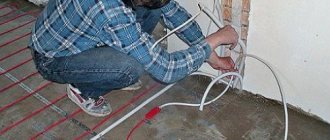
Any heating system installation technology involves heating that part of the room that is free from heavy objects. If the room is large (more than 40 sq.m.), then the diagram is divided into zones.
There are several options for laying water heated floor pipes. A properly installed heating system means the safety of residents, efficient heating of the room and peace of mind. There are several fundamental rules for installing a heating system:
- Heating elements are installed according to the manufacturer's recommendations.
- The equipment must fully comply with the power installed per 1 square meter.
- During installation, you must not change the pipe dimensions, laying steps, or stretch the heating elements.
- To avoid leakage, do not mechanically damage pipes, manifolds, or heating devices during installation.
- It is necessary to ground the cable in accordance with standards and PEU.
- To ensure uninterrupted operation of the system and the possibility of emergency shutdown, it is necessary to install a thermostat.
- It is forbidden to connect an unexpanded cable to the network.
- Installation is carried out at a temperature not lower than 5 degrees Celsius.
What is a heated floor?
This is one of the most popular heating systems in the world today. It has earned its popularity thanks to:
- Rational use of energy resources
- Uniform heating of the entire room
- Comfortable microclimate created during operation
- Durability and unpretentiousness
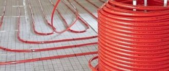
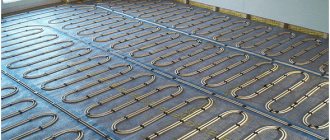
The system appeared relatively recently and has won the sympathy of many developers. It consists of pipes laid in a special way in a screed through which the heated coolant passes. This heat is then distributed throughout the entire room.
Calculate the length of the contour
When making calculations to determine the number of pipes for laying a structure - a water-heated floor, the following points should be taken into account:
- the total area of all premises;
- number of collectors;
- room layout;
- the size of window openings and doors through which heat can escape;
- wall thickness;
- placement of furniture;
- air humidity;
- purpose of the rooms;
- presence of other heating systems.
Based on the average, 1 m2 will require 5 linear meters of pipe, with a laying step of 20 cm.
To most accurately calculate the size of the pipeline, the following formula is suitable:
L = S/N x 1.1
Where:
- S is the area of the room;
- N—laying step;
- 1.1 - reserve for making turns.
To the data obtained, you should add the number of meters from the floor to the manifold cabinet and back.
For clarity, let's look at the calculation process using an example:
- room area - 15 meters;
- the maximum distance to the manifold cabinet from the floor is 4 meters;
- distance between pipes - 0.15 mm;
15: 0.15 x 1.1 + (4 x 2) = 118 meters
Another way to calculate the amount of pipeline is to reflect the laying diagram on graph paper. At the same time, it is necessary to observe the scale and take into account the size of the room.
After reflecting the entire system on paper, you need to measure the length of all the coils in the drawing using a ruler, and multiply this result by the appropriate scale.
Comparison of heated floors with radiators
If we compare the already familiar radiator heating system with a heated floor, then in the case of the first, hot air flows first rush upward when heated, and then only fall down. Therefore, with radiators, we quite often feel a cold floor.
The installed heated floor works on a different principle. The underfloor heating pipes first heat the screed, then the screed radiates heat evenly from bottom to top. The higher, the less intense heating.
Therefore, in terms of heat distribution, heated floors look much more advantageous. As for efficiency, both systems are the same, plus or minus.
They often like to mention that heated floors are more economical than other systems. This is a big misconception. The task of any heating system is to compensate for heat loss in the home. And heat loss is always constant. Therefore, resources must be spent equally. Warm floors can actually be much more economical. If you use advanced solutions for low-temperature systems.
Popular installation schemes
The heating installation consists of a coolant source, a collector, as well as copper and metal-plastic pipes. Each of the elements has features that are taken into account at the design stage. Therefore, the selection and purchase of the necessary products occurs with knowledge of what diameter the pipe has, etc.
In small residential premises, the source of coolant is an electric boiler, central water supply or solid fuel element. We list the main methods of laying pipes for a warm water floor.
Snake
Begin laying the contour along the wall. On the next surface, the contour follows a “snake” pattern, gradually filling the entire floor space. At the end there is a return to the hot water source. This option allows you to warm one half of the floor well with hot water, and the other with cooled water.
Double snake
It is carried out from the wall with a pipe folded in half, i.e. one half carries the hot coolant, and the other (on the opposite side) returns the cooled coolant to the source. The technique of laying the circuit allows you to heat the room as evenly as possible using two pipes with water (hot and cold). Thanks to double laying, the room warms up more efficiently.
Spiral
The technique is able to effectively and evenly heat the entire floor covering. The technique is most often used in rooms where constant floor heating is required.
It is worth considering that the area along the walls will warm up more intensely. However, the spiral circuit allows the use of lower power boilers. Laying the circuit using the spiral technique is somewhat more complicated than the “snake” technique, but thanks to the denser filling of the space, the required temperature in the room is achieved faster.
Double helix
A double helix (scroll) design is used to separate the zones. That is, one part of the room is heated more strongly. In practice, the double helix diagram looks like this:
- From the source of hot water, the pipe is laid in a spiral, but only in that part of the room where enhanced heating is required.
- The outlet from the first coil leads into the second, which covers the rest of the room and exits back to the hot water source.
So one selected part of the room is heated several times more than the second. This scheme is relevant, for example, for children's rooms with play areas on the floor in a specific part of the room.
Features of heated floors
Unlike other heating systems, underfloor heating has a number of its own features:
- This is a low temperature heating system. The serving temperature usually does not exceed 45-50 degrees
- The correct heated floor is not felt by your feet, since the surface temperature is only 28 degrees.
- Warm floors require a height of 14 cm (minimum with a finished coating). This must be taken into account when designing a house.
- The underfloor heating pipes are not leaking. Unless, of course, you deliberately buy cheap material or constantly apply high temperature and high pressure to the pipes
What parameters does the pipe pitch depend on?
Many people wonder at what step it is more rational and efficient to lay a warm water floor. This parameter affects the load power. It implies stable heating of the entire room. The contour pitch directly depends on the diameter of the pipe used (16, 20, 25 mm). Range – from 100 to 500 mm. The most popular steps are 150, 300 or 400 mm.
For example, the most effective step in a heating system with a power of 50 W/sq.m is 300 mm. Pipe pitch 16 for a warm water floor is relevant for rooms that require particularly strong heating on an ongoing basis. For example, in those areas where heat loss is greater (along the outer wall, near the door, etc.), the optimal pitch is 200 mm. Accordingly, with a power of 80 W/sq.m, it is recommended to reduce the laying step of the water heated floor (up to 150 mm).
The easiest contour laying technique to perform is a spiral. The pipes are laid with a 90 degree bend. In the “snake” technology, the bend is 180 degrees. This point complicates the installation of the heating system a little. If the room is large or has zoning features, then double schemes are used.
Important! The circuit must be laid from a solid pipe without overlaps or damage.
The optimal pipe pitch for a warm water floor is determined during system calculations and design. If the step is too large, a person’s sensitivity increases and the difference in the temperature difference of the floor covering becomes noticeable.
It is unacceptable to use a small pitch for pipes with a large diameter and vice versa. Such errors in the installation of the heating system lead to overheating of the circuit or thermal failures. This contributes to the disruption of the heated floor as a unified and effective system.
Important! To increase the efficiency of the system, each time increasing the distance between the pipes, the water temperature increases.
In addition to the size of the circuit, the step is influenced by the type and dimensions of the room, as well as calculations of the thermal load. With a load of 50 W/sq.m, the most rational distance between pipes will be 300 mm. With a load of 80 W/sq.m – 150 mm. The latter option is optimal for the bathroom, where the temperature of the floor covering is most important at any time of the year.
In addition to the constant step technique, there is a variable option for laying the contour. The essence is a more dense arrangement of pipes in a specific area. Typically, this technology is used near external walls, windows and doors. These zones are characterized by large heat losses. A rapid step is 60-65% of the standard one. The most effective distance: 150 or 200 mm for a pipe size of 20 or 22 mm. The number of rows is determined during the installation process.
Variable or mixed distances between circuits are practiced in non-primary premises, where there is no urgent need for constant heating, as well as in places with large heat losses.
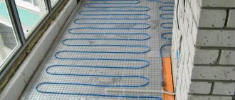
Before laying the contour, prepare the surface. To do this, it is necessary to ensure its uniformity. An error of 3 cm is permissible. The presence of bumps, dips and irregularities leads to the fact that after starting the heating system, the heating of the room will occur unevenly. A damper tape is laid along the walls of the room. It will reduce the risk of cracks when the screed dries.
Also at the preparation stage, thermal insulation is laid. Its density remains within 35 kg/cub.m. The last preparatory stage is laying the reinforcing mesh. It will serve as the basis for mounting the circuit and will help distribute heat more evenly. It is recommended to use special panels for laying pipes for water floors, which greatly facilitate the installation process.
Types of pipelines for a water system
Currently, the consumer market offers several options for materials and components for water heating systems. When choosing a pipeline for a heated floor, you need to take into account their cost, characteristics and service life.
Let's look at the most common types of pipelines and their characteristics.
Polypropylene
In a building materials store you can find two options for polypropylene pipes, such as metal-polymer and polymer. They are characterized by good resistance to corrosion, resistance to the abrasive action of the coolant and a durable top layer that does not deform when in contact with cement mortar. Manufacturers of metal-plastic pipelines guarantee that they will last about 40 - 45 years, polymer products - more than 50 years.
Polyethylene
A distinctive feature of these pipes is that no components are needed for installation. The joining of products is carried out using a soldering iron. To make the pipeline elastic, it will be enough to warm it with a hairdryer. Polyethylene products are reliable and durable, but for a water floor they must have a reinforcing layer. The average lifespan of a pipeline is 50 years.
Stainless
Corrugated pipes made of this material are considered the most durable; their service life has not yet been established. They do not corrode, do not deform from high temperatures and do not freeze during frosts. The flexibility of the material allows the pipeline to be laid in increments of different sizes, which simplifies installation work. The only drawback of stainless pipes is that their rubber seals have a service life of only 30 years.
Copper
According to consumer reviews, pipes made of this material have the highest heat transfer. You can use coolants such as antifreeze or antifreeze with them. They are easy to use. Due to its optimal size, the strength of the concrete screed is not reduced during installation. Their service life is about 60 years.
In addition to the above characteristics, when choosing pipes for laying heated floors, you need to pay attention to their technical parameters. They must meet the following requirements:
- Linear expansion no more than 0.055 mm/mK;
- Thermal conductivity is no less than 0.43 W/mK;
- Diameter – from 1.6 cm to 2 cm.
It is also worth paying attention to their purpose. Many beginners make a big mistake by choosing conventional hot water pipes for heated floors. Therefore, before purchasing, it is very important to read the attached instructions, where you can make sure that the product is suitable for the heating system.
Eventually
In conclusion, we can say that every technical nuance and parameter is important for the accuracy of calculations. Before you start purchasing equipment and consumables, make some simple calculations. This can be done manually, on your own, or using an electronic calculator.
It is important for yourself to learn a simple truth: what kind of heated floor do you need, as the main heating system or as an auxiliary means of heating
Take into account the power of the heat source, the area of the premises, and the required temperature parameters. All of the above data and other technological parameters will help you obtain ready-made calculation data with high accuracy, which you can rely on when installing heated floors at home.
Briefly about the main thing
What step to lay the pipe on the heated floor must be decided individually, taking into account both the characteristics of the materials and the initial data - heat loss in the building, depending on the thickness of the walls, the size of the windows and climatic conditions, personal ideas about a comfortable temperature. The amount of heat released to the floor surface will be influenced by the diameter of the pipes, their total length and the material from which they are made. And also the thickness of the screed, the type of flooring and even what the pipes are filled with. Therefore, calculations are made separately not only for each house, but also for each room in it.
Minimum distance between welds
The distance between welds in metal structures is determined under different conditions. Below are basic examples with distance restrictions.
| Type of seams and objects near which they are located | Determining the minimum distance |
| The distance between the axes of seams that are adjacent but do not interface with each other. | Not less than the nominal thickness of the parts being welded. If the wall is more than 8 mm, then the distance should be 10 cm and above. For minimum workpiece sizes, the distance should be at least 5 cm. |
| The distance from the rounding of the bottom of the workpiece to the axis of the butt weld. | What is taken into account here is not the exact dimensions, but the possibility of subsequently carrying out control using ultrasound. |
| Welded joints in boilers. | When located in boilers, welds should not reach the supports or come into contact with them. There is also no exact data here, but the distance should allow you to monitor the condition of the boiler during operation and not interfere with quality control. |
| Distance from holes to weld. | This includes welding or flaring holes. This distance should not exceed 0.9 of the diameter of the hole itself. |
| Distance from weld to insert. | Here, on average, a distance of about 5 cm is left. If we are talking about large diameters, then it can change upward. |
| The distance between adjacent seams at the holes. | The minimum distance should be 1.4 times the diameter. |
There are rules that allow seams to be placed at a shorter distance, which will be less than 0.9 of the diameter of the hole itself. This applies to cases where welding of fittings and pipes is planned. There are certain conditions for all this. For example, before boring holes, welded joints must be subjected to radiographic analysis. Ultrasonic testing can also be used instead. The allowance will be calculated at a distance of at least one square root of the diameter. It is necessary to make a preliminary calculation, which should show whether the product meets the specified strength parameters.
Minimum distance between pipeline welds
The minimum distance between the welds of the heating network pipeline is also regulated by certain documents. Taking into account the fact that repair of pipes and installation of pipelines using welding is more often carried out by specialists who work with critical structures, compliance with standards is more relevant here.
| Type of seams and objects near which they are located | Determining the minimum distance |
| Welding near transverse spiral, circular and longitudinal seams of any elements, with the exception of cathode leads. | Here you need to follow the rules very strictly, as this is strictly prohibited. Only if there are cathode leads provided for in the projects, the minimum distance between the seams should be at least 10 cm. |
| Distance between process pipeline welds. | It is calculated according to the wall thickness of the pipe itself. The minimum distance between seams for pipes with a wall thickness of up to 3 mm is 3 pipe wall thicknesses. If its size is above 3 mm, then a distance of two pipe wall thicknesses between the seams is allowed. |
| The distance of the seam from the bend of the pipe. | If you have to work with a pipe that has a bend, then the distance from the seam to the bend should be at least half the diameter of the pipe itself. |
Calculations of the pipeline itself are carried out in advance so that all bends, additional connections and other design nuances comply with accepted rules. During repairs, mistakes are often made and rules are not always followed, but this does not guarantee that the seam made will last long. After all, all tolerances for the distances between seams are taken based on the experience of previous work. The minimum distance between pipeline welds is determined according to GOST 32569-2013. All data regarding the operation, installation and repair of process pipelines is indicated here.
The final stage. Choice of flooring.
Ceramic tiles are considered the best option, since when they are heated, no harmful chemical processes occur. This option is ideal for bathrooms, toilets and kitchens. When choosing a coating for other rooms, the main thing is to choose a coating with special markings. Heated floor coverings are marked with a special sign.
Warm floor sign
Filling the screed
After the pipe is finished, you should start pouring the screed. It is better to use a “wet” screed, because it has the greatest heat transfer. The grade of concrete can be used m200-m300.
Before pouring the screed, we recommend laying a reinforcing mesh over the pipe for additional reinforcement.
Many manufacturers recommend pouring screed at least 5 cm from the top of the pipe. Often they pour 7-8 cm. If you pour in a smaller layer, you may have a “zebra” effect. This is when cold and warm areas on the final coating are clearly felt.
After the screed has been poured, heated floors cannot be used for 3 weeks. The screed should dry evenly. Afterwards you can fully use the water floor.
As a result, if you approach our instructions wisely, then heated floors with such a device will delight you in your home for decades. I hope this material was useful to you. Don't forget to check out the others too!
Do-it-yourself heating in a private house from polypropylene pipes
The main components of heating are a heat generator, pipes and heating devices. The rest of the equipment ensures the system operates under various loads. Equipping the system with additional elements depends on the size of the house and the modification of the selected boiler. The specified operating parameters of the unit are ensured by a safety group, an expansion tank with an overflow pipe, a supercharger and a pressure control device.
If the circulation pump is not built into the boiler circuit, then the blower is installed on the return line of the pipeline, in the immediate vicinity of the heat generator. The installation location of the closed type expansion tank for heating is in front of the circulation pump. The safety group is mounted on the supply line near the boiler.
Soldering polypropylene pipes with a soldering iron with your own hands
The concept of comfort is individual for each person. But for everyone, without exception, home is warmth. Heating is an integral part of any home. Maximum awareness of this topic will help you make an intelligent decision and implement it on your own.
Distance from the water supply to the foundation of buildings
If the water supply must be carried out in closed conditions, it is permissible to reduce the distance from the foundation to 1.5 m; a polymer pipeline is usually used; it is placed in a casing above the 0.5 m level of the foundation base.
When installing a water supply system, the following minimum tolerances are taken for foundation slabs and networks:
- architectural structures – 5 m;
- fences of industrial buildings, overpasses, supporting structures of contact electrical networks and communications, rail tracks - 3 m;
- railways with a gauge of 1520 mm not less than the depth of the trench to the base of the embankment and the edge of the excavation - 4 m;
- rail tracks with a gauge of 750 mm – 2.8 m;
- street curbs on the edge of roads or the side of the road - 2 m;
- ditch edge or bottom of the road embankment – 1 m;
- power transmission line supports: – with voltage up to 1 kV. (street lighting conductors, electrical contact lines of urban electric transport) – 1 m; – from 1 to 35 kV. – 2 m; – from 35 to 110 kW and more – 3 m.
- linings of deep cast iron tubes of the metro – 5 m;
- linings made of concrete materials placed below 20 m of the soil surface - 5 m.
- linings of subway structures without hydraulic insulation – 8 m.
The building codes indicate distances to the central axis of trees with a crown with a circumference of less than 5 m - in this case, the underground water supply system is laid at least 2 m from the axis.
Rice. 5 Standards for distances between underground utilities
Important installation details
PP pipes are connected using threaded/non-threaded fittings. In turn, threaded products can be:
- one-piece;
- detachable.
It is worth noting that installation is primarily affected by operating conditions.
- All polypropylene parts must be protected from fire.
- In the case of inserting a water meter or storage tank, it is advisable to use detachable threaded elements.
However, a permanent connection is acceptable only for flexible hoses. Water meter - The use of deformed or dirty connecting elements is strictly prohibited! Just like cutting threads yourself.
- When connecting flat sections or transitioning a pipeline to a different diameter, couplings are used.
- For turns, special angles are used; bending of pipes is unacceptable.
- Tees are used for branching the main line.