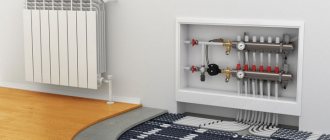
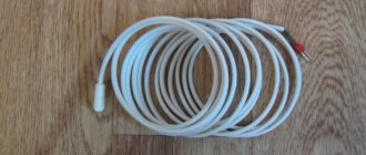
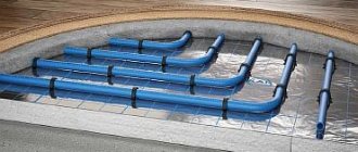
Warm water floors are gaining popularity today; they are a sign of comfort. But for such heating to function effectively, a pumping and mixing unit is required. It allows you to achieve the optimal temperature level of the coolant, as well as regulate its flow into the loops.
Therefore, we decided to talk about existing models of pumping and mixing units and their configuration. You will learn how to assemble a mixing unit for heated floors with your own hands, as well as how to install and configure it.
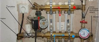
Pumping and mixing unit
Functions
The use of a thermo-mixing unit when installing a heated floor allows you to build an independent water heating system with the ability to adjust the temperature of the coolant.
Hydrofloor heating is a low-temperature equipment. Water should be supplied to the floor pipeline at a temperature of no more than +55 degrees. Since this structure is often connected to a battery or boiler, where the degree of heating of the liquid is much higher, a special mixing module is required.
It is in this unit that the cooled coolant from the return flow is mixed with hot water coming from the heating source to the required level.
This water mixing device also controls the volume of coolant flowing into each loop.
Separate requirements for gas equipment parameters
Heating using natural resources will have to be chosen correctly. Only in this case it is possible to avoid unnecessary negative emotions, waste of time, and loss of money.
All requirements are established by state standards. Their meaning is strict and unchanging. Linking directly to the area is due to technical capabilities. Which:
- 60 kW. Suitable for 2 meter ceilings. The room has 8 cubic meters of air volume;
- The boiler room is ventilated through three air exchanges. Combustion takes oxygen from a separate source. Kitchen window with window. The air flow is stable in both cases;
- There is a protective layer between the fasteners and the equipment itself. This is usually a sheet of metal. Its role is to prevent fire when the temperature rises during operation;
- the distance to the wall is at least 3 cm. The front side of the boiler allows it to be serviced on one square meter. From the sides, the distance from the unit is at least 60 cm;
- horizontal supply to the chimney no more than 3 meters. The diameter of the pipes used is the same as the heater. It's even better to connect a larger value. Then the hood is tougher.
Essentially, such requirements are checked by the company supplying gas to the house/building. It also allows the connection of such a device to a common highway. In the case of a gas holder, the owners of the premises check themselves. But it is worth remembering that their own lives are at stake.
There are no specific ones indicated for strapping. The gas boiler is connected to the floor heating system and then operates. Ensuring efficient work is compared with comfortable living conditions. An incorrect connection will affect the rest of the house.
The owners themselves are interested in proper connection by checking each parameter. It is better to place all aspects on the plan at the preparatory stage. Then it's easier to check.
We recommend: Is it possible to use underfloor heating as the main heating?
Principle of operation
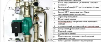
The essence of the functioning of any model of pumping and mixing device is the same. The flow of heated coolant, moving from the source, passes through a thermostat, where its temperature is recorded. Then the water enters the fuse, where its temperature level is regulated by opening and closing the head.
If the degree of heating of the coolant exceeds the specified value, then the fuse opens the damper and cooled water is added from the return line. When the desired degree is reached, the supply is blocked.
The pump is responsible for the circulation of fluid in the hydraulic system; the uniform heating of the floor surface depends on its operation.
Infrared radiometer
This type of pyrometer operates based on the radiation method and in a limited range of infrared radiation.
For ease of use, the device is equipped with a special laser pointer.
It helps to point the device at a specific place on the part and measure its temperature.
An infrared pyrometer consists of the following components:
- diaphragm;
- lens;
- copper casing;
- frame;
- lamp;
- light filter;
- eyepiece;
- heat;
- millivoltmeter
The operating principle of the device is based on capturing thermal radiation coming from a hot object and focusing it with a sensitive element connected to a thermocouple.
The device works like this:
The turned on pyrometer is aimed at the part being studied so that it is in the lens and completely blocks other objects from the human eye. The eyepiece moves and achieves maximum image clarity
It is important to use a filter. It will not only allow you to take measurements more accurately, but will also protect your eyes from the harmful effects of bright light. Thermal radiation reaches the sensitive element of the device
It is made in the form of a platinum plate. Thermocouples are soldered to it, which heat up depending on the temperature of the object. It is measured and the result is displayed on the device screen.
Areas of use
The need for a pumping and mixing unit arises if the coolant is water. Let's find out in what cases this happens.
- If the water heated floor is connected from central heating - since the heating of water in the centralized system exceeds the required level for underfloor heating.
- When connected from a boiler that does not operate with a return flow of +55 and below - these are all solid fuel boilers and those operating on gas.
- If the main line consists of two or more circuits with different temperatures (warm floors with radiators).
Selecting a thermostat
I would also like to touch upon the thermostat itself, which plays a very important key role in this heating system. There are the following types of temperature controllers for heated floors:
Electromechanical. The clarity of such adjustment is approximate, so achieving a specific set temperature is quite problematic.
The main advantage of such a device is its low price.
Electronic. Setting the desired value is done using touch buttons and has fairly clear settings and the ability to set the temperature limit down to one degree.
Programmable electronic. By installing such an element, you can not only regulate the temperature in the room, but also turn on the heating according to a schedule, or only when there is a person in the room.
By the way, some thermostats already have a built-in sensor, which makes it possible to control not only the temperature of the floor, but also the air in the room as a whole.
As a result, I would like to remind you about the rules for working with electrical equipment; all connection work is carried out with the power turned off.
At the same time, it is necessary to ensure that no one, except the person performing this work, accidentally supplies voltage dangerous to human health and life. This is where our technology for installing a heated floor temperature sensor with your own hands ends. We hope the information provided was useful to you!
DIY collector
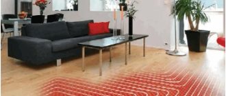
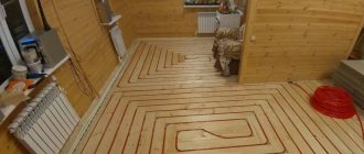
Warm floors have long been a sign of high-standard rooms.
Their use is due to the high quality of heating - the room is heated throughout the entire volume due to natural convection, since the entire floor area serves as a heater for the air in the room.
The floor itself is heated by an electric, film or good old water heater - a hot water boiler.
Kinds
All pumping and mixing units are divided according to the type of working body:
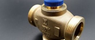
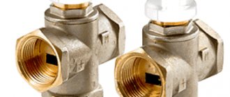
- With a three-way valve - installed in rooms with a large area, since the device is capable of passing a large volume of water. Such a tee for mixing is often connected to an external temperature sensor, which makes it possible to set the heating level based on the outside temperature. The adjustment process is carried out using a valve, which is located at the junction of the supply and return pipes. The design scheme generally used is sequential.
Three-way valve
- With two-way - recommended for rooms up to 200 m2, connected via both parallel and series mixing circuits. The valve has a thermal head with a sensor, it controls the temperature level, and if the indicator is exceeded, the hot water supply is shut off. The volume of liquid that this design is capable of passing through is small, so the adjustment process is smooth.
Two way valve
- Combined - combines a valve and a balancing unit. But this option is rarely used with heated floors.
Installation sequence
Let's move on directly to the installation of the heated floor and temperature sensor.
First you need to determine the location of the thermostat, which will be located outside. It is most often located at a height of about 1 meter from the floor. Its mounting is similar to a regular socket.
Then you need to make grooves or grooves for laying two plastic pipes.
One for the power wire leading to the heating element, the other for the electrical wiring of the sensor. The tube for the temperature sensor will be located on the floor. Such a gasket will make it possible to carry out repair work without removing the tiles, at least to replace control elements.
It is not possible to completely replace the heating element if it is installed in a screed. It is important that when laying a pipe or cable corrugation there are as few bends and turns as possible. This will simplify the replacement of a failed temperature sensor in the future.
The next step is thermal insulation, it is performed individually for different types of heating elements, for example, for a heating cable it is used as a damper tape or other insulation, the thickness of which is at least 1.5–2 cm.
After this, the heating element is installed and secured with wires being connected to the thermostat box.
Installing and connecting a heated floor temperature sensor has its own subtleties. In order to prevent solution from getting inside the tube where the sensor is located, its end on the floor is securely sealed with electrical tape or tape. It is not recommended to connect the entire system through an outlet; it is better to supply power from a circuit breaker and through a contactor (starter).
The temperature sensor should be installed at a distance of 0.5 to 1 meter from the wall on which the thermostat is installed, and also exactly in the middle between two adjacent turns of the heating cable. After installation, it is recommended to secure the temperature sensor with mounting tape or foil tape.
If a film heated floor is being laid, the temperature sensor must be installed under the heater sheet, as shown in the photo below. Please note that thermal insulation must be laid under the temperature sensor, otherwise the heating system will not be effective.
Important point! The location of the temperature sensor should be selected so that it is away from other heating sources. Otherwise, errors will occur and the warm floor will not work as it should.
The connection diagram for the heated floor temperature sensor is as follows:
Before making a screed, you need to check the functionality of the warm floor and the temperature sensor itself. As a rule, the resistance of both elements is measured. The system is considered operational if the resistance differs by no more than 10% from the passport data.
In order for the assembled circuit to be as safe as possible, it is recommended that in rooms where electric floor heating is carried out, protective shutdown devices are installed, which, in the event of a breakdown, will disconnect the circuit from the voltage, thereby protecting a person from falling under electrical potential. In damp areas this can be deadly.
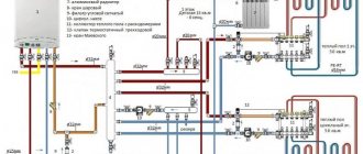
Schemes of pumping and mixing units
Pumping and mixing units are assembled in several ways, the difference lies in the connection of the pump and in the form of a valve.
Node connection diagrams
Pump-mixing unit for heated floors.
With series pump connection
When the pump is turned on, only the coolant is prepared according to a sequential scheme and ensures its movement through the loops. Despite the need for two separate devices for pumping liquid through the primary and secondary circuits, this scheme is more technologically advanced.
It has increased performance than parallel connection. Therefore, professionals often use this option when installing heated floors.
However, for the efficiency of the floor during such an assembly, the correct calculation and settings, as well as the accuracy of the drawn drawing, play an important role.
With parallel
The advantage of a parallel circuit is that only one device is required to pump water through both circuits. This greatly simplifies the assembly process, but a more powerful unit is required.
If the mixing device is planned for a small heating system, then a parallel arrangement is recommended. Since when assembling such a structure with your own hands, fewer problems occur, it is therefore easier to avoid serious errors. But for large areas of heated floors, this scheme is not suitable - low productivity and efficiency.
Other elements
The underfloor heating system contains a huge list of various parts and mechanisms. The need for their use is directly related to specific features. This applies to equipment, connection of pipes, coolant, and required heating.
- Related Posts
- What are the characteristics of Rehau pipes for underfloor heating?
- What should be the height of the heated floor?
- How is the length of a heated floor pipe calculated?
- What is a warm floor National Comfort?
- How much does a heated floor consume?
- How to assemble a Valtec manifold for underfloor heating?
Which mixer is better to choose?
It is necessary to select a thermal mixer taking into account the characteristics of the heating device. When choosing distribution equipment, you need to take into account the method of mixing - central or lateral.
If the area is large, with several separate circuits, then it is necessary to install a mixing unit with a three-way valve. This unit can handle large volumes of liquid perfectly. For a single-circuit floor, a manifold with a two-way mixer is suitable.
You can make a pumping and mixing unit for heated floors with your own hands, but if you buy a ready-made one, we recommend these models:
- VT.COMBI and VT.COMBI.S - for the preparation of low-temperature coolant, a two-way valve is used, it is controlled by a thermal head or servo drive. The temperature sensor is not included in the package - must be purchased separately.
- VT.COMBI - the unit is equipped with a balancing valve, with the help of which the pressure in the system is adjusted.
- VT.COMBI.S - for this NSU model, the collector can be connected both at the input and at the output. Therefore, it is used for two types of heating (radiator and TP).
- VT.DUAL - the mechanism includes two modules (pumping and thermostatic), with a manifold group located between them. Mixing is carried out by a three-way valve with a thermal head.
NSU VT.COMBI.S
These are proven models and it is better to buy them.
Recommendations
When choosing the optimal type of underfloor heating system, you must first take into account the thermal conductivity of the material under which the device will be placed and the branching pipes with other components.
The best option is parquet; in fact, all types of wood are excellent heat conductors. By placing the system under such a floor covering, it will be possible to achieve good heating of the floor surface.
The second important factor is the system itself; it is recommended to choose only products from trusted brands, with the possibility of contacting a repair service during the warranty period.
This will allow you to avoid additional, unexpected expenses if something breaks or malfunctions in the system. The warranty period allows you to fix the problem at the expense of the manufacturer; the work process also includes dismantling and subsequent installation of the floor covering, in fact the entire range of work.
Equipment
The mixing unit is a complex mechanism, responsible for maintaining a stable water temperature and for its continuous circulation. It is included in the collector block and consists of a number of mechanisms.
Pump
The main function of the pump is to create a constant movement of water through the pipeline. It supplies and returns it through the collector and floor branches. Its main indicators are pressure and productivity.
If calculated correctly, the pump will ensure that the hydraulic resistance in the floor line is overcome. It is recommended to use a device with an automatic operating mode switch.
Circulation pump
Flow regulator
Flow meters are:
- Primary circuit balancing valve (float) - it is responsible for the amount of coolant that enters the main line from the primary high-temperature source. The flow is regulated due to its throughput. The adjustment is made by a valve with a head; it is rotated with a key. Adjustment is also carried out by the thermostat valve, which is controlled by a remote sensor.
- Balancing valve of the secondary circuit - it is adjusted depending on the size of the heated area. By opening and closing the control valve, the proportions of the heated and cooled flow change. Closing the balancing valve of the secondary circuit return leads to an increase in the supply of hot coolant from the boiler, and this leads to an increase in thermal conductivity.
The degree of opening is adjusted using a scale printed on the flask. It determines the throughput of the device in m3 per hour.
Balancing valve
Bypass valve
The bypass, together with the bypass valve, helps ensure uninterrupted operation of the pumping equipment when the backpressure mode is in effect - when the circulation of liquid through the floor pipeline is completely or partially stopped. This can happen if the loop valves on the comb are closed manually or using taps.
As a result, the resistance to water flow increases, as well as the load on the mechanism. The pressure level in the system increases and the bypass valve opens.
The coolant flows through the bypass pipes and the pump, thereby closing a small circulation cycle. This leads to the elimination of emergency situations.
Bypass
Auxiliary elements
Auxiliary elements are also responsible for the functions of monitoring and maintaining the efficient operation of the pumping and mixing structure. This:
- thermometer - controls the temperature of the coolant;
- air vent - air is removed from the system through it;
Air vent
- drainage taps, their purpose is to drain water;
- check ball valve - prevents the flow of coolant in the opposite direction.
Collector block
Collector group - heated floor circuits are connected to it, calculated for a certain number of branches. It includes feed and return combs.
Is the VALTEC COMBIMIX pump and mixing unit worth it?
Using the built-in boiler pump
This scheme involves the use of boiler equipment with a built-in pump, the power of which is up to 35 kW. It creates a pressure at the outlet of the tank in the range of 20 - 25 kPa, with a water flow of 1000 - 1500 liters per hour.
The installation process is similar to that of a conventional heating element, but an additional pump for underfloor heating is not required.
To fully utilize the potential of the device and create coolant circulation in the heated floor and radiators, it is necessary to correctly connect the device to the circuits.
This can be achieved in this scheme by ring combination - the boiler with the TP, and with the radiator. These two rings are united by a small common area with low hydraulic resistance, thereby one circuit does not affect the other.
In this scheme, the slant filter acts as a slag catcher, and there are air vents in the boiler, radiator and floor circuit.
The essence of the functioning of the ring circuit is that water flows from the container where it is heated into the pipelines. Pressure surges in the supply and return pipes lead to the movement of liquid through the lines and its return back.
Making a mixing unit with your own hands
When constructing warm water floors, you can choose a ready-made model of a pumping and mixing unit. But if you want to make a budget knot with your own hands, then we will tell you in detail the step-by-step process.
Before you start work, you need to stock up on: a strainer, a three-way thermostatic and check valve, two thermometers, a circulation pump, an air vent, two tees, two drain and ball valves. And also, manifolds - for the supply pipeline with ball valves and for the return pipeline with regulators.
In addition, the number of loops of a warm water floor should be equal to the outlets on the collector.
Step-by-step assembly instructions:
- We mount a mesh filter to the ball supply valve, after which we install a corner.
Screw the filter to the feed
- We screw a three-way thermostatic mixing valve to the corner.
Installing a three-way valve
- We screw a check valve to the mixer, to the side where the return line will be connected - without it, the unit will not work correctly.
Connecting the check valve
- We install thermometers to the return and to the middle outlet of the mixing unit.
We fix the thermometers
- We connect a circulation pump to the thermometer coming from the supply pipe. It is necessary that the straight distance from the thermometer to the pump, and from the pump to the collector, be equal and equal to 10 diameters of the supply pipe.
Installing the pump
- Next, we mount the collectors, which are fixed on a special bracket. We connect the supply manifold with ball valves to the pump, the return manifold will have control valves.
We install the collector group
- We screw tees to the end outlet of the supply and return manifold, to which the air vent is attached.
Connecting the tees
- We install an air vent.
- We install a drain ball valve at the side outlets of both tees. They are necessary to fill or drain the system.
- We connect a piece of polypropylene or metal-plastic pipe to the return manifold. Its size should be equal to the distance from the supply manifold to the thermometer.
We attach a piece of pipe to the return line
- We place a second mesh filter between this section of pipe and the return thermometer.
Installing a second filter
- We screw the ball valve to the check valve.
Connecting the return valve
The result was a simple, cheap model of a homemade pumping and mixing unit for heated floors.
Ready node
Pumping and mixing unit for heated floors: a budget option
Floor standing gas boiler
It is not recommended for initial consideration. The reason for this is the lack of the following mechanisms in the design:
- circulation pump;
- additional cranes providing dry repairs;
- expansion membrane tank;
- separate group of valves at the heater outlet.
Of course, models are now being produced with all of the above. There the tying becomes easier. In any case, initially everything has to be recorded on the plan. And draw up the scheme with experienced craftsmen.
Floor standing gas boiler
After all, you will have to use a closed system with a specific pressure. The value must be redundant to function. Nuances are discussed at the planning stage.
Installation of the mixing unit
Before installing the distribution unit, it is necessary to determine its location. It can be installed in the room where the floor will be installed, or in the boiler room of a private house.
It is possible to mount the unit directly on the wall or in a metal cabinet, which is mounted into a recess made in the wall. It is equipped with adjustable guides and doors. A collector placed in such a cabinet looks aesthetically pleasing, but it is not cheap. It is important that all electrical appliances are grounded. And also access to the device was free.
The mixer should be mounted at the top point of the system, this will simplify the release of air from it.
The pumping and mixing unit is installed in the following sequence:
- A niche is prepared in which the manifold cabinet is placed.
Making a niche for the closet
Installing a cabinet
- The mixing and distribution unit is installed in the cabinet.
We fasten the pumping and mixing unit
- The corresponding pipes from the boiler are connected to the manifold ball valves.
Connect the collector to the supply
- The floor contour pipelines are screwed to the outlets of the comb.
Connecting the floor pipeline
The heated hydraulic floor structure has been installed, you can check its quality for leaks. Only after this, the screed is poured and the finishing material is laid.
When can systems be combined?
It is permissible to install a combined heating system in premises of any purpose. The main thing is to choose the finishing product and the type of heated floor in accordance with the requirements. The combined design is ideal heating for a two-story private house.
When laying a heated water floor on the first floor, warm air masses, rising, will warm up the floors of the second floor, where only radiators can be installed. For the finishing material on the first floor it is better to choose tiles, and for the second floor any material is suitable.
It is not possible to build a combined system in apartment buildings, since it is prohibited to connect hydrofloors to the heat supply source for the entire house. The solution is to install a heat exchanger.
Homemade designs
The collector has a significant drawback - high cost.
Therefore, many “homemade” people assemble various options for collectors with their own hands, depending on their wallet and the availability of components.
There are two options for this path:
The 3-loop collector circuit can be implemented as follows:
First, you should assemble the collector pipes - return and coolant supplying the heating circuits. To do this, use one comb for 3 channels or 3 single-loop units for each collector.
The return manifold is equipped with a flow sensor or flow meter and a counter-mounted connection unit for return supply hoses along each loop.
Single-loop manifolds are connected by threaded elements into a comb. Each coolant loop contains a heat sensor with an actuator and a connection point for the heating circuit power line.
Air vents are connected to one end of the collectors, and on the other, a coolant pump is connected to the collector pipes, and in addition a thermostatic valve or servo drive is connected to this point, which replenishes the mixer with hot water from time to time.
The assembled collector is attached to the wall, tested for functionality and connected to the thermal circuits. After this, final installation and configuration of the entire system is carried out.
Here is the simplest working version of a manifold for heated floors, available to a wide range of DIYers. The capabilities of real collectors are often expanded by connecting more complex control and metering systems.
For example, they connect heat meters, additional temperature meters and much more, no matter what - that’s why homemade inventors exist, to “assemble something yourself.”
If a homemade manifold is soldered from polypropylene pipes, then you need to replenish your arsenal of tools with a special soldering iron for welding parts made of this polymer.
When assembled by welding, the size of each single-loop unit increases due to the seams, and if there are more than 3 thermal circuits, then the entire collector becomes bulky and its installation becomes problematic. Otherwise, the design of the plastic manifold and its settings are no different from those described earlier.
Well, now it's time to finish the article. All the material I wanted to share has been reviewed. I hope it will be useful to you, and you will use it if you need to install a mixer for heated floors with your own hands. Improve your own practical skills and gain new knowledge, as they say: “It’s never too late to learn!” That's all, thank you for your attention, successful and easy repair!
Model overview
In the article, we defined the criteria by which we will compare devices. Now we will compile a list containing information on specific models. Unfortunately, it’s difficult to insert the price and configuration (the cost is constantly changing, and the description of the location of components takes up a lot of space), but we’ll write down some important data. To get acquainted with the remaining characteristics, you can follow the links to product cards.
| Brand : TIM ProFactor Zeissler | Max pass. capable m3/h | Max thermal power kW | Operating principle last / par | Control method r,t,e,p* | Price $** | Comments (***) |
| JH-1032 | 2.1 | 20 | after | t r, p, e* | 75 | Lpump=130 Gpump=25(1½") dl=1″ D-V=272-270 |
| PF MB 840 | 85 | |||||
| JH-1033 | 5 | 20 | after | t r, p, e* | 139 | Lpump = 180 Gpump=25(1½") dpodkl=1″ D-V=219-443 |
| JH-1035 | 2.1 | 20 | after | t p,e,p* | 39 | Lpump=130/180 Gpump=25(1½") dconnection=1″ D-V=197-289/343 |
| JH-1036 PF MB 841 | 4.8 | 12.5 | after | t p,p,e* | 45 | Lpc = 130/180 Gpc = 25 (1½") dconnect = 1″) LxH = 227×365/415 |
| NG-TK-0101 | 9.8 | 24 | village | t r, e, p* | 95 | Lpump=180 Gpump s=25(1½") dconnection-top=1″ dconnection-bottom=1½" L x H=255×364 |
| Brand : TIM ProFactor Zeissler | Max pass. capable m3/h | Max thermal power kW | Operating principle pos/paral | Control method p/t/e/p* | Price $** | Comments (***) |
| JH-1038 | 4.5 | 24 | paral | t r/p/e* | 106 | Lpump s=130 Gpump=20(1″) dpodkl=1″ D-V=316-254 |
| JH-1039 | 2.1 | 20 | paral | t r/e/p* | 72 | Lpump=130 Gpump=25(1½") dconnection l=1″ D-V=267-289 |
| PF 842 | 10 | 45 | village | r e* | 117 | Lus os=130 Gpump=25(1½") dconnection=1″ D - H=250-357 |
| JH-1037 | 4 | 15 | village | t p/e/p* | 124 | Lpump s=130 Pump G=20(1″) dpod to=1″ LxH=316×378 |
| NG-MK-0101 | 9.8 | 24 | village | r e* | 78 | Lus os=180 Gpump=25(1½") dconnection-top=1″ dconnection-bottom=1½" L x H=255×364 |
*
- with an asterisk, those options that can be purchased separately.
The decoding is as follows: p - manual, t - thermomechanical, e - electrothermomechanical, p - electrically driven **
- the cost is approximate, see the exact price on the product card
***
- L Pump = pump connection size, Gpump = pump connection diameter, dconnect = diameter connections to external equipment, D-H = overall dimensions (Length - Height).
When compiling the table, we relied on information from passports and tried to compare numbers with similar inputs, but this was not always possible. For example, somewhere the thermal power is indicated at a drop of tc = 7°C, and somewhere 10°C, and the figures of 20°C were not taken into account at all. In addition, the form factors of different instances are aimed at different conditions. Let's take a case - a center-to-center distance of 125 millimeters at the input of the device fits well with hydraulic arrows, but worse with combs. And, conversely, versions with an output of 210 millimeters are easily connected to collector groups.
RESULTS
We hope that our approach and dry numbers were useful to you. In the end, we would also like to express our subjective opinion, which was formed based on the results of observations during sales and on the basis of feedback from installation specialists who contact us. So, overall, our favorites are the JH-1036 and JH-1033.
TIM JН-1036
Pros:
- The most budget-friendly;
- Allows the use of popular pumps of both 130 and 180 mm;
- It has a modern design and has good capabilities for adjusting the flow;
- The most purchased by visitors.
Minuses:
- Capable of passing a relatively small volume of media through itself;
- Inconvenient connection from below.
Connection via three-way valve
A slightly different assembly and operating principle is the option of connecting a heated floor through a three-way valve, which is shown with an arrow in the diagram below.
This scheme is used in cases where, in addition to a heated floor, the system also contains a main heating circuit. The temperatures of the coolant in them will be different, which is why a mixing valve is needed.
Connection via three-way valve
- This device not only regulates the water supply to the circuit (it is mounted on the supply pipe in front of the circulation pump), but also at the same time, using a built-in thermostat, controls its temperature, mixing cold coolant with hot one. In this case, the pressure in the pipeline corresponds to the pressure set on the pump.
- However, the valve cannot accurately dose the amount of water for mixing, so the temperature in the floor circuit may be either underheated or too hot. The problem is solved by connecting a servo drive to it, since it is this that balances the operation of the system and protects the floors from overheating.
Three-way mixing valve
The circuit with a mixing valve is quite accessible for self-installation, and the equipment for it does not require large expenses.