The uninterrupted operation of any heating device depends on the correct selection of components, and water heated floors are no exception. In this design, an important point is given to maintaining the temperature level and intensity of coolant supply - this function is assigned to shut-off valves: a two-way or three-way valve.
In our article we will tell you what a three-way valve is, the principle of its operation, and what types there are. You will also learn which valve to choose for a heated floor, as well as how to install it yourself.
Application area
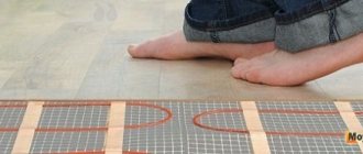
Underfloor heating systems are increasingly popular in residential buildings today, but without a control valve it is impossible to ensure proper heating. A three-way tap is an element designed to adjust the heating level in a water floor that is filled with screed.
The valve is installed both as a complete set with a mixing and distribution unit, and as an independent device. In small rooms (bathtub, toilet, kitchen), there is no point in installing a multifunctional collector - it is expensive and not justified.
A three-way thermomixing valve can control the temperature and regulate the volume of liquid for such rooms.
Main areas of use:
- In a radiator heating system.
- In the DHW system.
- In warm floors.
Expert advice
Before choosing control equipment, you need to decide what area needs to be heated. If you will be heating a bathroom, part of the floor of a bedroom or a children's room, there is no need to purchase fittings with a thermal head - it is easier to use a manually operated three-way valve than to install a full-fledged expensive mixing unit.
The cost of a mixing and distribution unit with shut-off and control valves, a manifold, a pressure gauge, and a Mayevsky tap exceeds the cost of all pipelines (if they are made of polymer and not expensive copper).
If the underfloor heating system includes several rooms, then it is necessary to order a project from a qualified plumbing engineer before installation - it will indicate the characteristics of the valve. If there is a large area of heated floors and a large number of rooms, one or more mixing units will be needed.
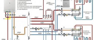
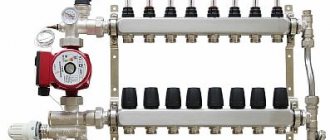
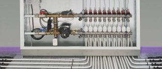
The connection diagram of each unit includes a manifold - a distribution comb, to which heating pipelines are connected. A three-way mixing valve and pump are installed in front of the manifold. The valve can be with a thermal head or with sensors, a controller and an electric drive.
Functions
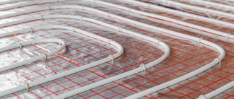
Water heated floors have significant differences from standard radiator heating. The floor pipeline, which lies in a cement screed, requires water at a certain temperature level, much lower than that circulating in the radiators. Therefore, it is necessary to install a three-mix running unit, in which the coolant will be brought to the required degree.
Bringing the liquid to the required degree of heating that meets the standards for underfloor heating (which ranges from +35 to 55 degrees) is the main function of a three-way thermomixing valve.
Other elements
The underfloor heating system contains a huge list of various parts and mechanisms. The need for their use is directly related to specific features. This applies to equipment, connection of pipes, coolant, and required heating.
- Related Posts
- How to install damper tape for heated floors?
- How is the mesh for underfloor heating installed?
- How to lay heated flooring under laminate on a concrete floor?
- What is included in the Valtek heated floor kit?
- How to make a warm floor?
- How to install heated floors under porcelain stoneware?
Design and principle of operation
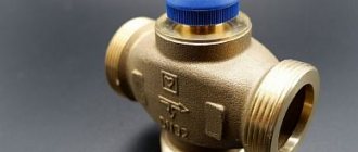
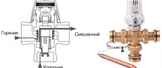
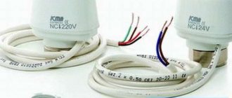
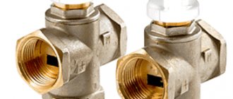
A mixing valve is a device for mixing and regulating water flows; it has three openings: two inlet and one outlet. In the space between the inlet holes there is a heat-sensitive damper; it is responsible for regulating the movement of liquid - cooled and heated. Modern devices are equipped with a thermal head or control valve.
The heating floor valve operates continuously. The step-by-step process is as follows:
- heated water is supplied to the first inlet - its temperature is determined in the valve;
- if the heating degree of the water exceeds that required for heated floors, then the supply of cooled liquid from the return line opens through the second hole;
- inside the valve, heated liquid is mixed with cooled liquid;
- after obtaining the desired temperature, the return flow is closed;
- The coolant is supplied through the outlet to the underfloor heating pipes.
For the thermal valve to work effectively, it is necessary to maintain constant pressure in the line.
When operating an automatic thermo-mixing tap equipped with a servo drive, heating is carried out in 3 minutes ; if there is a thermal head, the liquid is heated in 15 minutes .
The procedure for connecting a wall-mounted boiler
The piping of a boiler that is mounted on the wall is much simpler than the others. As a result of the purchase, the following mechanisms are discovered:
- chimney;
- fan;
- pressure meter;
- closed combustion chamber with burner;
- heat exchanger (DHW);
- hydraulic unit;
- gas valve;
- Control block;
- pump.
This is what a wall-mounted gas heating boiler consists of. Proper functioning begins with following simple rules. Any communications are blocked immediately when necessary. The return circuit before the heat generator has a corresponding filter.
Its task is to exclude sand from within the overall system. The front side of the element faces the floor. Cleaning through the cork takes place in the shortest possible time. It is ideal to install the same protection on the cold water inlet circuit.
The lowest point of the heating system has a special fitting. It is recharged directly from the water supply. Moreover, a shut-off valve or check valve is cut into the main line.
The latter is made according to the spring type principle. Similar step-by-step instructions are available online. Communications are allowed using plastic pipes. Their advantage is the absence of emergency overheating.
Kinds
Esbe three-way for heated floors, why is it needed.
Three-way thermal valves come in separate and mixing types. For underfloor heating, mixing valves are used.
In addition, they have different implementation methods; they can be manual or automatic. They also differ in their design - the location of the holes (inlet and outlet).
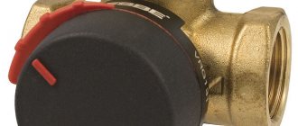
Manual
The price of a manual device is not high, but it is rarely used because it is not convenient. Suitable only for small rooms - bath, kitchen. The temperature level and volume of supplied coolant are adjusted manually using a handle.
Automatic
Automatic valves have a thermal head or an electric drive, which can be controlled by a sensor.
Types of mixing units:
- Simple - if the temperature rises, the liquid expands, the damper opens, cold and hot water mix.
- Three-way valves with a thermal head with a remote thermostat for heated floors are more advanced models. They are widely used because they are accurate and do not require electricity to operate. Average price from 500 rubles to 2500 rubles.
- Three-way valves for heating with a thermostat - they regulate the flow of heated and cooled water, and also control the temperature with a built-in thermostat. The expansion and contraction of the holes occurs automatically, depending on the temperature of the liquid.
- With an electric drive (drive with a magnet or servo drive) - the damper in the valve is activated under the influence of an electric motor, it is controlled by a controller, and a signal is received from a temperature sensor. They are easy to connect, so they are widely used. But unreliability is their main drawback, since they depend on electricity. Their cost is higher than with a thermal head, approximately 4 - 5 thousand rubles.
- With pneumatic or hydraulic drive - used more often in production, for devices with high pressure. They have a high cost, but their service life is longer.
- Electronic - adjustment is carried out by a built-in electric motor or a control element with a thermometer.
Do you need a hydraulic gun?
A hydraulic separator (hydraulic arrow) is a device that is usually placed between the boiler and the collector; it provides zero resistance in this area. Visually, the element is a hollow pipe with 4 pipes: on one side, two are intended for the boiler, on the other, for the collector. The question of installing a hydraulic separator arises when there is a need to install more than 4 pumps and more than 1 boiler.
The hydraulic arrow can be fixed vertically or horizontally, it does not matter. The first option is often chosen, as it simplifies the installation of the air vent in the upper part. A tap can be attached to the bottom to remove sludge.
Often in articles this device is attributed properties that it does not possess. We list the tasks for which you should not buy a hydraulic gun.
- Does not increase boiler efficiency
- Does not reduce fuel costs
- Does not protect against heat stroke
- You still need to select pumps for each circuit separately.
- Not intended for air bleeding or sludge protection.
The hydraulic arrow can worsen the operation of the system if the pumps are incorrectly selected. For example, a boiler unit is much inferior to the total power of devices on other circuits. As a result, the coolant reaches the comb already cold due to mixing with the reverse flow.
Are a manifold and mixing unit required?
In a small house, a heated floor may not take up so much, in which case the costs of a collector and mixer will not be worth it. The simplest solution would be to install a heated floor with one or two circuits, controlled by a TSG thermal head or an RTL tap. Regulation in this circuit occurs by limiting the temperature on the return flow.
The RTL valve is not intended for installation on a manifold; it has high hydraulic resistance. Due to the large size of the head, it is inconvenient to screw the element onto a distribution unit with a large number of adjacent circuits. This also makes it impossible to use built-in plumbing cabinets. It is not recommended to install RTL cranes on a circuit longer than 70 meters. The thermal head is usually placed in a plastic box that is hung on the wall.
The TSG head also limits the return flow, but has a Eurocone, so it can be installed on the return of the manifold. The actuator acts on the stem, and not on the valve itself. In this case, the head is occupied by the working valve of the manifold, because of this, installation of the servo drive becomes impossible. The absence of resistance makes it possible to install a longer circuit.
Manufacturing materials
Three-way thermomixing valves are made from the following materials:
- Brass is a copper alloy with zinc additives. The product is not subject to corrosive destruction, it is strong and durable. Sometimes these thermomixers have a chrome or nickel coating, which protects against darkening. This option is most often used in residential areas.
- Bronze is a copper alloy with tin additives. It is rare, although the quality is no worse than brass.
- Stainless steel is an excellent metal for making control products. It is characterized by durability, strength, and corrosion resistance. But the cost of appliances made from it is high, so they are not suitable for a private home.
There are titanium and carbon steel regulators, but they are recommended for industrial use. Valves are produced from silumin (an alloy of aluminum and silicon), their disadvantage is low strength.
Advantages and disadvantages
Three-way thermostatic mixing valves are simple in design, yet reliable and durable. Their use allows for high-quality and precise control of the floor heating level.
Thermostatic valve for heated floors: types and their design, how to choose, installation diagrams and alternative connection methods
The devices are sealed and compact. Plus - they do not allow the pipes and screed to overheat, which extends the life of the system.
The benefits of control valves are irrefutable, but they have a number of disadvantages:
- They increase hydraulic resistance - this negatively affects the functioning of a unit that has more than one collector.
- There is a risk of a large volume of hot coolant entering the floor pipes. And this can lead to leakage and airing of the system. Such problems most often occur when the device is starting up.
Disadvantages of mixing units
Despite the obvious benefits, three-way valves are not without some disadvantages:
- Increasing the hydraulic resistance of the system. This can be especially noticeable in complex networks that have multiple collectors, pumps and mixing units.
- The likelihood of a sudden surge of large volumes of hot water into the heating circuits. This risks airing the system and can even lead to leaks. This problem most often manifests itself at the stage of system startup, so this stage of work should be treated very responsibly.
Manufacturers
Preference should be given to mixing valves from manufacturers that have proven themselves well in the market. Such companies include:
- Esbe (Sweden) - occupies a leading position in the quality of products of this type. The valves are reliable, with a warranty period of more than 5 years.
- Valtec is a Russian-Italian company; its mixing taps have good characteristics at an affordable price. Warranty - 7 years.
- Honeywell (America) - the priority of mixers from this company is considered to be convenient and uncomplicated installation. They are reliable, but expensive.
However, it should be remembered that even high-quality products if installed incorrectly will not ensure correct operation of the system.
How to choose?
It is recommended to select a three-way valve in specialized stores. When choosing a model, you need to take into account its characteristics. When purchasing a device you need:
- study all documentation - warranty, manufacturer’s certificate, installation and operating instructions;
- give preference to bronze or brass devices - they will not expand when heated;
- based on the valve capacity - this parameter must correspond to the boiler performance;
- select a valve with a cross-section that exactly matches the size of the floor pipes; if there is a mismatch, you will have to buy adapters.
An important point is that even the apparent coincidence of the diameters of the valve inlet and outlet does not indicate the throughput level. This is affected by the size of the internal cross-section of the holes. This parameter is specified in the accompanying documents.
You need to choose a device based on the size of the heated room - for large areas an automatic device is recommended; it is able to maintain heating at the proper level. For small rooms, a simple one with a thermal head will do the job, so there is no point in overpaying for a more complex model.
When purchasing, you must visually inspect the device for chips and cracks. If the device is brass, then the inside should be golden.
Purchasing automatic devices will facilitate the adjustment process. And the presence of software will allow you to adjust the temperature taking into account the time and day of the week.
Mixer assembly on the pump
This becomes an important element of the entire system. After all, it regulates the throughput and controls the water temperature. Shut-off valves are immediately replaced with thermostatic valves.
We recommend: How to install heated flooring under laminate on a concrete floor?
Installation on the general circuit is carried out anywhere. The main thing is that it is located between the inlet and the supply manifold. The third outlet of the water flow carries it further. The return manifold sets its temperature, and cold water dilutes it.
Heated floor diagram with a three-way valve
A three-way valve can be installed together with a mixing and distribution unit, or as a separate device.
Three-way valve. We install it correctly.
Scheme with separately installed valve
If the valve is mounted separately, it takes over all the functions of the manifold. This scheme is intended for small rooms, no more than 25 m2. The temperature level is adjusted using a special device and a thermostat, they are located in the valve.
The disadvantage of using a valve according to this scheme is that there is no way to dose the flows.
The system looks like this:
- a three-way valve is installed on the hot coolant supply pipe;
- a temperature sensor is attached behind it;
- Next, a circulation pump is installed; it will deliver water with the required heating degree to the sex pipeline.
Scheme without mixing unit
Valve with mixing unit
If the area is large, then it is necessary to use a scheme where the valve is part of the distribution unit.
It will ensure uninterrupted operation of the floor heating device, and the water entering the floor line will be at the required temperature and volume.
The connection diagram is as follows:
- a pump is installed on the supply pipe; it will pump the heated coolant from the source;
- then a temperature sensor is installed, it will control the degree of heating;
- at the next stage, a three-way valve is attached - it mixes the coolant to a given degree;
- a tap is placed on the return circuit through which cooled water will flow into the three-way device.
Scheme with a mixing unit
That is, coolant heated to the required temperature will be supplied to the underfloor heating pipes.
Connection diagrams depending on design
In addition, the connection diagrams differ in the design and direction of the coolant in the device, there are:
- L-shaped - the product is equipped with two holes on the side and one round hole on the bottom of the body. The heated liquid is supplied to the side inlet, and the cooled liquid is supplied to the bottom. After mixing, the water moves into the floor branches through another side hole.
- T-shaped - both flows, cold and hot, enter the mixer through the side inlets. The mixed coolant is sent to the floor through the central lower outlet.
When deciding on a diagram for installing a three-position valve, you should consider how it will fit into the pipeline piping.
Making a mixing unit with your own hands
When constructing warm water floors, you can choose a ready-made model of a pumping and mixing unit. But if you want to make a budget knot with your own hands, then we will tell you in detail the step-by-step process.
Before you start work, you need to stock up on: a strainer, a three-way thermostatic and check valve, two thermometers, a circulation pump, an air vent, two tees, two drain and ball valves. And also, manifolds - for the supply pipeline with ball valves and for the return pipeline with regulators.
In addition, the number of loops of a warm water floor should be equal to the outlets on the collector.
Step-by-step assembly instructions:
- We mount a mesh filter to the ball supply valve, after which we install a corner.
Screw the filter to the feed
- We screw a three-way thermostatic mixing valve to the corner.
Installing a three-way valve
- We screw a check valve to the mixer, to the side where the return line will be connected - without it, the unit will not work correctly.
Connecting the check valve
- We install thermometers to the return and to the middle outlet of the mixing unit.
We fix the thermometers
- We connect a circulation pump to the thermometer coming from the supply pipe. It is necessary that the straight distance from the thermometer to the pump, and from the pump to the collector, be equal and equal to 10 diameters of the supply pipe.
Installing the pump
- Next, we mount the collectors, which are fixed on a special bracket. We connect the supply manifold with ball valves to the pump, the return manifold will have control valves.
We install the collector group
- We screw tees to the end outlet of the supply and return manifold, to which the air vent is attached.
Connecting the tees
- We install an air vent.
- We install a drain ball valve at the side outlets of both tees. They are necessary to fill or drain the system.
- We connect a piece of polypropylene or metal-plastic pipe to the return manifold. Its size should be equal to the distance from the supply manifold to the thermometer.
We attach a piece of pipe to the return line
- We place a second mesh filter between this section of pipe and the return thermometer.
Installing a second filter
- We screw the ball valve to the check valve.
Connecting the return valve
The result was a simple, cheap model of a homemade pumping and mixing unit for heated floors.
Ready node
Pumping and mixing unit for heated floors: a budget option
Installation and connection of a three-way valve to a warm floor
Connecting a three-way valve to a warm floor is not difficult; you can do it yourself. The main thing is to follow the steps according to the attached instructions.
All inputs and outputs are indicated by letters:
- A - input for heated coolant;
- C - inlet for chilled water;
- AB is the outlet.
Before connecting the device, it should be taken into account that it may need to be dismantled, so it is necessary to have an unobstructed approach to the unit.
Materials and tools
Before installing the valve, you need to stock up on the necessary tools. You will need wrenches (2 pcs), pliers, American nuts with union-type gaskets, FUM tape.
Work progress
Connecting a heated floor to the heating system. Three-way mixing valve.
First of all, the three-way valve must be checked for functionality.
To do this, the minimum value is set on the regulator, then hot water is released through the valve. If the device is functioning correctly, the damper should close immediately.
Installation of the tap must be done together with the installation of the manifold group and before pouring the screed.
When using any scheme, the valve is installed using American union nuts.
The work looks like this:
- The fittings located at the ends of the pipes are cleaned of dirt and burrs.
- The same procedure is done with the valve pipes.
- The nut is checked for gaskets.
- Then screw the nuts onto the pipes and tighten them - but not too much. This procedure involves two wrenches - one for tightening the nut, the second for holding the valve.
- A mechanical filter is installed in front of the valve.
It is necessary to monitor the correct connection of the valve outputs: to A - hot water, to B the bypass coming from the return line, to AB the manifold with floor outlets.
To ensure the tightness of the joints, it is recommended to screw plumber's tape or FUM tape.
System check
In addition to the correct installation of the mixing tap, its operation must be checked. System testing is carried out with the coolant heated to 25 degrees. The time for crimping is 24 hours.
After checking, you can proceed to pouring the screed.
Features of installing a water floor in a high-rise building
It is believed that the construction of a water floor system in high-rise buildings is impossible, but this is not entirely true. In practice, such a project can be implemented, but requires agreement with the central heating service provider. They can be installed exclusively on the first floors of buildings.
How to make a water floor in a multi-story building?
Two options are used here: completely replacing the radiator system with a water floor or installing an additional heating system along with the operation of radiators.
The optimal location for connecting a water heated floor system in an apartment building is the place where the return of the common riser is connected to the main line that discharges the coolant to the boiler room
In the first case, it is necessary to carefully calculate the coolant flow in the new system, since it must correspond to the previous volumes. It is not necessary to reconstruct all the heating in the apartment; you can limit yourself to just one room.
If the water floor plays the role of auxiliary heating, heat meters will be needed. In addition, it is necessary to clarify whether a centralized heating system can cover the increased power and coolant consumption.
If a high-rise building has a radiator system with overhead wiring, then it is best to connect the water floor at the junction of the return of the common riser with the main line leading to the boiler room. Filters must be installed in front of the water floor.
This is necessary, given the low quality of the coolant in domestic centralized systems, otherwise the heated floor circuit will very soon become clogged.
Filters should be cleaned regularly. They are more than relevant when directly connected to a central heating system, but the use of a heat exchanger helps make the problem of blockages less acute and the operation of the water floor more stable.
But you will need to install an expansion tank, a heat exchanger, a safety group and a filter.
Subtleties of collector installation
When installing a water floor collector, the supply part of the device must be placed higher than the return. You can do the opposite, but such a rearrangement does not make much sense.
The collector will work, just with the upper return part of the heat from the supply part will be transferred to the reverse flow, i.e. thermal energy is simply lost.
When assembling and installing a water floor collector assembly, it is extremely important to connect all the elements of this device in the correct order, for example, using this diagram
An important point is the installation of flow meters. They should be installed specifically on the supply part; on the “return” side these elements are useless.
In addition to collectors, flow meters and servos with temperature sensors, for installation you will need a drain valve, as well as a Mayevsky valve with an adapter, connecting elements for water floor pipes, a shut-off valve, etc.
Unlike heating collectors, when installing a water heated floor, flow meters are always installed on the supply side, and servo drives with thermostats are installed on the return line
A manifold cabinet is designed to install all these devices. This is a metal box with doors, inside there are adjustable guides. This device greatly facilitates installation, but is not cheap.
Therefore, if there is a niche of suitable size in the area of the installation site, you can use it.
If the collector is mounted without a special cabinet, it must be suspended on brackets. As for the installation location of the collector, the rule applies in this regard: the higher, the better, i.e. It is best to install the collector at the highest point of the system.
The manifold cabinet is a very convenient device that facilitates the installation of a water heated floor system. But if you want to save money, it can be replaced with a niche in the wall
This is due to the need to remove trapped air from the system, for which a Mayevsky valve is installed at the top point of the collector. In addition, it is best to install the collector at an equal distance from all rooms, i.e. closer to the center of the system so that the lengths of individual circuits vary minimally.
Typically, only nine separate underfloor heating rings can be connected to one manifold. If the heating system is too complex and more than nine circuits need to be installed, two or more collectors will be needed.
In a multi-story building, it is not always possible to install a collector at the top. Then you can place it lower, even in the basement. But the problem of removing excess air from the system will have to be solved differently.
The Mayevsky tap on the collector itself will be useless. An air vent device together with a shut-off valve installed in front of it will have to be installed on the return line of each circuit.
Installation is carried out in the area between the pipe and the collector; free access should be provided to the Mayevsky tap.
Thus, if the collector is installed too low, instead of one Mayevsky tap, as many air vents will be needed as the number of circuits will be laid. Plus the same number of shut-off valves.
The collector is installed according to the following scheme:
- Installing a collector cabinet or preparing a special niche.
- Assembling the manifold, installing additional modules: servos, flow meters, etc.
- Connection of the manifold supply to the pipe leading from the boiler.
- Installation of a shut-off valve on the collector return.
- Installation of the collector in a cabinet/niche.
- Connecting pipes to the supply and return parts.
- Installation of the mixing unit.
- Checking the quality of installation, eliminating deficiencies.
Typically, the installation of the collector begins even before laying the pipes and pouring the screed, so you need to take into account that upon completion of the work the floor level will rise noticeably. The manifold cabinet already takes this point into account.
But when installation is carried out using brackets, the device should be placed approximately one meter from the subfloor.
Do not install the water heated floor collector too low; lack of space can create problems when connecting pipes to the connectors
Do not hang the collector too low; this position may complicate the process of connecting pipes. The connection to the polypropylene pipes leading from the boiler is made using a connector on which there is a nut for the manifold thread and a coupling for polypropylene pipes.
The air vent must be installed at the top of the manifold, and its head will be directed upward. But the heads of elements such as flow meters and servos will point down when installed correctly.
Typically the thread on the manifold is three-quarters of an inch, but Mayevsky valves have a half-inch thread, so you need to use an adapter. The adapter material must match the manifold material.
There are two threads on the return pipe of the manifold, one of them is needed for connection to the heating boiler, and the second is for installing a shut-off valve.
All threaded connections require sealing, which can be achieved using an O-ring or, if such a ring is missing, by winding tow, linen thread, FUM tape, etc.
When assembling a mixing unit for a water heated floor, all threaded connections should be carefully sealed using FUM tape or other materials
When connecting a metal-plastic pipe to the manifold connector, the edge of the pipe must be flared and cleaned. This measure will protect the seals from accidental damage.
After this, put a union nut on the pipe, then a crimp washer, carefully attach the pipe to the connector, tighten the nut by hand, and then carefully tighten it with an adjustable wrench.
A mixing unit should be installed before or after the collector. If the installation of this unit is not intended for some reason, a bypass with a shut-off valve is installed instead.
The mixing unit is usually secured using union nuts. Such elements require the mandatory use of rubber gaskets.
Common installation mistakes
The most common mistake when installing a three-way valve is that the supply and return floor circuits are incorrectly connected. For example, when floor contour pipes are connected to the inlet.
Therefore, care is required; for this, there are letter designations at the mixer outputs. If you mix up the holes, the device will not function.
In addition, it is necessary to strictly follow the manufacturer's instructions regarding the distance between straight sections before and after the screw. If this rule is violated, the functioning of the regulator will be disrupted.
Features of operation
When operating a heated floor mixing valve, there are special points. The main one is the mandatory installation of a filter. In addition, it is not recommended to place a mixer with a thermal head in a manifold group that serves more than one room or is located in an adjacent room. A device with a remote temperature sensor placed in a heated room is suitable.
The mixing valve is the main element in the water heated floor system. The quality of room heating depends on how correctly it works. Therefore, its selection and installation must be approached responsibly. If you are not confident in your abilities, then it is better to invite a professional.
Purpose of using the collector
A collector is a device with which the coolant flow is distributed over individual circuits of the water floor and then returned back for heating. The collector unit looks like two pipes with holes to which the system circuits are connected.
The presence of a distribution manifold in the heated floor arrangement makes it possible to control the volume of coolant flow. One of the collector pipes is the supply pipe; hot water flows to it and the inputs of the water floor circuits are connected to it.
The return circuits are connected to the return pipe of the collector. The openings to which this connection is made are usually equipped with threaded, fitting or other connections.
The collector consists of a number of elements such as the collector itself (1 and 2), an adapter for the Mayevsky tap (3); drain valve (4); air vent (5); valve (6); bracket (7); Eurocone (8)
Various devices are also installed here with which you can regulate the coolant flow rates. The simplest version of an industrial manifold is a pipe with a connector called a Eurocone. This is a completely convenient and reliable unit, but it does not allow you to control the flow of water.
To effectively use such a device, you will have to additionally purchase and install a number of elements.
The manifold made in the DPRK is a little more complicated. In addition to the connections at the outlets, valves are installed here; no automatic means of regulating the flow are provided. This is an excellent and inexpensive option for a water floor in a small area with two or three contours of the same length.
Such a system does not require complex management. But on large areas, this type of collector will have to be supplemented with automation.
In addition, the center-to-center distance between the feed and return sections of Chinese devices does not meet the standards adopted in Europe, which can cause problems when connecting it to European-made devices.
Ball valves in such devices are sensitive to low-quality water, and over time they begin to leak. To fix the problem, it is enough to replace the O-rings, but you must take into account the fact that the need for such repairs will arise periodically.
If the operation of the water floor system is intended to be automated, it makes sense to purchase at least a manifold with control valves.
Servo drives can be installed on such valves, connected to thermostats in the rooms. This will ensure automatic control of the coolant flow in accordance with data on the air temperature in a particular room.
To automate the operation of a water heated floor system, flow meters are installed on the collector supply (indicated by a frame), and connectors for servo drives are installed on the return (blue caps at the bottom)
It is most difficult to control a water floor system in which the individual circuits vary markedly in length, but in complex systems this is usually the case. In such a situation, the optimal choice would be a manifold with flow meters installed on the supply side, and sockets intended for mounting servos on the return side.
Using flow meters, it will be possible to adjust the intensity of the coolant flow, and servo drives in conjunction with thermostats allow you to set the appropriate temperature on each circuit.
If there is no need for automatic control, you can purchase a supply manifold with flow meters, and a return manifold with conventional valve taps.
It happens that it is not possible to choose a collector with the number of connection sockets that corresponds to the project. Then you can take the device “with a reserve”. And the extra holes are simply closed with plugs.
This solution may be useful if you later need to add a couple more loops to the water floor system.