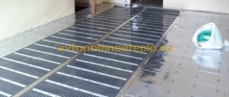
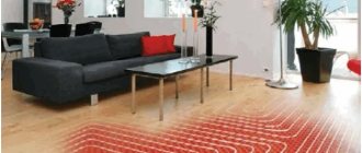
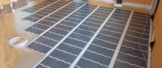
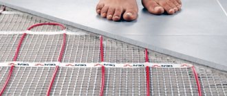
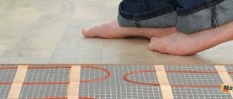
The “warm floor” system has taken root well for heating in private homes. Some heat individual rooms with water, and some even equip such a system for the entire house. Also, conventional heating radiators are often combined with such heating, which require hotter water for normal operation.
To do this, they make a unit for mixing the heated floor, which we will tell you about in this article.
Operation of the water mixing system
Why do you need a mixing unit?
It is worth immediately noting that the mixing unit for heated floors is used only in conjunction with a water heating system .
Typically the heating system is organized in this way:
- One heating boiler;
- Heating fluid;
- High temperature circuit for radiators;
- One or more circuits for heated floors.
The boiler heats the water to 75-95 degrees, and according to sanitary standards, the maximum surface temperature should not exceed 31 degrees. This is primarily due to the comfort of being barefoot, as well as the peculiarities of using many floor coverings for an apartment or house.
Advice! If we take into account the thickness of the screed and floor covering, then the temperature in the pipes should be 35-55 degrees. It is for this purpose that the underfloor heating circuits are connected not directly, but through a mixing unit. Their use is not necessary if the heat source does not heat the water too hot and the house no longer uses high-temperature circuits.
Features of laying heated floors with a snail
If underfloor heating is the only heating option, then the room is conventionally divided into 2 zones: edge and main.
The edge zone is located along street walls and window openings, where the overall heat loss is greater. If there is one cold wall, the edge zone has a rectangular shape with a side deep into the room - 1 m. In the corner room, where two street walls meet, the edge zone is made L-shaped.
In the edge zone, pipes are laid in smaller increments, approximately 10 cm.
Whereas in the main zone the laying step is usually 20 cm. In a large room, the edge and main zones are formed with two loops of pipes. For a small area, make do with one loop.
It is laid differently in different areas. It requires a certain skill and experience to masterfully lay out one loop in two different zones. Moreover, the main principle must be observed: the smaller the laying step, the greater the heat flow.
How does the water mixing system work?
Mixing system for several rooms
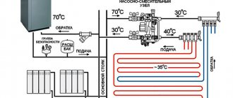
Relatively speaking, the mixing unit for a heated floor works like this:
The hot liquid reaches the underfloor heating manifold and is stopped using a safety valve if its temperature is too high. The pressure triggers the damper and begins to supply cooled liquid from the return (which has already passed through the circuit and cooled down). As soon as the temperature becomes optimal, the valve closes back. There are several ways to organize water mixing, which we will discuss below.
Also, often the collector unit not only maintains the optimal temperature level, but also increases the pressure in the circuit to improve circulation.
It usually consists of the following elements:
- The safety valve we described above. It turns on mixing if the temperature gets too hot.
- A circulation pump that increases water pressure and makes heating even.
In addition, the unit may also include a bypass - to protect against overloads, valves for draining water and air vents. Depending on your requirements, its assembly can be done in several ways.
The mixing unit is always installed before the heated floor contour, but the location of its attachment can be different: directly in the room, in the boiler room or another room in the manifold cabinet.
The main difference between mixing units and each other is the valves used in them. The most popular are two- and three-way valves.
Two way valve
Two way supply valve
Also, such a valve is often called a supply valve. It has a thermal head with a liquid sensor that constantly checks the supplied water. If necessary, it cuts off the supply of hot liquid from the boiler.
As a result, water from the return line is constantly supplied for mixing, and when it cools down, a hot portion is added by a valve. Thus, the warm floor of an apartment or house does not overheat and its service life increases. This option has a small throughput, so the adjustment occurs smoothly, without sudden jumps.
Most craftsmen prefer to install this type of mixing, but to use it, the heating area should not exceed 200 square meters.
Three-way valve
This type combines the functions of a bypass valve and a bypass balancing valve. Its main difference is the mixing of hot coolant inside it with cooled return fluid. They are often equipped with servos that control thermostatic devices and weather controllers.
Inside this valve there is a damper, which is installed in the area between the supply and return pipes. By adjusting the position of the damper, the ratio of the supplied water changes.
Three way mixing valve
This type of connection is considered more universal and is well suited for large systems with a large number of circuits and the use of weather controllers.
It is also worth talking about the disadvantages of this connection scheme. It is possible that, following a signal from the thermostat, the valve will fully open and allow 95 degree water into the circuit. In a heated floor system, sudden changes in temperature and pressure are unacceptable; heated floor pipes can simply burst.
The second disadvantage is the large capacity of the three-way valve. That is, even a slight shift in temperature can change dramatically.
Outdoor temperature sensors
Connection together with an outdoor temperature sensor
Weather-dependent sensors automatically adjust the temperature to suit weather conditions. For example, during a sudden cold snap, they give a command to increase the floor temperature.
The valve rotates a maximum of 90 degrees. The controller divides them into 20 segments of 4.5 degrees each and checks the supplied temperature every 20 seconds. If the actual temperature does not correspond to the optimal temperature, the valve is turned 1 notch. In addition, some species may reduce water supply when no one is home.
Of course, this can be done manually, and tighten the valve each time, but it will be difficult to set the optimal heating mode each time.
Design and purpose of a temperature sensor
So, the temperature sensor for a heated floor system is a thermistor protected by a glass bulb, and also has a copper conductor about 3 meters long for connection to the thermostat.
In addition to the glass bulb for tile floors, the temperature sensor itself is also protected by a gel shell. The conductor is insulated with high-quality PVC (polyvinyl chloride) to protect it from external influences and damage. The length of the conductor can be increased, and naturally, reduced, up to 50 meters, the main thing is that there is an undamaged sensor at the end of the conductor.
To easily replace it in the future, it is recommended to place this structure in a metal-plastic tube, even if the manufacturer included a plastic corrugation with a diameter of 16 mm.
The metal-plastic pipe has a smoother inner surface, so it is much easier to remove and install, as well as connect a new temperature sensor in case of failure. These types of temperature sensors are installed in hard floor coverings (under tiles or porcelain stoneware).
Another type of sensors recommended for laminate, carpet, that is, soft types of flooring material, are special plastic cylinders that are connected to the end of the electrical cable.
The principle of operation of the temperature sensor is very simple; when the temperature changes, its resistance changes, thereby giving a signal to the thermostat to turn on or off the heated floor system from 220 V, the most common network in everyday life.
Mixing unit diagram
The most popular diagrams of assembled mixing units are presented below. Each group of collectors will need to install its own thermostats, flow meters and valves. Mixing can occur both before the collectors and at each branch of the collector group.
Mixing unit for Valtek underfloor heating for one circuit up to 20 sq. m.
The photo shows a connection diagram for one heated floor circuit
Valtek single-circuit mixing unit with automatic adjustment
Connection diagram with auto-adjustment
Valtek unit with automatic adjustment for connecting 2-4 underfloor heating circuits for 20-60 square meters.
Connection diagram for multiple circuits
Manifold cabinet for connecting 3-12 heated floor circuits (for 30-150 square meters).
Manifold cabinet
The diagram can also be supplemented with additional elements:
- The balancing valve for the secondary circuit allows you to adjust the ratio of hot and cold coolant from the return flow. The valve is turned using a hexagon. To avoid accidentally shifting its position, it is secured with a clamping screw. It also has a throughput consumption scale (0-5 cubic meters per hour).
- A balancing shut-off valve for the radiator circuit is needed to connect the mixing unit with other elements of the system. It also turns with a hexagon.
- The bypass valve is a fuse that protects the pump from a mode in which the flow of liquid through it stops. It is triggered when the pressure in the system drops to a predetermined level.
Connection diagrams for mixing units are shown in the photo:
Connection diagram for a heated floor to a boiler
It is worth considering that the diagrams may differ depending on the type of heating system: one- or two-pipe. For example, if you have a single pipe system, then the bypass should always be open so that some of the hot water can always pass further to the radiators. In a two-pipe system, the bypass will be closed as it is not necessary.
Note! The collector group does not have to be placed before the circuit with radiators. If you have a small house and the temperature does not have time to cool down much as you move, then the collector can be mounted on the return line to the radiator circuit.
Calculation of a heated floor pipe
You can calculate the pipe consumption per square meter of warm water based on the installation pitch and the area of the room. The results are found using a special formula; they can be grouped into a table and used in the future.
To the calculation results, it is also necessary to add the lengths of the supply sections from the heated room to the manifold cabinet. On average, this is from 3 to 10 additional meters of pipe.
How much does a finished unit cost?
Of course, you don’t have to worry about studying the operating diagrams of different types of connections, but buy an already assembled version of the system. You can find such options in construction stores, but their prices are high. But this will save you from errors during assembly and calculations, because you need to know well the purpose of each part.
Example of incorrect connection
For example, the most popular Italian mixing unit for heated floors, Valtec, with a pump in Russia, will cost you about 15 thousand rubles. An equally popular American mixing unit for heated floors, Watts Isotherm, also costs between 15-16 thousand. If you want to save money, you can assemble such a unit with your own hands from individual parts.
Making a homemade collector
To make a manifold from polypropylene pipes, it is recommended to use structures with a diameter of 32 mm or 25 mm, corresponding tees and shut-off valves.
How many underfloor heating loops will be connected, how many tees and valves will be needed for the manifold. You will also need to purchase a circulation pump and valve for the mixing unit.
If the water heated floor system does not need serious automatic regulation, you can make the collector yourself or purchase a simple model with conventional shut-off valves
To solder pipes, you need a special soldering iron, as well as at least minimal experience in using such equipment. The supply and discharge sections of the collector are formed from tees and pipes. The pipe sections must be very short so that the tees are separated by very little space.
After this, stop valves are soldered, as well as fittings for connecting to the pump, etc. Such a simple device will not be expensive if you do not install flow meters and other control elements.
But a more advanced plastic collector is easier to buy than to make; the cost of such a device is low.
What does a single lever kitchen faucet consist of?
Single-lever models are more stylish, modern and easy to use.
The advantages of such models are:
- Easy to use. You can adjust the temperature and water pressure with one hand.
- Economical. The design of the device allows you to quickly adjust the temperature and intensity of the jet. This allows you to significantly reduce water consumption.
Single lever models consist of elements:
- aerator;
- housings;
- a switch made in the form of a lever;
- "spout";
- cartridge.
To adjust the water temperature, the lever is rotated horizontally. The intensity of the pressure is adjusted by moving the lever in the vertical plane.
The aerator, which is installed on most models, makes use more convenient - the device prevents splashing and reduces noise levels. In addition, the device helps reduce water consumption.
The main element of the single-lever version is the cartridge. It can be of two types:
- Ball. It is based on a hollow sphere in which three small holes are located. Cold and hot water flows through two of them. Third - to output water at the required temperature. The structure is connected directly to the handle, which changes the position of the sphere.
- Disk. Its principle is similar to the operation of a crane axle box. The device consists of two disks made of metal ceramics. One of the planes is movable and moves together with a lever. Each disk has a hole. When they coincide, water enters the system. If not, the flow is blocked.
Models with ceramic cartridges are the most common.
