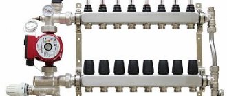
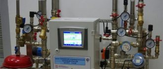
The pump and mixing unit for underfloor heating Valtec Combimix is equipment that ensures a stable water temperature in the secondary circuit (SC). The presence of such a design guarantees the balanced operation of all devices used in the system. In this article we will talk about the features of connecting and configuring such a node.
Device
Several branches can be connected to this model at once, provided that they have a total power of up to 20 kW. The Valtek mixing unit for heated floors is controlled by valves:
- balancing and shut-off (BZ) for the primary circuit (PC);
- balancing for VC;
- bypass;
- drain.
There is also an air vent, thermometers and other auxiliary elements. The BZ valve for PC is used to adjust the volume of coolant. In addition, it is capable of completely blocking the water flow moving into the mixing unit for Valtec heated floors. Control is carried out by unscrewing/tightening the screw. The balancing valve for the VK is responsible for mixing the liquids coming from the manifold and pipeline. It ensures the desired outlet temperature of the mixture.
The Valtec Combimix bypass valve is a safety mechanism in case all other valves suddenly close. In such a situation, it opens a backup path, giving the pump the opportunity to move water idle along a small circuit, thereby protecting the system from an accident. The valve can respond to differences in the range of 0.2-0.6 bar. The critical value is set by turning the knob. According to the instructions for the mixing unit for Valtec heated floors, the task of all other elements is to simplify the operation and maintenance of the system.
Advantages
The pumping and mixing unit for heated floors has a number of advantages in itself and is a practically useful addition to the heating system, improving the following qualities:
- Safety . A system that combines a cold and hot circuit becomes much safer with a mixer. This is due to a decrease in the likelihood of overheating of the heating elements, which means the risk of accidental contact with the hot surface of heating devices or heating system elements is also reduced.
- Economical . The control unit for underfloor heating, which regulates the temperature of heating circuits, allows you to save up to 25-30% on energy resources.
- Hygiene . Since the system constantly operates in the specified mode, there are no problems with its maintenance. It will be possible to carry out wet cleaning in the house without any problems, and all the moisture will dry out very quickly, without having time to cause the appearance of mold and mildew.
- Durability . Each structural element is made of durable materials that can last for several decades without problems.
By connecting the control elements, it will be possible to make the setting of the heating floor mixing unit automatic, i.e. when the temperature changes, the mixer for a heated floor will independently increase or decrease the intensity of the coolant supply, thereby changing the heat transfer of the heating depending on external factors.
Connection
The connection process can be divided into several stages:
- Adjusting the VK balancing valve.
- Setting the pump speed.
- Balancing branches.
- Linking compatibility with other elements that make up the system.
- Adjusting the bypass valve.
- Checking the correct operation of the equipment.
Setting up a Valtec underfloor heating manifold begins with assembly. The pipes are connected using the G1 threaded connection. To connect the secondary circuit collectors, special connectors are used. The circulation pump is installed with the ball valves closed. They must be opened before turning on the device. Before starting testing, make sure that all elements are securely fastened in accordance with the instructions.
Before you begin setting up the mixing unit for the Valtek heated floor, you need to remove the thermal head. The bypass valve is set to maximum, that is, 0.6 bar. The latter is necessary so that the device does not work during further setup. Calculation of the level at which the balancing valve will be set is carried out according to the formula: (water temperature (WT) in the PC pipe minus CT in the return pipe, divided by TT of the VC pipe minus TT on the return pipe) x 0.9. The result you get is what you should display.
At the next stage of adjusting the Valtek heated floor, the pump parameters are adjusted. First of all, we should calculate the pressure drops in subsequent circuits, as well as the coolant costs for the air conditioner. Calculation formulas are indicated in the instructions for the Valtek mixing unit for heated floors. If there is no attachment to the equipment, you can get out of the situation by installing the pump at the minimum level. If during adjustment it turns out that this pressure is not enough, simply increase the speed.
Balancing the branches begins with closing the BZ valve PC. Remove the cover and tighten the screw until it stops, using the appropriate key. The direction is opposite to the clockwise movement. If the adjustment of the Valtec underfloor heating manifold involves connecting to only one circuit, no additional devices will be required. If there are several branches, you need to purchase additional valves or flow regulators.
The process goes as follows. We open the valves/regulators to the maximum and select the branch where the actual flow rate does not correspond most to that specified in the instructions for the Valtec underfloor heating manifold. We adjust this valve to the required level. We do the same with the rest. To indicate flow, it is recommended to use the VT.FLC15.0.0 device. If this indicator is not available, be guided by the temperature of the return carrier of the warm liquid or by the degree of heating of areas of the system. If you cannot organize the correct coolant flow, increase the pump speed.
Valtec Combi pump and mixing unit. Ideology of basic regulations
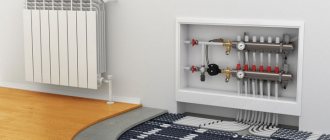
The Valtec Combi pump and mixing unit (Fig. 1) is designed to maintain a given coolant temperature in the secondary circuit by mixing from the return line.
Using this unit, it is also possible to hydraulically link an existing high-temperature heating system with a low-temperature underfloor heating circuit. In addition to the main control elements, the unit also includes the entire necessary set of service elements, such as air vents and drain valves (Fig. 2 and Table 1). Thermometers make it easy to monitor the operation of the unit without the use of additional devices and tools.
It is permissible to connect an unlimited number of underfloor heating branches to the Valtec Combi unit, provided that the total coolant flow rate for these branches is no more than 1.7 m3/h (28 l/min). This water flow corresponds to a total power of 10 kW at a design temperature difference of 5 °C and 20 kW at a design temperature difference of 10 °C. When connecting several branches of a heated floor to a unit, it is recommended to use Valtec VTc.594 or VTc.596 collector blocks. The unit does not include a pump, since the pump is selected based on the characteristics of a particular system. Any pump with an installation length of 180 mm (without bends) and a threaded connection for a 11/2″ union nut can be built into the unit.
The main adjustment elements of the pumping and mixing unit
1. Balancing valve of the secondary circuit (item 2 in the diagram, Fig. 2, Fig. 3). This valve ensures mixing of the coolant from the return collector of the heated floor with the coolant from the supply pipeline in the proportion necessary to maintain the set coolant temperature at the outlet of the Combi unit. The valve setting is changed using a hex wrench; to prevent accidental rotation during operation, the valve is secured with a clamping screw. The valve has a scale with valve capacity coefficient values from 0 to 5 m3/h.
Note: the flow coefficient kv is numerically equal to the coolant flow [m3/h] with a pressure drop across the valve of 1 bar.
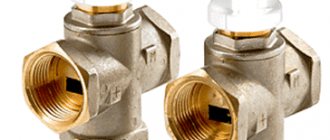
2. Balancing shut-off valve of the primary circuit (item 8 in Fig. 2, Fig. 4). Using this valve, the required amount of coolant is adjusted that will flow from the primary circuit to the unit (unit balancing). In addition, the valve can be used as a shut-off valve to completely shut off the flow. The valve has a micrometric adjustment screw, with which you can set the valve capacity. The valve is opened and closed using a hex key. The valve is equipped with a protective threaded plug. 3. Bypass valve (item 7 in the diagram, Fig. 2, Fig. 5). During operation of the heating system, a mode may arise when all control valves of the heated floor are closed. In this case, the pump will operate in a muted system (without coolant flow) and will quickly fail. In order to avoid such conditions, there is a bypass valve on the unit, which, when the valves of the underfloor heating system are completely closed, opens an additional bypass and allows the pump to circulate water through a small circuit without working “on a closed valve.”
The valve is activated by the pressure difference created by the pump. The pressure difference at which the valve opens is set by turning the regulator. There is a scale on the valve body with a pressure drop setting range from 0.2 to 0.6 bar. Pumps recommended for use in conjunction with the Valtec Combi unit are capable of developing a maximum pressure of 0.22 to 0.6 bar.
After the heating system is completely assembled, pressure tested and filled with water, it should be adjusted. The adjustment of the control unit is carried out together with the commissioning of the entire heating system. It is best to adjust the unit before starting to balance the system.
Algorithm for setting up the control unit
The mixing unit is configured in the following order.
1. Remove the thermal head (item 1 in the diagram, Fig. 2) or the servo drive from the thermostatic valve of the unit (Fig. 6). The thermostat drive is removed so that it does not affect the process of setting up the unit.
2. Set the bypass valve (item 7 in the diagram in Fig. 2) to the position of maximum pressure drop (0.6 bar), fig. 7. This is done in order to prevent possible valve activation during unit setup.
3. Adjust the balancing valve of the secondary circuit (item 2 in the diagram, Fig. 2). The required capacity of the balancing valve can be calculated using the formula:
where t1 is the temperature of the coolant in the supply pipeline of the primary circuit; t11 — coolant temperature on the supply pipeline of the secondary circuit; t12 — coolant temperature in the return pipeline (the same for both circuits); kvt is the control valve capacity coefficient, taken equal to 0.9. The resulting kv value is set on the valve (Fig. 8).
4. Set the pump to the required speed. To do this, you need to calculate the water flow in the secondary circuit and the pressure loss in the circuits after the unit using the formulas:
where Q is the sum of the thermal power of all loops connected to the mixing unit; 4187 - heat capacity of water [J/ (kg⋅°C)], and if another coolant is used, then the heat capacity should be taken from the technical passport of this coolant; t11 and t12 are the coolant temperatures on the supply and return pipelines of the secondary circuit, respectively.
The pressure loss in the design circuit of the heated floor (including collectors) can be obtained by performing a hydraulic calculation of the heated floor. To do this, it is recommended to use the Valtec.PRG calculation program, available for download on the Internet resource www.valtec.ru.
The pump speed is determined from the pump nomograms. To determine the pump speed, a point with the corresponding pressure and flow rate is marked on the graph. Next, the nearest curve located above this point is determined - it will correspond to the required speed. The speed is set by a switch on the pump.
5. Balance the heated floor loops. Before balancing, it is necessary to close the balancing shut-off valve of the primary circuit (item 8 in the diagram, Fig. 2). To do this, remove the valve plug and use a hex wrench to turn the valve counterclockwise until it stops (Fig. 9).
The task of balancing underfloor heating loops comes down to creating a calculated coolant flow rate in each loop and, as a result, uniform heating of the floor surface.
The loops are adjusted using balancing valves or flow regulators located on the manifolds. As a rule, VTc.594 or VTc.596 manifold blocks are connected to the Combi mixing unit. VTc.594 blocks are equipped with balancing valves on the supply manifold, and VTc.596 blocks are equipped with flow regulators with float rotameters. To simplify the setup of loops connected to the VTc.594 manifold, it is recommended to equip each loop with a VT.FLC15 linear rotameter.
Balancing the loops is carried out in the following order: balancing valves or flow regulators on all underfloor heating loops are opened to maximum. Start adjusting the flow rate from the loop in which the deviation of the actual flow rate from the design flow rate is maximum. The valve on this loop is “pressed” to the required flow. In the same way, you should adjust the flow rate in each of the underfloor heating loops.
If you have rotameters, it is enough to simply set the required flow rate on the rotameter scale [l/min] using a balancing valve or regulator (Fig. 10). If it is not possible to use a flow indicator, then you can adjust the loops approximately according to the heating of the floors or the temperature of the return coolant.
If during the balancing process it was not possible to obtain the required flow rate in the loops even with the valves open, this means that the hydraulic calculation was performed incorrectly and the pump should be switched to a higher speed.
If the Combi mixing unit serves only one circuit, then balancing is not required.
6. Adjust the balancing valve of the primary circuit (item 8 in the diagram, Fig. 2). The primary circuit valve is adjusted during the overall balancing of the heating system. The essence of balancing is to establish the design coolant flow in each circuit, branch, heating device, as well as in the primary circuit of the Combi unit.
If balancing of heating systems is performed incorrectly, the operation of individual sections of such a heating system will be incorrect.
When hydraulically calculating a heating system, a detailed piezometric graph is drawn up for the designed heating system. During the calculation, the required pressure loss at each balancing valve is determined. Next, the valve capacity is determined:
where V is the volumetric coolant flow rate, m3/h; Δp is the required pressure loss across the valve, bar.
After calculating the capacity according to the recommendations of the balancing valve manufacturers, the adjuster sets the design capacity value on each valve. Hydraulic calculations must be carried out by qualified specialists using standard methods or using special calculation programs, for example, Valtec.PRG.
The valve speed is set in the following order:
❏ before adjusting the valve, it must be in the fully closed position (the stem must be unscrewed counterclockwise until it stops);
❏ using a thin slotted screwdriver, tighten the adjusting screw until it stops and place a mark on the valve and on the screwdriver;
❏ according to the valve setting table, turn the screw the required number of turns - to fix the turns, use the marks on the valve and the screwdriver (according to the example given, you need to make 2 1/4 turns, Fig. 11);
❏ using a hex wrench, open the valve all the way, and the valve will open the number of turns by which the screwdriver was turned, and after setting the valve, you can open and close it using a hex wrench, the throughput setting will remain the same.
7. Setting the bypass valve (item 7 in the diagram, Fig. 2, Fig. 5). You can set the bypass valve in the following two ways:
❏ if the resistance of the most loaded branch of the heated floor is known, then this value should be set on the bypass valve;
❏ if the pressure loss on the most loaded branch is unknown, then the bypass valve setting can be determined from the pump characteristics, and the valve pressure value is set to 5–10% less than the maximum pump pressure at the selected speed (Fig. 12) - it is determined from the characteristics graph pump
The bypass valve should open when the pump approaches a critical point, when there is no water flow and the pump works only to build up pressure. The pressure in this mode can be determined from the pump characteristic.
8. Final stage. After setting up all the components of the Combi unit, the thermal head of the control valve should be installed in place if you plan to use it as the main body for regulating the temperature of the coolant. If the coolant is adjusted using a controller (for example, K200), then instead of a thermal head, a servo drive with analog control is mounted on the valve, and the controller’s coolant temperature sensor is installed in the socket under the thermostat. Don’t forget to replace the primary circuit balancing valve plug. After this, the unit is ready for operation.
We especially note that setting up heating systems is one of the most difficult engineering tasks in heat supply. The Valtec Combi pump and mixing unit makes this job much easier. This unit is a ready-made comprehensive solution for organizing a heated floor circuit in heating systems. A well-thought-out configuration of the unit allows you to eliminate errors when designing a particular system. The flexibility of setting up the Valtec Combi unit allows you to set up underfloor heating systems without the use of special devices.
Final debugging
Adjusting the mixing unit of a Valtek heated floor requires linking the equipment with other heating devices. The main task: to adjust the movement of coolant through each unit so that it corresponds to the project. If mistakes are made at this stage, some devices may not heat up enough, while others, on the contrary, will overheat. There are several ways to balance a Valtec underfloor heating manifold. The instructions for the equipment describe this process in detail.
Next, we have to configure the bypass valve. You can do this in one of two ways. When we know the resistance of the busiest branch, the same value is set. If the indicator is unknown, focus on the pump. In the latter case, the value for the valve should be 90-95% of the maximum pump pressure for the speed at which it is set. The instructions for Valtek water-heated floors also indicate these parameters.
The process ends with a system check. The task is to ensure that all branches are heated evenly and that the correct balance of temperatures of the liquid flowing through all pipelines is maintained. If you are sure that the mixing unit for the Valtec heated floor is configured correctly, you can put on the thermal head of the control valve, as well as other protective attachments. The equipment is now completely ready for use. As you can see, the process is not so complicated that it is necessary to resort to the help of professionals.
Warm floors from Valtek units are a high-quality and reliable system that will provide a comfortable climate in the room for many years. It's no secret that setting up heating is one of the most difficult engineering tasks. The slightest miscalculations at this stage can lead to unstable operation, resulting in user dissatisfaction and reduced equipment life. The operating principle of the Valtec underfloor heating mixing unit greatly simplifies the organization of the system. No special tools are required for installation, and the design diagram virtually eliminates the possibility of making a mistake.
Using drives
In addition to the thermostatic head, the valve can be controlled in other ways. The first of them is manual, when the depth of pressing of the rod is determined by turning the handle outside the body. Not the best option and is only suitable if the temperature of the water entering the pipes is constant. Another option is control using a servo and electric drive, receiving commands from the controller. To work together with different drives, another type of valve is used - rotary valves, whose device is shown in the figure:
This 3 outlet valve is very similar to a regular motorized ball valve
There is a certain similarity here with a ball valve, only the working rotary element has a different hole shape to allow coolant to flow in two directions at once. The operating principle here is simple: the axis rotates to the required angle, rotated by the drive. The latter is controlled by a controller that receives impulses from one or more sensors. Typically, valve actuators are installed in complex or automated heating systems with weather control.
Assembly of the mixing unit
When faced with such a seemingly difficult task, you first need to understand in detail the intricacies of this process. Below is an example of assembling a mixing unit with your own hands; the assembly will be made from metal components.
We will assemble it according to a scheme in which there is a thermostatic three-way mixing valve and a series connection of a circulation pump. To seal the seams, use flax tow and sealant paste; good reviews of Unipack paste.
You will need the following materials:
- Union nuts, American.
- Manual air vent.
- Nipples.
- Circulation pump.
- Thermometer.
- Check valve.
- Ball valve.
- Tees.
We are assembling on the basis of a three-way mixer of the ESBI thermostatic valve; the box indicates in which direction the water is mixed. The operating outlet temperature is 20-43 degrees Celsius, which meets the requirements for a heated floor system. This mixer already contains a thermostatic head, a temperature sensor and a temperature controller that allows you to set the temperature you need. On it itself, arrows indicate in which direction cold and hot water flows.
The next step is to purchase and install a circulation pump. It’s better not to skimp on it and buy a reliable one, since it will determine how evenly the heat will be distributed throughout the house and then the heating will be effective. After all, a pump that is economical in price means in 90% of cases its quick repair or replacement.
Wilo has proven itself well in this niche. Having picked it up, inspect it, determine in which direction it pumps liquid. Determine the direction of the drive axis; during installation, it should be located horizontally; this is one of the mandatory operating conditions for pumps that have a wet rotor installed in their design. Another prerequisite is that the switching box cannot be located under the pump.
If, nevertheless, it becomes this way for you, then rotate the upper element of the housing to which the box is connected 180 degrees. This can be done by using a hex wrench to unscrew the four screws that connect the two halves of the pump. Then carefully rotate the upper element relative to the lower pump element. Put everything back together and tighten the screws.
Photo of an example of a mixing unit for heated floors
The next thing we have to do is to install thermometers on the pipe where the supply takes place before the mixing process, then after the pump. Install the latest one at the outlet of the return manifold. Choose temperature sensors equipped with a probe that screws into central sockets. It would be advisable to verify each device.
Since in one chain they are subject to the same pressure, accordingly, their values should be the same. If possible, check with a reference device. If one of the devices has different readings, you can adjust this yourself. If you remove the cover, you will see a screw that you can use to adjust the readings.
So, the installation steps:
- Assemble the section from the primary supply to the mixing valve, connect the shut-off and ball valves and the tee under the temperature controller. Each of the four taps must be equipped with a union nut. This is done for ease of future maintenance.
- Connect the next outlet of the concentrate to the inlet pipe of the mixer with a three-way valve. Install a thermometer in the central socket of the tee.
- Install a bypass jumper, screw a coupling with an American connection to the second input. This is for ease of installation during maintenance.
- Then connect the tee to the jumper; one side should be facing the return of the system, and the other to the collector.
- The common return element includes one shut-off ball valve. There is no need to install a check valve, since most likely it will not be useful.
- Then assemble a parallel section. Install the temperature sensor by first screwing in the tee.
- Then it was time to assemble the element between the pump and the supply manifold. It includes a coupling with an American connection, a triple connecting element for the temperature regulator, an extension cord, and a shut-off valve.
- Install a ball valve near the manifold.
- Screw the coupling onto the outlet of the mixing valve.
- Well, the almost final stage is the installation of a circulation pump. Insert the rubber O-ring and tighten the nut on the inlet pipe of the pump.
- Screw and crimp the union nut on the other side in the same way. So the mixing unit for the heated floor has been assembled.
This was the final step, then place this element where it will be installed.
What regulates the bypass of the TIM JH-1036 mixing unit.
The mixing unit has a conditional mixing chamber through which the underfloor heating circuit and the boiler heating circuit pass.
Typically, a heated floor mixing unit has one adjustment parameter - the water temperature in the heated floor circuit. The TIM JH-1036 mixing unit also has some kind of bypass, and even adjustable. And this is not the bypass balancing bypass, which is triggered by excessive pressure developed by the pump.
The pressure balancing bypass can be seen in the photo - the rightmost personal belongings.
I need it because it is possible to block all heating directions of the heated floor as a result of automatic regulation. By the way, I still haven’t figured out how to regulate the balancing bypass TIM M307-4 - maybe someone can tell me.
As for the mixing chamber bypass, you can find the following graphic explanation of the operation of the mixing unit bypass:
Little is clear from these diagrams.
Moreover, it is not clear what the numbers on the scale mean and what the current value is tied to. All this can be found out only by holding the TIM JH-1036 mixing unit in your hands:
It turns out that the adjusting screw turns the cylinder, which has a slot that closes when turned. Through this slot, water can be pumped by a circulation pump, bypassing the conditional mixing chamber.
It should be taken into account that the sticker with a scale from 0 to 5 can be pasted arbitrarily.
The maximum opening of the slot (pictured above) corresponds to setting the adjusting screw to position 5 (pictured below).
The technological ledge on the mixing chamber body can be taken as a conventional point for reading the scale value. When the scale value is 0, the gap is maximally closed. In this position, all the water pumped by the circulation pump along the contours of the heated floor passes through the mixing chamber.
With the bypass completely closed, the thermal power of energy taken by the mixing unit from the heating system is maximum.
If the bypass is completely open, then part of the water circulates through the heating circuits without entering the mixing chamber - and the thermal power of extraction is minimal.
But in practice it turned out that not only thermal power is regulated by the bypass.
Features of the mixing unit operation
Any liquid heating system works according to the following principle:
- Heating element.
- Heating circuit, pipes through which coolant circulates.
- Devices regulating the coherence of the system.
Liquid heated by the boiler or from the central heating main enters the system. The central heating system supplies water at 60-80 degrees Celsius, while an autonomous heating boiler heats it up to 70-90 degrees. In accordance with sanitary requirements, the floor temperature should be in the range of 29-32 degrees; if these conditions are met, the microclimate in the house will be comfortable for humans.
To achieve these indicators, a liquid of 36-60 degrees enters the water floor. The layers of the floor absorb excess temperature, thereby achieving a comfortable temperature on the floor surface. To transport liquid of the required temperature into the water circuit, a mixing unit is needed, this is a kind of adjustment mechanism.
Technical characteristics of radiators
Competition in the radiator market is extremely high, so there are not many manufacturers producing and selling cast iron batteries on the domestic market.
Before purchasing, you should familiarize yourself with the technical characteristics of the most common cast iron heating radiators. This will allow you to choose exactly the products that are most suitable for the planned or existing heating system.
Manufacturers of cast iron batteries
If German batteries are particularly sophisticated, then the products produced by ChAZ are not inferior to them in their technical characteristics.
Moreover, the batteries of the Cheboksary Aggregate Plant are the best among Russian manufacturers . The main factories that offer cast iron batteries are:
- Adarad (Türkiye);
- Cheboksary Aggregate Plant (Russia);
- Viadrus (Czech Republic);
- Demrad (Türkiye);
- Minsk Heating Equipment Plant (Belarus);
- KIRAN (Ukraine);
- Konner (China).
There are many European manufacturers of cast iron radiators, but their products are not competitive. It has a high price, and the quality is comparable to domestic samples.
Devices for organizing heating in a vintage style are offered by a St. Petersburg manufacturer:
Overall dimensions of radiators
The sizes of radiators in the post-Soviet space were standardized. The distance between the center of the axes of the supply and discharge coolant pipes was 300 or 500 mm.
The depth of the sections and their width were not regulated and differed from one manufacturer to another. Most modern radiators are also adapted to these standards.
Cast iron radiators can be selected to any size required for placement under a window sill or in a wall niche
The most common model of cast iron batteries is MS-140. This is what stands in most Khrushchev and nine-story buildings built in the 60-80s of the last century.
The dimensions of its section are: center distance – 500 mm, total height – 588 mm, width – 93 mm, depth – 140 mm.
The wider the sections, the fewer of them are required to gain the required power, which means the number of potentially problematic joints is reduced.
The main goal of creating cast iron radiators with different dimensions is to enable the buyer to choose a model that best fits into the interior. Batteries with a total height of up to 400 mm, for example, fit perfectly into rooms with low window sills.
Appearance and structure of equipment
Almost all cast iron radiators are stacked. They are made of gray cast iron and consist of detachable sections that are connected using nipple bushings. This design allows you to form a solid battery of the required length and power. Paronite gaskets are placed between the sections.
Multi-column cast iron radiators are difficult to clean externally from dust, which significantly reduces the heat transfer of the batteries
In the horizontal plane between sections, water moves in only one direction. Vertically, the fluid flow occurs through one or more channels. With their number, the area of radiators and their power increases.
The disadvantage of multi-channel sections is their high cost and increased hydrodynamic resistance.
The classic "accordion" look of radiators is becoming a thing of the past. Due to the predominantly radiant method of heat transfer, manufacturers are seeking to increase the area of the battery façade, which results in a flatter appearance. An example is the Konner Modern500 model.
Radiators made of cast iron from the Konner Modern series, at a low cost, have a beautiful polished surface identical to aluminum panels
A number of imported models have decorative patterns on the surface, but the cost of such batteries is incomparably high.
The weight of cast iron sections is quite large. The need to maintain wall strength and maximum heating surface area does not allow engineers to greatly reduce the weight/power ratio. The weight of the section of the standard MS-140 model is 7.1 kg.
The unwinding of sections of cast iron radiators must be carried out gradually and synchronously from above and below, otherwise the threaded connection can be irreversibly damaged
The large mass of cast iron radiators also requires good fastenings. Batteries usually do not have special design elements for fixing to the wall. They are simply hung on special brackets, which are pushed into the spaces between the sections. There are also special feet for installing batteries on the floor.
Thermal power of devices
The power of radiator equipment is characterized by the ability to release thermal energy at the maximum operating temperature of the coolant. This indicator in cast iron radiators depends mainly on their surface area.
Depending on the model, the power can range from 80 to 200 W per section. These are passport values, which in real conditions can be much lower.
The recommended power of heating radiators is approximate. For regions with severe frosts, it may differ greatly from the standard
There is a classic formula for calculating the required power of a cast iron heating battery based on the volume of the room: for every 25-30 m3 radiators with a total capacity of 1 kW should be installed. If there are 2-3 external walls, this indicator should be adjusted towards increasing power. For more information on how to calculate the required number of batteries for heating, read this material.
To enhance heat transfer due to convection, some models of cast iron radiators are equipped with ribs between the columns. This design can increase the power of the section by 20-40%. You should remember the need to regularly clean such jumpers from dust.
Other equipment characteristics
When choosing radiators, you should pay attention to their other characteristics:
- maximum working pressure;
- coolant volume in the section;
- maximum coolant temperature.
All of the above indicators for cast iron batteries are higher than for aluminum and bimetallic counterparts. But the characteristics may differ for different models, which should be taken into account when selecting the components of a new heating system.
Models of the Minsk Heating Equipment Plant
Maximum settings are especially important when replacing batteries connected to a central heating system. When it is pressurized in the fall, excess pressure is supplied to the pipes, which can rupture unsuitable radiators.
This can result in flooding of both your own and the apartment located below, so special attention must be paid to the operating values of pressure and temperature of the coolant
Selection of pump and other system components
Selecting a pump is quite an important step; if you make the wrong choice, you may not achieve the desired results. Naturally, this choice should include several components, namely power, volume, how much energy it consumes and reliability. If you make your choice correctly, you will end up with a warm room and resource savings.
At the first stage, you need to calculate the required power of the pump group, if you have a small heating area, and therefore the pump needs a mini power. According to technical characteristics, they are divided into types with a wet or dry rotor. Power is defined as the total volume of coolant multiplied by three.
However, you also need to take into account such data as the amount of energy consumed, productivity (this is the amount of liquid that it passes through itself per unit of time). Also consider its operating pressure and maximum temperature.
Let's consider the productivity formula provided that the coolant is water:
Q= 0.86*Рн/(Tpr.t-Tobr.t), where -
Рн - heating circuit power;
Tobr.t - return circuit coolant temperature;
Tpr.t - inlet water temperature.
If it is assumed that there is more than one circuit, then the power is summed up, this total will be the required performance value. Power is a value that depends on the heating area; also take into account the climatic factor; if you have harsh winters, it is recommended to take a device with a safety margin of 20-25%.
As for the design of pumps, their selection is based on power; there is a division into devices with a wet rotor and a dry one. Wet ones are designed for small rooms, while dry ones are needed for heating large rooms.
When choosing a boiler, you should also take into account its power and throughput; often a separate boiler is purchased for this. When choosing pipes, pay attention to their wear resistance and ability to bend; it is better to give preference to stainless steel pipes, since they have a high thermal conductivity.
conclusions
The operation of a water heated floor pump is comparable to the functions of the heart in living organisms - it promotes the movement of coolant within the system, allowing the operating temperature of the pipes to be maintained in a normal state without excessive cooling.
Maintaining constant pressure and flow stabilizes the functioning of the heated floor and helps overcome the hydraulic resistance of pipelines of complex configuration and small cross-section.
A correctly selected circulation mode makes the system operate efficiently, economically and extends the service life of all elements of the water heated floor. Date: September 25, 2022
Adjustments and settings
How to set up a heated floor yourself? This question will arise before you as soon as everything is completed with its installation. Install all loops in the distribution manifold. The temperature of the incoming coolant to the collector and loops will be the same. While the output on the loops will be different, this is due to the different lengths of the circuit and different areas.
There are two methods to adjust the floor temperature. The first method is to regulate the fluid that enters the heating circuit. The next method is to regulate the temperature by stopping the circulation of coolant into the heating circuit.
Let's look at all the methods in more detail. One of the methods is to use when installing pipes operating at high temperatures up to 95 degrees. When using this method, a pump and a return outflow valve are installed on the supply, and a temperature sensor is installed on the return manifold.
A pump is connected through it, and a coolant flows into the underfloor heating system, the temperature of which reaches about 80 degrees Celsius. During circulation, the return circulation temperature gradually increases, the sensor is triggered and the supply of warm water is turned off. Then it goes into standby mode. Then the floor gradually gives up its temperature, the coolant cools down and starts all over again.
The next method is to install a pump on the supply, and in front of it a mixing valve; this can be replaced with a three-way valve. With this device, hot and cold water are mixed.
If you have a three-way distribution valve, you need to adjust it manually or using a servo drive. And the mixing valves adjust the temperature values according to preset values. To adjust the valve, you will need to take temperature measurements.
You can also adjust the temperature using the mixing module. They are expensive, however, they are the most effective.
Hydraulic leveling of water heated floors
We have a water heating system, which includes water heated floors, based on a pumping and mixing unit and a conventional manifold with or without flow meters. It is a reliable, safe, comfortable and well-managed underfloor heating system. In order for it to become such in reality, and not just on advertising brochures, it needs to be configured.
For a water floor in a private house, it is better to use collectors with flow meters; in this case, it will be much easier to manage the system. If you are reading this article, but you have a similar heated floor in an apartment or house with central heating, then pay attention to the maximum operating pressure of the collector you have chosen; usually for collectors with flow meters it is 6 bar. This may not be enough for a central system.
If you have servos on the collector that are controlled automatically, then they will regulate the coolant flow as necessary. However, it will be necessary to pre-set the flow in the circuits. If you have a collector without drives (in the vast majority of cases), then this setting is simply necessary.
The coolant flow through the circuit can be calculated using the formula:
Further, in order to obtain the required calculated coolant flow through the circuit, it is necessary to multiply the specific flow rate Gsp ((l/h)/m2) by the floor area S (m2) served by this circuit.
So, the simplest way to hydraulically level a heated floor is:
- calculate the water flow through each circuit by multiplying the floor area through which this circuit passes by 8.6; thus, we obtain the flow rate in l/h;
- turn on the underfloor heating pump, set it to first speed (for an average private house);
- set the thermal head or mixing valve handle to a position of approximately 30 o C;
- make sure that water circulates freely through the branches and air is expelled;
- adjust the kennel in such a way as to achieve the flow rates obtained in step 1 on each flow meter;
These actions will provide the so-called “pre-tuning”. If everything is calculated correctly, then it will be quite enough. But in fact, during operation, underfloor heating may need to be adjusted based on the feeling of comfort. When setting up, it is necessary to understand that the circuits are hydraulically interdependent; “screwing” one can increase the flow through the other. You also need to be prepared for the fact that the boiler pump and the heated floor pump will influence each other. This is not scary, but when the boiler pump turns on, it is impossible to adjust the heated floor; you need to wait until it stops.
Schemes and options for connecting mixing units
There are various connection options, almost all of them are homemade, since all calculations and needs of heating points are individual. They differ depending on the number of collectors and the number of circuits, so below are the most commonly used ones.
The node consists of:
- Adapter.
- Circulation pump.
- Ball valves.
- Threaded connection element.
- Futorka.
Futorka - threaded fitting - Barrel.
- Tees.
For an auto-adjustment system, the elements are slightly different:
- Mixing valve.
- Futorka.
- American women.
- Metal-plastic pipes.
- Connecting elements with internal thread.
- Nipple.
- Thermal head.
- Pump nuts.
- The pump itself.
- Knee.
- Extension cords.
- Knee.
- Thermal head sensor.
To connect multiple circuits, the following components are required:
Many people today install a heated floor system as additional heating. In apartments, as a rule, it is electric, but for private cottages it is more profitable to install a water floor. To equalize the temperature supplied to the hot coolant input, it is necessary to install an additional element, which is a mixing unit for a heated floor.
Calculation instructions
In order to correctly develop a project for laying a heated floor, you will need a preliminary calculation of the main indicators, focusing on their average values.
Do-it-yourself installation of water heated floors
Various factors have to be taken into account, including the role of the water floor as the main type of heating or its use as an additional heat source. Since detailed calculations for independent implementation are a complex process, in practice average parameters are used.
Valtec mixing unit connection diagram
- The rated power has limits of 90 - 150 W/m2. Higher values are selected for rooms with high humidity levels.
- When calculating the laying step, you need to focus on the range of 15–30 cm. The specific heating power is in inverse proportion to this indicator. That is, the larger the step, the less power.
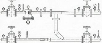
Thermomechanical diagram of a pumping and mixing unit - Despite the fact that with a large diameter of pipes, a larger amount of coolant passes through them, the limiter of this indicator is the thickness of the screed, which is not recommended to be too large, so as not to create excessive load on the floor. Therefore, Valtec pipes are taken into account, made of modern cross-linked polyethylene with an anti-diffusion coating, with a diameter of 16 to 20 mm, and Valtec press fittings are used as connecting parts.
Once the key parameters have been determined, a diagram can be developed in which the most efficient pipe laying is determined on an exact scale. After this, their total length is calculated. At the same time, it is thought through where the pumping and mixing unit and control elements will be located.
Why do you need a thermal mixer?
The scheme of a combined heating system of a private house may consist of:
- Heating boiler;
- Collector node;
- Heated floor contours;
- Radiator circuits.
The temperature of the water heated by the boiler is 75-95 ° C, while sanitary standards set the figure at 31 ° C as the maximum comfortable temperature of the floor surface for walking on it barefoot. Therefore, direct flow of water into floor circuits is unacceptable. This problem is solved by installing a mixing unit.
The thermal mixer is used to mix hot and already cooled water from a water floor heating system. Thanks to this, the heating circuit functions without deviations.
How the system works
Select the bypass adjustment value 0-5 depending on the situation.
Using the example of these two mixers, we can now show the difference between the different bypass adjustments of the TIM JH-1036 mixing unit.
Bypass setting value is 0.
The first mixer operates in conditions where the bottleneck of the system is the heat supply from the system.
It is connected like a radiator in a one-pipe system.
Just in case, I made a thickening at the connection section from 25 to 32 diameters and installed a tap, since I doubted that a sufficient amount of water would flow in and provide sufficient power.
This local heating subsystem is built, of course, on one mixing unit without a collector group.
There should be no problems with circulation along one circuit.
Therefore, we set the value of the bypass adjustment bolt to 0.
We make the circulation through the heated floor circuit minimal, and the circulation through the mixing chamber maximum.
It was shown above that here the mixer pump will help the circulation through the heating system a little more.
Bypass setting value 5.
In this case, on the contrary, the heated floor mixer is connected directly to the boiler in parallel to a single-pipe system with batteries.
There are no problems with supplying the required thermal power to the mixer.
But turning 4 heating circuits will not be as easy as one.
Therefore, we set the bypass adjustment value to 5.
We make the circulation through the heated floor circuit maximum, and the circulation through the mixing chamber minimal.
In addition, with such an installation we further limit the influence of this circulation pump on the main system.
Passport TIM TIM JH-1036 pasport-smesitelnogo-uzla-tim-jh-1036.pdf
Twin passport Profactor PF MB 841 pasport-mb_841_nasosno_smesitelnyj_uzel.pdf
- How I adapted the TIM JH-1036 mixing unit for underfloor heating. How much does it cost and where to buy equipment for a TIM warm field - Estimate
- How to set up the bypass of the TIM JH-1036 mixing unit
How does the mixing unit work?
Before being distributed into the collector, the hot coolant enters the mixing system, where a thermostat measures its temperature. If the value exceeds the permissible value, the safety valve opens and prevents cold and hot water. When the liquid reaches the desired temperature, the valve stops supplying hot water.
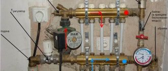
Mixing unit diagram
As a rule, the mixing unit not only provides a comfortable temperature regime, but also serves to raise the pressure level in the circuit, which improves the circulation of the coolant. The mixing unit diagram includes:
- Safety valve;
- Circulation pump;
- Bypass;
- Air outlets;
- Valves for stable operation of circuits (shut-off, drainage).
The mixing unit diagram can have a different design. Schemes with two- and three-way valves are more popular.
Diagram with two-way valve
A thermostat equipped with an infrared sensor is installed on the two-way (supply) valve, which measures the temperature of the liquid entering the heated floors. The water in the mixing system moves in a circle, and the fuse head regulates the valve that opens or closes the passage of hot water. This is how the process of mixing liquids of different temperatures occurs.
Three-way valve in the mixing circuit
The three-way valve is a universal equipment. It performs the functions of both a bypass valve and a bypass. Its peculiarity is that hot water interferes with the return flow inside the housing. This type of unit is equipped with servos, thermostats, and weather-dependent controllers. The latter are capable of checking the temperature outside every 20 seconds. If the temperature of the water that enters the underfloor heating system does not correspond to the desired temperature, the valve automatically turns 45° in one direction or another.
The three-way design, however, is imperfect and has its drawbacks:
- Presence of excess pressure;
- Possibility of hot water inlet;
- Large throughput, leading to significant fluctuations in coolant temperature.
Sudden changes in pressure and temperature can lead to rupture of underfloor heating pipes.
Two pumping and mixing units for underfloor heating in one heating system.
I ended up with two underfloor heating mixers in one heating system.
I made one right away at the first stage of repair and installed it temporarily.
So far, this mixer has controlled one branch of the heated floor. Then he intended to move it after the renovation was completed in other rooms. I laid pipes in the floor to connect this branch to the mixer in a new location.
But nothing is more permanent than temporary.
And in a new location he installed another similar mixer.
Someday I will remove the first mixing unit - the manifold of the second mixing unit has fittings for connecting this branch and the pipes have already been laid.
Please note that the mixer in the first photo is not capable of providing a coolant supply temperature of more than 25 degrees when the temperature set on the boiler is 50 degrees. The photo shows a coolant temperature of 30 degrees, achieved when the boiler temperature is 60 degrees and the thermostatic mixer head is set to 40 degrees
The photo shows a coolant temperature of 30 degrees, achieved when the boiler temperature is 60 degrees and the thermostatic mixer head is set to 40 degrees.
This is understandable with such a connection.
The paradox is that this (25 degrees) is enough to relatively quickly heat the room by a couple of degrees, maintaining the set temperature.
How to set up a mixing unit?
Connecting the mixing units is quite simple, so installation can be done with your own hands if you have instructions. The first thing to do is choose a location for the mixing unit.
If the parts of the water floor are connected through flexible pipes, then the mixing unit is rigidly mounted on the wall. The parts of the mixing unit must be freely accessible.
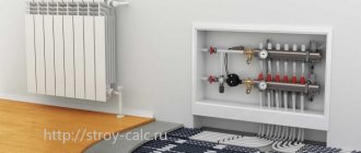
Manifold cabinet and its equipment
It is imperative to take into account the type of material from which the pipes are made. They must withstand the temperature of the incoming coolant. If a water-glycol solution is used, galvanized pipes will not work.
After installation, the mixing system is connected to the coolant supply and return pipes and pressure, temperature and flow sensors are installed. These elements are either supplied with the unit or assembled independently. After this, the thermal mixer is connected to the outlet pipes of the heating circuit.
Connection diagram for mixing unit
Before connecting the circulation pump, grounding must be done. Optimal pressure loss parameters are ensured using a balancing valve on the bypass. In this case, losses in the check valve are taken into account.
If the heating system is single-pipe, the bypass must always be in the open position. Then the hot water will flow in parts to the radiators. In a two-pipe circuit, the bypass is closed. When the entire structure is assembled, it is connected to the circuits using fittings.
Installation algorithm
After the preliminary calculation of all components has been completed, the actual installation of the heated floor begins, which involves going through several stages.
Scheme of water floor heating
- Installation at a pre-selected location of the manifold cabinet. It contains a module consisting of a collector block and a pumping and mixing unit with ball valves, through which the connection to the high-temperature circuit will be made.
- Preparing the floor plane. If there are significant irregularities, measures are taken to eliminate them. The most effective option is a rough screed. Connection diagram of the pumping and mixing unit to the heated floor
- Fixation around the perimeter of a damper tape, which serves as an element that compensates for the possible expansion of the screed that occurs when it is heated. It is attached to the walls so that after finishing the excess remains, which is cut off before installing the plinth.
- Thermal insulation equipment by laying polystyrene foam boards with mounting bosses on a leveled floor, under which waterproofing is laid if necessary.
- A previously developed diagram serves as a guide for the subsequent layout of pipes.
Features of setting up a Valtec manifold without flow meters
If the manifold is not equipped with flow meters, but only with valves, you will have to set the flow rate by touch. This is not figurative, but literally. Knowing the length of each circuit, we open the flow to the maximum on the longest one. We screw the rest approximately. You can count the number of valve revolutions and focus on them.
Manifold for underfloor heating without flow meters
Next, we turn on the heating and wait until the floor warms up. If you have a thermometer, measure the floor temperature in the operating area of each circuit. There is no thermometer - we feel and compare sensations. Based on the results, we adjust the position of the valves and wait again for several hours. We continue this way until we are satisfied with the result. In principle, a Valtec manifold with valves without a flow meter is not that difficult to configure.
Evaluating collector settings based on return temperature
This check is based on the fact that with a correctly adjusted flow rate, the return temperature on all circuits should be the same. To set up or check this type, you need special thermometers. They are installed on the return pipeline between the manifold inlet and the pipe.
You can adjust the collector using a return thermometer
The temperature of the longest circuit is taken as a reference - all the others are adjusted to it. Only the adjustment results will need to be corrected after a few hours. When the floor heated by adjustable circuits warms up or cools down (depending on the adjustment) and the temperature in the return pipe changes again. It will take several such adjustments until the difference becomes insignificant.
Water-based types of heated floors continue to improve, remaining popular among consumers. One of the recognized leaders is the Italian company Valtec.
VALTEC mixing unit for heated floors
Setting up manifolds with tuning flow meters
Preliminary adjustment of underfloor heating collectors is necessary and important. Even if the system has thermostats, controllers and other automation. If you entrust the adjustment to automation, after a while all flows will be as open as possible. So before starting the system, we are setting up the collector. Adjust the flow rate on a cold system without turning on the boiler. Heating is started after setting the flow rates in the loops - to check the temperature.
What is a flow meter and its design
Flow meters are used for the initial setting of flows, which is easier, more accurate and faster. In addition, during operation they allow you to evaluate the current flow rate in relation to the one set during setup. To understand the mechanics of adjustment, you need to know how the flow meter is designed and how it works. It is a hollow body with a poppet valve, which is supported by a spring. The spring is calibrated. Its top is formed into a transparent cone with a scale.
How does the Valtek flow meter work?
In order to be able to navigate by the flow values and, in fact, regulate it, a flow indicator is attached to the spring. For supply-mounted flowmeters, the default flow indicator is mounted on the top of the housing. In this position, it points to “0” and the flow is blocked (as in the photo above). If flowmeters are designed for installation on a return manifold, the flow indicator is located at the bottom.
There are two types of flow meters - with and without fixing the position of the adjusting sleeve. The first ones are more reliable, since the settings are not lost, which can happen with regular ones. But they are more expensive. And since the collector unit itself is not cheap, flow meters are often installed without fixation.
How to set the flow on a flow meter
The scale has marks and numbers from 0 to 5. The number indicates the strength of the flow - this is the speed of movement of the coolant in meters per second (m/s). The flow adjustment procedure is as follows:
Aligning the flow meter with a fixing ring
Aligning the flow meter without a lock
So, one by one we set the flow meters of each loop of the heated floor. As you understand, without the fixing sleeve there are slightly fewer steps. Please note: it is better not to skip the step with setting zero. This doesn't take much time, but allows you to check the calibration.
Method of adjusting floor heating flow meters
If you do everything according to the rules, you should have a thermal engineering calculation that indicates the flows in each loop. Do you have a plan? Then set the values according to the plan. If not, we will act based on the size of the contours. Provided that pipes of the same cross-section are laid, it will be necessary to change the flow rate based on the required heat transfer. But in this case, it is necessary to know the length of the pipe in each loop.
Let's look at an example. Let us have four circuits: 90 m, two 75 m and 50 m. The procedure for adjusting the flow meters of the Valtek collector is as follows:
- On the longest loop, 90 m long, we open the flow meter completely (if maximum flow is needed) or set the value that is required. Let us assume that for this case the maximum flow rate is 5 m/s. To do this, lower the flow indicator to the very bottom. There is a sign there for 5 m/s.
With the same length, the flows can be different. Depends on requirements (main heating or additional heating) or floor covering
If the flow on the longest loop should be below the maximum possible, set it to the required value (at least 3 m/s, at least 2 m/s). We recalculate the rest using this flow value.
Next, turn on the boiler and check how correctly the collector is configured. With the same length and the same flow rate, it may turn out that one circuit heats much better. This is due to a different installation scheme. A circuit that heats less well most likely has more bends or they are steeper. This increases hydraulic resistance, which reduces the speed of coolant movement. This means less heat is transferred. The solution is to increase the flow rate a little and see the results.
Functionality
The Combi unit design includes the following service elements:
- drain valves;
- air vents;
- thermometers.
Operating principle of the Combi unit
The following organs are used to adjust the unit:
It is permissible to connect an unlimited number of heated floor branches with a total power of no more than 20 kW to the VALTEC COMBIMIX node
- a balancing valve on the secondary circuit, which ensures mixing in the required proportion of coolants from the supply and return pipelines to ensure the standard temperature;
- balancing shut-off valve on the primary circuit, responsible for supplying the required amount of hot water to the unit. It allows you to completely shut off the flow if necessary;
- a bypass valve that allows you to open an additional bypass to ensure the pump operates in a situation where all control valves are closed.
The connection diagram has been developed taking into account the possibility of connecting to the pumping and mixing unit the required number of floor heating branches with a total water consumption not exceeding 1.7 m 3 /h. The calculation shows that a similar amount of coolant flow with a temperature difference of 5°C corresponds to a power of 10 kW.
Three ways to adjust flow meters
The microclimate in the room and the uniformity of floor heating in different areas depend on the correct adjustment of these devices. In addition, by adjusting flow meters, it is possible to significantly reduce energy losses for heating buildings. And this is very important, given the current cost of electricity and gas.
Inexperienced installers believe that in order for the temperature of the circuits to be the same, the readings of the flow meters must also be at the same level and thus they are adjusted.
Inexperienced installers set everything up “on a ruler”, believing that the flow rate is the same everywhere
This is wrong, if this were actually the case, then why would we need devices that are quite complex from an engineering point of view? Pipes of different lengths must receive different volumes of coolant, only in this case their temperature will be the same. Accordingly, the flow meter readings on each loop are individual.
Flow meter readings on each loop are individual
There are several ways to configure flow meters.
First way
The most correct, fast and accurate. The adjustment must be made taking into account the parameters of the hydraulic resistance of each circuit. For this purpose, VALTEC has developed a special program, which can be used on the website of the official representative. Working with the program is very simple, fill out all the tables with your data and eventually get the resistance of each loop. The only inconvenience is that the results are given in kilograms per second, while the scale on the flow meter is in liters per minute. In order to use the flow meter scale, you need to multiply the obtained data by 60. Set the flow meter scale for each loop according to the obtained values in turn.
Hydraulic calculation program
Second way
It is used in cases where the cheapest manifold without flow meters with a scale was purchased. Instead, conventional control valves are installed; the flow rate is changed by turning them clockwise or counterclockwise.
Manifold with control valves
It is recommended to install the flow meter on the “return”; they are not adjustable, but do have a scale. Turn the tuning valve and monitor the actual flow rates using the return scale.
Flow meter installation diagram
If for some reason it is impossible to install flow meters on the “return”, then you should use the table supplied with the manifold. It indicates the change in the amount of coolant depending on the number of turns of the control valve. The calculation program gives the values as percentages; you need to find this parameter in the table, so you can find out how many turns to tighten or unscrew the valve. This method is more complicated, but it allows you to save money when purchasing a collector.
The required values in the table are marked with a tick
Third way
In scientific terms it is called empirical, but in simple terms it is called “by eye”. It requires knowing the actual length of each loop. Adjustment should begin with the longest one.
Loop lengths
Open the valve regulating this loop to maximum. Next, make calculations as a percentage of how much each of the remaining loops differs from the longest one and reduce the clearance of the control valve by the same percentage. This is a preliminary adjustment; later adjustments must be made depending on the actual temperature of the loops. The process may take several days; the floor heating system is very inert and it is impossible to immediately notice a change in its temperature.
The end result is to achieve the same coolant temperature at the return of each loop.
To measure, you can use a clip-on thermometer or a more modern pyrometer