VALTEC SrL was founded in Italy in 2002 and specializes in the production of equipment for thermal systems operating in difficult conditions. Currently, it is highly respected among consumers in various countries, including Russia. In terms of price, it is considered affordable for most users and fully meets European quality standards.
VALTEC
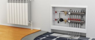
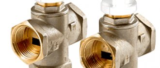
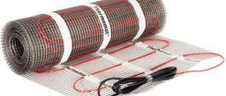
Valtec underfloor heating manifold with rotameters
The parts are made of CW617N brass and AISI 301 stainless steel. The manifolds have adjustment and shut-off valves, drain valves, and automatic air vents. All seals are made using EPDM rings, the standard for connecting Euroconus pipe loops. Some models have additional equipment that allows you to fully automate the operation of the devices. The number of outlets ranges from 2 to 12, diameters 1″ and 1 1/4″. The warranty on all company equipment is 7 years, maximum operating temperature is +120°C, optimal pressure is 10 Bar.
Pros of the Valtec system
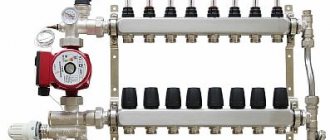
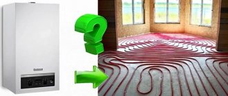
Specification of a Valtec mixing unit for underfloor heating
Before starting installation and selecting a mixing unit for Valtec underfloor heating, it is necessary to analyze the advantages of this type of water circuit.
- Thanks to high-quality materials and durable fasteners, reliable operation is ensured.
- Developed in the form of modules, the components fit together precisely, eliminating the risk of leaks.
- The manufacturer has provided for the production of related materials necessary for thermal and waterproofing equipment.
From the history of the company
Many online sources write that the birthplace of the Valtek brand is Italy, but this is far from the case. The idea of developing and releasing this brand belongs equally to both Russian and Italian specialists.
Initially, the company supplied to the market only shut-off and control valves, water supply and heating systems that best suited Russian operating conditions.
Currently, Valtek equipment and almost all components for water underfloor heating systems supplied to the market are manufactured in China. The company’s specialists closely monitor the quality of the equipment produced, checking it for compliance with domestic and European norms and quality standards.
Calculation instructions
In order to correctly develop a project for laying a heated floor, you will need a preliminary calculation of the main indicators, focusing on their average values.
Do-it-yourself installation of water heated floors
Various factors have to be taken into account, including the role of the water floor as the main type of heating or its use as an additional heat source. Since detailed calculations for independent implementation are a complex process, in practice average parameters are used.
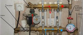
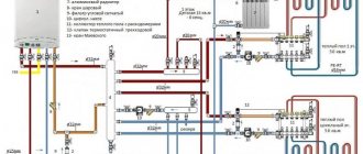
Valtec mixing unit connection diagram
- The rated power has limits of 90 - 150 W/m2. Higher values are selected for rooms with high humidity levels.
- When calculating the laying step, you need to focus on the range of 15–30 cm. The specific heating power is in inverse proportion to this indicator. That is, the larger the step, the less power.
Thermomechanical diagram of a pumping and mixing unit - Despite the fact that with a large diameter of pipes, a larger amount of coolant passes through them, the limiter of this indicator is the thickness of the screed, which is not recommended to be too large, so as not to create excessive load on the floor. Therefore, Valtec pipes are taken into account, made of modern cross-linked polyethylene with an anti-diffusion coating, with a diameter of 16 to 20 mm, and Valtec press fittings are used as connecting parts.
Once the key parameters have been determined, a diagram can be developed in which the most efficient pipe laying is determined on an exact scale. After this, their total length is calculated. At the same time, it is thought through where the pumping and mixing unit and control elements will be located.
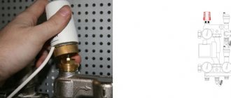
Manual adjustment of coolant temperature
How you adjust the temperature will depend entirely on the equipment you are using. For example, if a system with a temperature controller and a servo drive is installed, then the setup is carried out according to the instructions from the manufacturer of this device. In this case, the adjustment is performed automatically. Now let's look at the manual method of setting the temperature using thermal heads.
Thermal heads can be installed both on the supply and return side of the coolant.
First of all, the system up to the heated floor must be completely filled with coolant and freed from air. But it is important not to rush here, otherwise air jams may form. If the connection was made from the boiler, then before starting water into the heating circuits, turn off all taps. Afterwards, open the supply/return loop on one loop, filling it with coolant. The air should come out of it through the air vent. Now turn on the circulation pump so that the coolant begins to move in this loop. At the same time, turn the temperature on the boiler to 35°. To the touch you should feel that hot water is flowing in the return and supply in the heating circuit. If everything works properly, close this loop and open a new one. Using this method, you pump and check each loop of the heating circuit. When you have configured each circuit, you open all the taps and adjust the required temperature by touch. In some loops the faucet will need to be opened completely, while in others it is enough to open it slightly.
The coolant temperature in each circuit may be different. There are several reasons for this, such as the length of the loop. The shorter the circuit, the faster it warms up and vice versa.
Thus, manual temperature adjustment is carried out. It is enough to do it once a year. But here it is important to take into account the nuance. The underfloor heating system is inertial. What does this mean in practice? If you make changes to one of the hinges, you will have to wait several hours to notice a noticeable change in the temperature inside the room.
Key characteristics of the mixing unit
In order for the installed water circuit to function effectively, it is necessary to correctly calculate the entire system and correctly install the mixing unit for the Valtec heated floor in accordance with the provisions reflected in the instructions included with the kit.
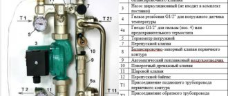
Connection diagram of the mixing unit to different types of heating
Parameters of the pumping and mixing unit:
- the cross-section of the pipes is ¾ inch, the collectors are 1 inch;
- the design contains 12 pipes;
- the pumping system is 18 cm long;
- the temperature of the heated water in the system is maintained up to 90°C;
- maximum pressure value – 10 bar;
- throughput – 2.75 m3/h. Specification of Valtec pumping and mixing unit
The pipes have an external thread with a Eurocone connection.
Pumping and mixing unit for heated floors
[ads-mob-1][ads-pc-1]
Flowmeter functionality
A rotameter or, to give a full definition to this unit, a float rotameter, at first glance, is a common mechanical device. The design of the product is based on a plastic case (there are models made of brass), inside of which there is a polypropylene float. The body is equipped with a transparent bulb on which a marking scale is applied. The movement of the float up and down inside the device indicates a certain value on the scale, by which one can judge the volume of coolant circulating in the pipeline system - whether it is enough for the full operation of the heating circuits.
Traditional flow meter for underfloor heating manifold in various versions: on the left - in a plastic case, on the right - in brass.
From a theoretical point of view, the heating system can operate without this device. In this case, you will have to manually adjust the volume of water entering the circuit, based on your personal feelings when the air temperature in the room changes.
Note: by the sound of the operating pump and the intensity of heating of the heated floor, one can judge the degree of completeness of the supply of hot coolant to all heating circuits.
Refusing to use a flow meter when installing heated floors is fraught with the following problems:
- individual circuits of the water floor will be supplied with coolant without taking into account the characteristics of the room, as a result of which the temperature values of the floor surface of heated rooms will differ;
- the energy consumption used to operate heating devices (electricity or gas) will be increased.
For example, you plan to heat the bathroom and children's room at the same time. An autonomous gas boiler will heat water for the bathroom and nursery in the same way, at the same temperature. However, the bathroom is smaller in area and will require less boiler water to heat it than to supply a heated floor in a nursery. You can achieve optimal supply of coolant to heated floors in each room using a flow meter. Consequently, due to the operation of this device, it will be possible to achieve individual temperature values for comfort in the bathroom and children's room.
Assessing the operation and principle of operation of the device, the following conclusions can be drawn:
- the device operates completely autonomously, without requiring additional power sources;
- the operating principle of the flow meter allows you to create optimal coolant flow for heating circuits, significantly reducing the energy consumption of heating devices;
- the design of the device provides visual control over the amount of water in the pipelines;
- the collector together with flow meters for underfloor heating significantly facilitates control over the operation of the entire system, is easy to install and unpretentious to maintain.
Important! Installation of the device is carried out strictly in a vertical position, simply screwing the device into a special socket of the collector. The device is fixed using a union nut.
Note: when installing a heated floor, try to achieve the same length of heat pipes for all water circuits - despite possible differences in configuration, this significantly simplifies the adjustment of the entire heating system and allows you to achieve optimal temperature parameters.
Functionality
The main purpose of the pumping and mixing unit is to stabilize the temperature of the coolant when entering the water circuit by using water from the return line for mixing. This ensures optimal functioning of the heated floor without overheating.
The Combi unit design includes the following service elements:
- drain valves;
- air vents;
- thermometers. Operating principle of the Combi unit
The following organs are used to adjust the unit:
It is permissible to connect an unlimited number of heated floor branches with a total power of no more than 20 kW to the VALTEC COMBIMIX node
- a balancing valve on the secondary circuit, which ensures mixing in the required proportion of coolants from the supply and return pipelines to ensure the standard temperature;
- balancing shut-off valve on the primary circuit, responsible for supplying the required amount of hot water to the unit. It allows you to completely shut off the flow if necessary;
- a bypass valve that allows you to open an additional bypass to ensure the pump operates in a situation where all control valves are closed.
The connection diagram has been developed taking into account the possibility of connecting to the pumping and mixing unit the required number of floor heating branches with a total water consumption not exceeding 1.7 m3/h. The calculation shows that a similar amount of coolant flow with a temperature difference of 5°C corresponds to a power of 10 kW.
In the case of connecting several branches to the mixing unit, it is advisable to select collector blocks from the Valtec line with the designation VTc.594, as well as VTc.596.
Simplified diagram of a heated floor collector
The simplest comb circuit consists of two circuits. For the manufacture of the distribution system, brass or stainless steel is used - two materials with high resistance to the aggressive effects of hot water. The comb must be positioned strictly vertically on the wall to ensure the efficiency of all components and allow the coolant to be evenly distributed.
The shut-off valves installed in each circuit may have a manual or automatic opening system using electromechanical actuators. In the system we are considering, as a rule, manual ones are used.
With the help of these valves, one of which is installed at the inlet and the other at the outlet, the supply of hot water is controlled. To regulate the fluid flow between circuits located, say, in adjacent rooms, so-called balancing valves are installed in the return ridge.
Installation algorithm
After the preliminary calculation of all components has been completed, the actual installation of the heated floor begins, which involves going through several stages.
Scheme of water floor heating
- Installation at a pre-selected location of the manifold cabinet. It contains a module consisting of a collector block and a pumping and mixing unit with ball valves, through which the connection to the high-temperature circuit will be made.
- Preparing the floor plane. If there are significant irregularities, measures are taken to eliminate them. The most effective option is a rough screed.
Connection diagram of the pumping and mixing unit to the heated floor - Fixation around the perimeter of a damper tape, which serves as an element that compensates for the possible expansion of the screed that occurs when it is heated. It is attached to the walls so that after finishing the excess remains, which is cut off before installing the plinth.
- Thermal insulation equipment by laying polystyrene foam boards with mounting bosses on a leveled floor, under which waterproofing is laid if necessary.
- A previously developed diagram serves as a guide for the subsequent layout of pipes.
Advantages
Like all Valtek products, the collector has a number of positive distinctive characteristics that lead to increased interest in them from consumers:
Collector connection diagram
- thanks to factory assembly, the entire manifold block during the production process undergoes multi-level repeated testing for compliance with safety and quality requirements;
- products supplied to Russian consumers are fully adapted to the relevant conditions;
- The purchased Valtec manifold has all the necessary certificates and technical data sheet.
The collector pipe is made of high quality AISI 304 stainless steel.
Settings
To connect pipes to distribution manifolds, a pipe cutter is used to cut the required length, a calibrator, a chamfer and a compression fitting. It is difficult to carry out detailed calculations at home, so be sure to study the instructions, which detail the settings of the pumping and mixing unit in a certain sequence.
- The thermal head is removed.
- For a balancing valve on the secondary circuit, the capacity is calculated using the formula. Two mixing unit options
kνb = kνt {[(t1 – t12) / (t11 – t12)] – 1},
where kνt – coefficient = 0.9 valve capacity;
t1 – supply water temperature of the primary circuit, °C;
t11 – temperature of the secondary circuit at the coolant supply, °C;
t12 – return pipeline water temperature, °C.
The calculated kνb value must be set on the valve.
- Setting the desired operating mode of the bypass valve when setting the maximum pressure difference to 0.6 bar.
- In order for the heated floor to function effectively, the required pump speed is adjusted. To do this, it is necessary to determine the value of the coolant flow rate in the secondary circuit system, as well as the pressure loss that appears in the circuits located after the unit. Equipment for Valtec mixing unit
Flow rate G2 (kg/s) is determined by the formula:
G2 = Q / [4187 • (t11 – t12)],
where Q is the total thermal power of the water circuit connected to the mixing unit, J/s;
4187 [J/(kg•°С)] – heat capacity of water.
To calculate pressure losses, a special hydraulic calculation program is used. To determine the pump speed, which is set using a switch, according to the calculated indicators, a nomogram is used, which is in the instructions attached to the heated floor design.
Connection diagram for heated floor circuits
- Operations are being performed to adjust the balancing valve on the primary circuit.
- The thermostat sets the temperature required for comfortable heating.
- A trial run of the system is being carried out.
If there are no leaks, all that remains is to make a concrete screed, and after it has completely hardened, lay the flooring. [ads-pc-2][ads-mob-2]
Optimal design of the collector group
The optimal design is considered to be a manifold group in which the supply manifold is equipped with a rotameter, and a thermostat is installed on the return manifold. Such a system will allow the required amount of coolant to be directed to each circuit, and the return manifold of such a system will open and close the circuits as the water cools.
It is also worth noting that the system can be improved with an automatic air vent, which is installed on the supply manifold; in turn, it should be connected to a bypass with a bypass valve.
It will work like this:
- Air vents will remove air from the system that interferes with its normal operation;
- If it gets warmer outside, the thermostats will close the circuits, and the bypass valve will reduce the increased pressure inside the system.
Speaking about how a heated floor flow meter works, it is worth making an amendment: there are three types of rotameters:
- The measuring rotameter is installed together with a valve, which is adjusted independently, depending on the measured readings;
- The regulating rotameter controls the amount of incoming coolant;
- The third type combines the previous two, but it also has an increased price.