A mixing unit or manifold for a heated floor is installed to regulate the circulation of the coolant and the level of its heating. In addition to its main function, this device helps measure pressure in the heating system, controls the correct supply of coolant and eliminates excess air from the heating circuit. If water-type heated floors are installed in several rooms, it will not be possible to do without such a device. It is worth studying in advance the types of devices and the principles of their operation in order to make the right choice.
The principle of operation of the collector for heated floors
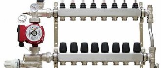
Manifold for underfloor heating
The mixing unit helps to supply coolant without the need to connect to the common manifold of the boiler room. A standard device of this type has a simple structure, is a group of several devices and can operate using a two-way or three-way valve. If the heating system is of a mixed type, such a unit is supplemented with a circulation pump.
The second pump is needed to cover all loops of the floor covering, while the first is responsible for the operation of the radiators. To decide on the selection of a valve, you need to first calculate the throughput for the water-heated floor circuits and find out the temperature limits for the coolant. For the middle and southern zone, a lower limit of up to 30 degrees or lower is sufficient, for the northern zone - from 35 degrees.
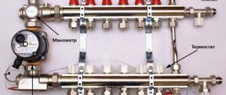
Mixing unit structure
The mixing group for heated floors can be built on the basis of a two-way or three-way valve. If the heating system is mixed - with radiators and heated floors, then the unit also contains a circulation pump. Even if the boiler has its own circulation system, it will not be able to “push through” all the loops of the heated floor. That's why they put the second one. And the one on the boiler runs the radiators. In this case, this group is sometimes called a pumping and mixing unit.
Diagram of a three-way valve
A three-way valve is a device that mixes two streams of water. In this case, it is heated supply water and colder water from the return pipeline.
Operating principle of three-way valve
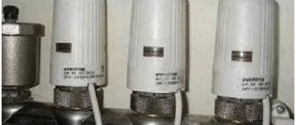
A movable control sector is installed inside this valve, which regulates the intensity of the flow of colder water. This sector can be controlled by a thermostat, manual or electronic thermostat.
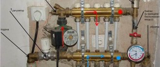
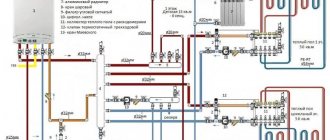
The diagram of the mixing unit on a three-way valve is simple: the hot water supply and return are connected to the valve outputs, as well as the output that goes to the supply comb of the manifold for the heated floor. After the three-way valve, a pump is installed that “presses” the water towards the supply comb (the direction is important!). A little further from the pump there is a temperature probe from a thermal head mounted on a three-way valve.
Complete circuit
Connection diagram
Two types of collectors operate according to different schemes. A three-way valve combines two water flows: heated and cold, which come from a return type pipeline. It contains a movable sector to regulate the intensity of the water flow. The part can be controlled using a thermal relay or a manual or electric thermostat. During operation, the heated water supply with return and the outlet path for the manifold comb are connected to the valve holes. A pump is installed behind the valve to pressurize the water towards the main comb, as well as a temperature probe. The device operates according to a standard algorithm:
- The heated water comes from the boiler and passes through the valve unchanged for the first time.
- Information from the sensor about the excess temperature goes to the valve, which opens the addition of chilled water.
- The system operates at this stage until the fluid temperature approaches the optimal value.
- The flow of cold water is terminated by a valve.
- The system continues to operate until the water reaches the maximum temperature, after which the admixture is activated again.
The only disadvantage of a three-way valve is that heated water can be supplied directly without mixing in case of failure. If polymer pipes are installed under a warm water floor, they may become unusable due to exposure to boiling water.
A design based on a two-way valve is considered more reliable, during operation of which water never enters the circuit directly from the boiler. This effect is achieved by a balancing valve installed between each return and supply pipelines. It is responsible for the amount of chilled water and can change the value depending on the required temperature using a hex key. A controlled two-way valve with a temperature sensor should be installed in the distribution unit. The intensity of the heated water supply will change if the sensor is installed after a pump capable of directing the coolant inside the comb.
A distributor with a two-way valve mechanism is capable of heating no more than 150-200 square meters. m of warm covering. Despite its reliability, it has low performance.
Installation process
In order to carry out installation, you must first prepare all the components. For example, VALTEC manifold systems are supplied disassembled. To get started you need:
- Use a screwdriver to remove one of the brackets for securing the device.
- Install shut-off valves.
- Screw automatic air vents onto them.
- Next are the drain valves.
- Afterwards the plugs are installed and the mounting bracket is returned to its place.
Instructions for installing the collector yourself are not particularly difficult:
- To begin with, choose a location so that the length of all heating circuits is approximately the same.
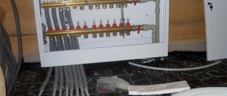
- Next, you should fix the device on the wall so that the manifold cabinet assembly for a heated floor with a liquid pump can easily fit in it, and all adjustments can be made quickly and conveniently. Usually this is a box no larger than 1x1 m in size and 12 cm thick.
- After fastening, all pipes are connected and the cabinet is assembled.
Tips and tricks
Before buying a collector, make calculations of the required length of pipes and their position. It would be better to install two 6 flow meters instead of one for 12, which will help equalize the pressure and temperature in areas that are too distant. The installation diagram of the collector must provide for its location at a level higher than the warm floor or heating circuit so that air is removed from the pipes correctly and automatically.
| Manufacturer | Cost depending on the number of flow meters, rubles | ||||
| 2 | 3 | 4 | 5 | 6 | |
| Oventrop | 4 100 | 5 150 | 6 100 | 7 000 | 8 100 |
| Watts | 3 550 | 4 650 | 5 700 | 6 750 | 7 800 |
| Kermi | 3 500 | 4 400 | 5 500 | 6 450 | 7 500 |
| Rehau | 8 200 | 9 350 | 10 700 | 12 150 | 13 550 |
| Valtec | — | 6 600 | 7 950 | 9 300 | 10 700 |
| Manufacturer | Price | |||||
| 7 | 8 | 9 | 10 | 11 | 12 | |
| Oventrop | 9 250 | 10 200 | 11 300 | 12 250 | 13 400 | 14 400 |
| Watts | 9 000 | 9 950 | 11 000 | 12 050 | 13 100 | 14 250 |
| Kermi | 8 550 | 9 600 | 10 700 | 11 750 | 12 700 | 13 850 |
| Rehau | 15 250 | 16 900 | 18 350 | 19 800 | 21 450 | 22 550 |
| Valtec | 12 400 | 13 850 | 15 250 | 17 200 | 18 050 | 19 450 |
Based on the data given in the table, we can conclude: the cost of the Kermi collector for a heated floor system today is one of the most affordable, despite the fact that it is a high-quality product from a German company, made of stainless steel.
The expensive price category is represented by the young Russian-Italian company Valtec and the German “dinosaur” Rehau. The first, which appeared in 2002, has already managed to enrich its range with brass and steel appliances and manifold cabinets. The second, having the same assortment, has more than 60 years of experience. That is why Rehau collectors for underfloor heating systems with flow meters occupy the highest price category in the table, because by trusting professionals, the chances of failure are minimal.
Types of collectors
Collectors are divided into several types depending on their price, set of functions and material of manufacture. The most expensive and reliable components are those made of stainless steel. Brass manifolds are included in the middle category; they can last a long time if they are made of a high-quality and durable alloy. Inexpensive devices are made of polypropylene and are only suitable for low temperatures. The device itself is externally a part of a pipe with the required number of bends; it can have a simple or complex configuration.
Brass
Polypropylene
Stainless steel
The list of common options includes collectors:
- with fittings for connecting circuits;
- with integrated taps;
- with valves for water regulation.
There are budget options - assemblies of double distributors: return and supply. Such devices may contain additional parts, such as a flow meter, mounting holes or taps.
Functionality and principle of operation of the flow meter
The main function of flow meters or, as they are also called, float rotameters in a heated floor system is to regulate the coolant flow in water circuits. Installing such a device allows you to:
- avoid excessive consumption of electrical energy in the process of heating the coolant;
- ensure uniform heating of all water circuits;
- eliminate temperature fluctuations in different rooms.
The need to use flow meters arises in buildings where floor coverings of different areas are heated. Large rooms require a longer pipeline length, so they heat up less intensely than small rooms. Therefore, it is possible to achieve uniform heating and ensure a comfortable temperature throughout the entire house only with such a device.
The flow meter for a floor heating system is a mechanical type device with a plastic or brass housing. Inside it is a float made of polypropylene. On the top of the body there is a transparent bulb with markings. During the circulation of the coolant, the float comes into action, moving up and down. According to its location, you can use a scale to determine the volume of liquid in the pipeline.
How to make a choice
When choosing, first pay attention to the number of circuits required for connection. When purchasing a collector device for water flooring, it is better to purchase a comb with an additional supply for one outlet. It will be needed if there is a need to split a long circuit into two branches or connect additional equipment.
You also need to decide on the type of material. The most reliable devices are made of stainless steel, natural bronze or brass. The best option would be mixing units from well-known manufacturers: Valtec, Stout or Tim.
Valtec
Tim
Stout
Exploitation
The layout of a heated floor collector is relatively simple. But during its operation, it is necessary to periodically check the performance of individual elements and the entire system as a whole. To do this, it is recommended to draw up a schedule for checking equipment and carrying out preventive maintenance of the following nature:
- Monitoring the performance of device elements.
- Checking the parameters of the coolant in each of the lines - speed, temperature. To do this, it is necessary to periodically take readings from control devices.
- Monitoring the integrity of the connection of pipelines to the combs, the absence of leaks and depressurization.
- Maintaining the temperature conditions of the system by taking data from thermometers.
By carrying out these simple procedures, you can maintain the uninterrupted operation of the entire system and its individual parts. But the main condition is the professional connection of the heated floor collector. The functionality of the device and its performance depend on the correctness of this installation stage.
Self-assembly of the device
The mounting diagram is most often already present in the kit of any collector device. You can assemble a manifold for a heated floor yourself if you follow the step-by-step instructions. The device is mounted horizontally on the wall or in a pre-prepared niche, leaving free access to the main arrow of the heating pipes. Next, you will need to connect the collector to the boiler so that the heat carrier is supplied from the bottom, and the return flow is from the top. Afterwards, a bypass valve with a temperature limiter is installed, followed by a distribution comb.
Pipes passing inside the floor are fixed from above, coming from the heating system - from below. After installation, the device must be configured according to the rules, check how tight all connections are by connecting the manifold group to the main pump. Using a pump, the pressure inside the system is built up, after which the water circuit must be left in this form for a day. If all indicators are preserved, the installation was carried out according to the rules, the unit can be operated.
A few words about the manufacturers
Collectors of Russian origin are made of stainless steel, and also have the maximum number of extensions - flow sensors, sockets, etc.
Europeans prefer ferrous metal. In terms of functionality, models of European origin are practically no different from Russian ones.
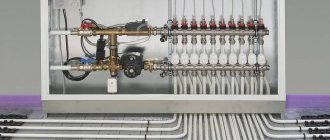
Manifold group with mixing unit and bypass for heated floors
Chinese models are devices without automation, that is, you will have to operate the collector manually. They are considered the cheapest and are excellent for servicing small residential buildings. Don't forget to install a three-way valve and pump if you plan to use Chinese products.
Which are the most famous and reliable manufacturers? Rehau products are a guarantee of quality and functionality. The name of this company is known to almost all manufacturers of heated floors, since its products undergo several stages of testing for strength, compatibility and safety.
Connecting a heated floor to a collector device
A connection diagram is first drawn up indicating the dimensions of the pipes, where they are laid and connections to the heating parts. You will need to additionally calculate the throughput of the combs and select their diameter. It is important to choose the right location for installing the collector. It is better to give preference to an area that is always freely accessible with a connection point that is located above other system elements.
Additionally, a protection system is installed, consisting of a bypass and an air valve at least at arm's length. After complete installation of the collector, you need to connect all the pipelines from the warm floor covering to it. Then they check the tightness, quality, and reliability of all joints. It is worth starting the system for the first time before installing the main coating; it is important to check the quality of heating for all lines and inspect the pipes for the level of leaks. Only after this they begin to install the finishing coating.
For the device to work efficiently, it must be correctly configured taking into account the length of the circuit and the heating load. For this purpose, the valve is placed in a given position according to the circuit number and the number of revolutions.
Seven most popular models
| Illustrations | Recommendations |
| Model No. 1: LUXOR. The Italian brand LUXOR produces reliable brass equipment.
| |
| Model No. 2: GIACOMINI. Another bright representative of Italian quality.
| |
| Model No. 3: ARS. These Turkish-Italian manifolds are of excellent quality at a reasonable price; such equipment can be called the golden mean.
| |
| Model No. 4: FADO. The company itself is Italian, but now they have begun cooperation with APC and the products can be declared as joint production.
| |
| Model No. 5: BIANCHI. The technical characteristics of the Italian collector BIANCHI are similar to its Italian counterpart from GIACOMINI. The only difference is the number of circuits and price. Here the combs come from 2 to 10 pins, and the price ranges from 9–22 thousand rubles. | |
| Model No. 6: Valtec. The Italian brand Valtec is one of the most popular on our market.
| |
| Model No. 7: Caleffi . The Italian manufacturer Caleffi operates in the luxury goods sector. The combs are made of brass, steel and polymer; the characteristics here are among the highest, but the price also reaches 43 thousand rubles. |
Is a collector necessary?
The main disadvantage of the device is its high cost, but it must be taken into account that without it, warm water-type coatings will not be able to function normally. This is only possible if the covering consists of one heating circuit. In modern heated floors, the length of pipes for installation cannot exceed 70 meters. Since this amount will only be enough for 7 square meters of area, for a medium-sized room you will need at least three circuits.
Most often, warm water-type coverings are installed in all rooms of an apartment or house. In this case, it will be necessary to install a collector to uniformly distribute the coolant supply. If we are talking about one small room, you don’t need to purchase a collector. It must be remembered that without this device the coolant will be supplied at the same temperature as in a general heating system. Also, without it it is impossible to remove air pockets and control pressure.
Settings
As a rule, a special balancing table is attached to the diagram, on the basis of which the comb can be adjusted according to two parameters: circuit length and heating load.
The table relates the circuit number and the number of revolutions from the position of the balancing valve - “closed”. Set up the comb like this:
- remove the cap from the valve that serves to protect it;
- close the valve all the way - use a hex key for this;
- determine the number of revolutions for a given circuit;
- turn off the valve to this number;
- The remaining circuits are configured in the same way.
Correct configuration and connection of the collector are necessary for long-term operation and efficient operation of the system.