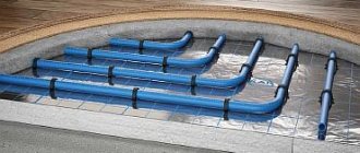
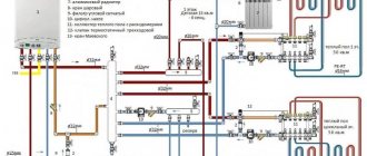
Water floor heating systems (secondary heating circuit, heated floors - TP), used together with high-temperature radiator heating (primary circuit), need to bring the coolant parameters to certain characteristics. First of all, this concerns the hydraulic and temperature coupling of both types of circuits. After all, it is important to ensure both a complete supply of coolant in the required volumes of TP communications, and to prevent overheating of the secondary low-temperature system. These tasks are assigned to the underfloor heating pumping and mixing unit (FSU). They are solved through the balanced automatic operation of shut-off and control valves and a pump unit, which ensures a dosed addition of coolant from the return line.
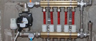
Picture 1
Setting up the COMBIMIX mixing unit for water heated floors
In order to properly configure the node, you need to know its basic functions. The unit is designed to maintain a given temperature and flow rate in the secondary circulation circuit, hydraulically linking the primary and secondary circuits. Therefore, the unit, first of all, is adjusted to the required ratio of the coolant of the primary and secondary circuits (to obtain the required coolant temperature), and is balanced with other heating devices.
The unit has only three regulatory bodies:
| 1. Secondary circuit balancing valve (2) |
Using this valve, the ratio of the coolant flow rates of the primary and secondary circuits is set, that is, the temperature of the coolant in the supply pipeline of the secondary circuit is set. The valve is turned with a hex key; to prevent accidental rotation during operation, the valve is secured with a clamping screw. The valve has a scale with valve capacity values from 0 to 5 m 3 hour.
The balancing shut-off valve is designed to link the COMBIMIX unit with other heating devices (balancing).
The valve is closed with a hexagonal cap; the valve is turned with a hexagonal key. The valve position can also be fixed with a clamping screw.
Designed to protect the pump from a mode in which there is no fluid flow through the pump. The valve is triggered by a certain pressure difference, which is set by turning the knob.
There is a convenient scale on the side of the valve with a range of values from 0.2-0.6 bar.
Algorithm for setting up the control unit:
1. Remove thermal head (1) or servo drive
To ensure that the control valve drive does not affect the unit during adjustment, it should be removed.
2. Set the bypass valve to the maximum position (0.6 bar)
If the bypass valve is triggered while the unit is being configured, the setup will be incorrect. Therefore, it should be set to a position in which it will not work
3. Calculate the position of the secondary circuit balancing valve (2).
The required capacity of the balancing valve can be calculated independently using a simple formula
t1 – Coolant temperature on the supply pipeline of the primary circuit t21 – Coolant temperature on the supply pipeline of the secondary circuit t22 – Coolant temperature on the return pipeline (the same for both circuits) Kvt – Coefficient, for COMBIMIX it is assumed to be 0.9 The resulting Kv value is set on the valve.
Calculation example Initial data Design temperature of the supply coolant - 95°C Design parameters of the heated floor circuit 45°C-35°C
The resulting Kv value is set on the valve.
To do this, you need to calculate the water flow in the secondary circuit; kg/hour and pressure loss in the circuits after the unit; m.v.st according to formulas.
Where Q is the sum of the thermal power of all devices connected after COMBIMIX. с – heat capacity of the coolant; if the coolant is water, then c = 4.2 kJ / (kg•°C) If another coolant is used, then the heat capacity should be taken from the technical passport of this coolant. t21; t22 – Temperature of the coolant in the supply and return pipelines of the circuit after the COMBIMIX unit. Pс – Pressure loss in the design circuit of the heated floor (including collectors). This value can be obtained by performing a hydraulic calculation of the heated floor. To do this, you can use the free program Valtec.prg
Using the pump nomograms presented below, we determine the pump speed. To determine the pump speed, a point is marked on the characteristic with the corresponding pressure and flow rate. Next, the nearest curve is determined, above this point, it will correspond to the required speed.
For COMBI 01/04 and COMBI 02/4 For COMBI 01/06 and COMBI 02/6
Example for a heated floor with a total power of 10 kW and with a pressure loss in the most loaded loop of 40 kPa (4.07 m.w.st.) Water flow in the secondary circuit:
Pressure loss in the circuits after the CombiMIX unit with a margin of 1 m. in st.
Pump speed selected – MAX at point (0.86 m3/hour; 4.05 m.w.st.)
If it is not possible to calculate the pump, then you can skip this step and proceed directly to the next one. At the same time, set the pump to the minimum position. If during the balancing process it turns out that the pump pressure is not enough, then switch the pump to a higher speed.
5. Balancing the branches of the heated floor
Close the balancing shut-off valve of the primary circuit. To do this, open the valve cover and use a hex wrench to turn the valve counterclockwise until it stops.
The branches are balanced with each other using balancing valves or flow regulators (not included in the COMBIMIX kit). If there is only one circuit after COMBIMIX, then nothing needs to be linked.
The balancing process is as follows: Balancing valves/flow regulators on all branches of the heated floor are opened to the maximum, then a branch is selected in which the deviation of the actual flow rate from the design one is maximum. The valve on this branch closes to the required flow rate. Thus, it is necessary to adjust all the branches of the heated floor. If after balancing all the branches the flow rate is off, then the flow rate in the branches should be adjusted.
To indicate flow, you can use the VT.FLC15.0.0 flow meter. If it is not possible to use a flow indicator, then you can balance the branches approximately by heating the floors or by the temperature of the return coolant.
If during the balancing process it was not possible to obtain the required flow rate through the branches even with the valves open, then the pump should be switched to a higher speed.
6. Linking the COMBIMIX unit with other heating devices.
We open the balancing shut-off valve of the primary circuit using a hex key until the required coolant flow through the primary circuit is ensured. The linking of the node is carried out together with the linking of the rest of the system.
You can control the coolant flow using flow meters or by monitoring the temperature of the coolant in the return pipe of the heated floor. The coolant flow in the primary circuit can be calculated using the formula:
Q – Sum of thermal power of all devices connected after COMBIMIX. с – heat capacity of the coolant; if the coolant is water, then c = 4.2 kJ (kg•°C) If another coolant is used, then the heat capacity should be taken from the technical passport of this coolant. t1;t21 – Temperature of the coolant in the supply and return pipelines of the primary circuit (the temperatures of the coolant in the return pipeline of the primary and secondary pipelines are the same).
Example: for a heated floor with a total power of 10 kW The design temperature of the supply coolant is 95°C The design parameters of the heated floor circuit are 45°C-35°C
7. Setting the bypass valve
The valve pressure value is set to 5-10% less than the maximum pump pressure at the selected speed. The maximum pump pressure is determined by the pump characteristics.
The bypass valve should open when the pump approaches a critical point, when there is no water flow and the pump works only to build up pressure. The pressure in this mode can be determined from the characteristic.
An example of determining the setting value of a bypass valve.
In this example, it can be seen that the pump, in the absence of water movement at first speed, has a pressure of 3.05 m.v.st (0.3 bar); at medium speed - 4.5 m.v.st (0.44 bar); and at a maximum of 5.5 m.w.st. (0.54 bar). Since the pump is set to maximum speed, we select the setting on the bypass valve 0.54-5% = 0.51 bar
8. Checking the correct operation of the unit
You must ensure that the COMBIMIX node is working correctly. The check is carried out based on the uniform heating of all branches of the heated floor and the correct temperature ratio of the coolant in the supply and return pipelines. This check can be performed even if the current coolant parameters do not correspond to the design ones. The node is configured correctly if the following condition is true:
Where temperatures with the index “p” are calculated values, and temperatures with the index “f” are actual values.
If the condition is not met, then open or close the balancing shut-off valve a quarter turn and take readings again.
If the condition is met, then you should reinstall the thermal head, put on all the protective caps and tighten the balancing valve clamping screw. The unit is ready for use.
Example: Design temperature of the supply coolant - 95°C Design parameters of the heated floor circuit 45°C-35°C Actual readings taken from thermometers Supply coolant temperature - 95°C Coolant temperature at the supply to the secondary circuit 32°C Coolant temperature at the return pipeline secondary circuit 25°C
(deviation 6.6% is less than 10%, therefore the system is configured correctly)
Source
Heating manifold, question about correct assembly?
Dear professionals! Please tell me. The manifold is assembled, there is a three-way Esbe valve for the heated floor. He is supposed to mix the return water from the floors, but in fact he doesn’t mix it. The pump (3) draws return flow from the manifold. What to do?
- View profile
- Private message
KDL, it is worth installing a check valve on the return line of the floor pump group. And the scale on the mixer was placed incorrectly. The arrow on the mixer handle indicates the position of the damper. That is, the scale should be placed in the lower left quadrant, between the bypass and feed. The sign should be located in the same sector.
- View profile
- Private message
How is that? Maybe a pitch?
- View profile
- Private message
How is that? Maybe a pitch?
BV, the operation of the remaining pumps increases the pressure in the return manifold and reduces it in the supply. This is why the carrier in the by-pass flows along with the floor carrier from the return manifold to the supply manifold. Known issue. Treated with a separate boiler pump and arrow
- View profile
- Private message
cineman wrote: Treated with a separate boiler pump
Yes, I didn’t even think that it might even occur to me to install collectors if the boiler does not have a pump
Although all the other pumps could be running at maximum, even the boiler pump couldn’t cope.
At all. spy on the author’s system through the “keyhole” of his scanty messages and guess. Is it necessary?
- View profile
- Private message
Good afternoon Thanks for your comments! From the above, did you highlight the following questions?:
- Is it necessary to install a pump from the boiler to the collector?
- Is it necessary to move the check valve below the mixer? p.s. Pumps run at minimum. I'll rearrange the scale and handle of the mixer!
- View profile
- Private message
KDL wrote: is it necessary to install a pump from the boiler to the manifold.
Depends on the resistance of the route from the boiler to the collector and on the design of the boiler itself. The boiler may be wall-mounted, with high heat exchanger resistance. Some floor-standing boilers require the installation of a boiler circulation pump. This is extracted from the instructions for the boiler. The pump activation circuit may be different. This may be an arrow in front of the collector, or it may be a by-pass that closes the collectors at the end of the collector opposite to the connection point. A separate issue is connecting the boiler to the boiler. Its return may be too cold at the beginning of the heating phase, which is dangerous for the cast iron body of the boiler. If the flow rate of the boiler pump is higher than the flow rate of the boiler pump, in any scheme, an admixture of the supply to the boiler return will be formed, which protects the cast iron body from temperature shock. Modern thought is moving towards synchronizing the flow rates of the boiler pump with all collector pumps, but a sustainable solution is not yet in sight. There are no check valves on your manifold at all. And they should be installed on the supply side in each pump group after the pump. When the heating pumps are turned off during the boiler heating phase, the medium can continue to circulate under the influence of a gravitational difference. Or, on the contrary, the direction of circulation of the carrier may change due to the vacuum in the supply manifold created by the boiler pump. In any case, a check valve after the pump is a standard solution. In some pump groups they are not visible, because they are combined with shut-off valves at the outlet of the group. I try to use special Oventrop check valves combined with the pump flange. They are expensive, but do not stick together like cheap valves. They also have a screwdriver slot on the outside for forced opening, which is useful when starting and draining the system.
KDL wrote: is it necessary to move the check valve below the mixer?
The valve is needed on the mixer return, between the manifold and the bypass. But the need for it arises precisely because of the lack of a boiler pump, which raises the pressure in the supply manifold above the return manifold. But it’s worth putting a valve after the sex pump. Without it, you can get a warm floor with the pump turned off in the summer. This happens with floors and radiators located above the boiler.
The sex pump rarely works at minimum. Its task is to reduce the delta with high flow.
How to set up the bypass of the TIM JH-1036 mixing unit
The TIM JH-1036 pumping and mixing group has an adjustable bypass. There is a scale with a gradation from 0 to 5, but it is no longer possible to find out what these numbers mean after installing the bypass. It is difficult to understand why it is needed, because other mixing units for heated floors do not have such a device.
I had to study in great detail the operation of the bypass of the mixing unit as a result of incorrect connection of its input and output to the heating system.
After the previous installation of the TIM JH-1036 mixing unit, it was not possible to configure the bypass, since there are no instructions for setting it up, and I did not study the design before installation - do not remove it. Now, before installation, I studied and took photographs of the internal structure of the mixing unit.
What regulates the bypass of the TIM JH-1036 mixing unit.
The mixing unit has a conditional mixing chamber through which the underfloor heating circuit and the boiler heating circuit pass.
Typically, a heated floor mixing unit has one adjustment parameter - the water temperature in the heated floor circuit. The TIM JH-1036 mixing unit also has some kind of bypass, and even adjustable. And this is not the bypass balancing bypass, which is triggered by excessive pressure developed by the pump.
The pressure balancing bypass can be seen in the photo - the rightmost personal belongings.
I need it because it is possible to block all heating directions of the heated floor as a result of automatic regulation. By the way, I still haven’t figured out how to regulate the balancing bypass TIM M307-4 - maybe someone can tell me.
As for the mixing chamber bypass, you can find the following graphic explanation of the operation of the mixing unit bypass:
Little is clear from these diagrams.
Moreover, it is not clear what the numbers on the scale mean and what the current value is tied to. All this can be found out only by holding the TIM JH-1036 mixing unit in your hands:
It turns out that the adjusting screw turns the cylinder, which has a slot that closes when turned. Through this slot, water can be pumped by a circulation pump, bypassing the conditional mixing chamber.
It should be taken into account that the sticker with a scale from 0 to 5 can be pasted arbitrarily.
The maximum opening of the slot (pictured above) corresponds to setting the adjusting screw to position 5 (pictured below).
The technological ledge on the mixing chamber body can be taken as a conventional point for reading the scale value. When the scale value is 0, the gap is maximally closed. In this position, all the water pumped by the circulation pump along the contours of the heated floor passes through the mixing chamber.
With the bypass completely closed, the thermal power of energy taken by the mixing unit from the heating system is maximum.
If the bypass is completely open, then part of the water circulates through the heating circuits without entering the mixing chamber - and the thermal power of extraction is minimal.
But in practice it turned out that not only thermal power is regulated by the bypass.
Installation. Where is it installed?
Installation is carried out in the return branch circuit, which ensures a permanent supply of liquid to the batteries when operating one circuit for hot water supply and space heating. When installing balancing valves on each battery, installation is carried out in the lower part on the outlet pipe diagonally from the spherical coolant supply valve, which is mounted on top.
In a private cottage, differential pressure regulators are used for each battery, and for each outlet pipe they are provided with union nuts or another type of threaded connection. Automated installations do not require configuration. When using a two-valve design, the passage of the thermal energy source to the batteries furthest from the boiler is automatically increased.
Balancing is achieved by increasing the pressure on the circuits leading to the batteries closest to the boiler. The need to accurately calculate the indicators that are set on the valve is due to the features of the model. Manual valves typically require adjustment using calculations or measuring equipment.
In high-rise multi-storey buildings, valves are mounted on each common vertical pipeline (in the return line). When carrying out calculations, the given quantities of heat energy source supplied by an electric pump and the number of risers are used.
Experimental determination of the value set by the bypass.
Before installing the bypass, it would not hurt to make sure what value corresponds to the full opening and closing of the bypass.
Just be careful - the edges of the crack are sharp, like blades.
If the mixing unit is already installed, but the sticker with the 0-5 scale is affixed differently, you can carry out an experiment.
By turning the adjusting screw with a 10mm wrench, find out what position of the scale is the maximum and minimum water flow rate on the flow meters of the underfloor heating manifold.
If there is no collector or flow meters, which is very in vain, you can find the maximum and minimum temperatures at a limited temperature of the coolant in the main system (at the inlet to the mixing unit) and the maximum possible setting of the thermostatic head of the mixer.
The temperature of the coolant on the boiler is limited so that the mixer cannot cope with the set temperature.
Balancing valve device
Valves consist of several key elements:
- a body with pipes for connecting pipes and an internal round channel with an expansion at the top (seat);
- adjustment handle;
- fittings for flow measurements;
- spindle with a cone (the cone lowers into the seat when screwing and limits the passage of the thermal energy source).
The type, configuration and functionality of the balancing valve may vary depending on the selected model. Some models are equipped with a drain pipe or flow meter.
Most modern models are equipped with a pair of measuring fittings that allow you to measure the volume of supply of a liquid source of thermal energy at the input and output. Also, some models are upgraded with a spherical locking mechanism, which allows you to completely limit the flow of coolant or drain the waste liquid.
Automated valves have a servo drive instead of a rotating head. This element pushes the locking mechanism, and the degree of overlap is determined by the amount of voltage applied.
How the bypass of the TIM JH-1036 mixing unit works.
It would seem: we set the thermal power of the mixing unit to maximum, completely closing the bypass slot - and that’s it.
But the flow meters of the underfloor heating collector make it possible to find out that not only the thermal power is regulated by the bypass. When the bypass is completely closed, the floats of the flow meters float up sharply.
It turns out that the water flow through the heating circuit with a completely open bypass is more than twice as much as with a completely closed one.
This is not surprising - pumping water through the mixing chamber requires pump power, which affects the speed of water flow.
At maximum thermal power of the mixing unit, the flow rate of water along the contours of the heated floor is minimal. To uniformly heat the entire underfloor heating circuit, it may be necessary to turn on the pump at second speed, which will increase the noise of the heating system.
It turned out that in my system the minimum thermal power of the mixing unit is sufficient to ensure a coolant temperature of 32 degrees at the supply manifold with all directions of underfloor heating open, even when starting a cold heated floor.
But in other cases it may be necessary to increase the selection power.
How does installing a bypass mixing unit TIM JH-1036 affect the heating system.
It was necessary to carefully study the operation of the mixing unit as a result of incorrect connection of the mixing unit to the heating system.
Different positions of the bypass adjustment led to the fact that different pipes connecting the mixing unit to the heating circuit were warm.
That is, the supply and return of the mixing unit swapped places when the bypass adjustment position changed. Mystic.
So I found out that I made the connection incorrectly, having mixed up the supply and return to the mixing unit .
Theoretically, the circulation pump of the heating floor mixing unit should not have influenced the heating boiler circuit in any way - the mixing unit pump releases water at the same point from which it takes it. The circulation pump of the mixing unit pumps water along the contours of the heated floor, and the boiler circulation pump pumps water through the mixing chamber of the mixing unit.
But involuntary experiments made it possible to find out that even the minimum power of the mixing unit pump with a closed bypass is enough to carry out additional circulation in the main heating circuit.
This is possible if we assume that the equivalent circuit (by analogy with problems in electrical engineering) of a heating system with a TIM JH-1036 mixing unit is as follows:
Where “R1” and “R2” are resistances in the mixing chamber, regulated by the bypass.
“Boiler circuit” is an old heating system with radiators and a boiler.
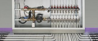
It’s not for nothing that the mixing unit clearly indicates which pipe should be the supply pipe. The photo shows a correctly connected mixing unit.
Then I decided that it wouldn’t hurt to familiarize myself with the theoretical foundations of the operation of water-heated floors, and as a result I created a page with links to the theory.
Two pumping and mixing units for underfloor heating in one heating system.
I ended up with two underfloor heating mixers in one heating system.
I made one right away at the first stage of repair and installed it temporarily.
So far, this mixer has controlled one branch of the heated floor. Then he intended to move it after the renovation was completed in other rooms. I laid pipes in the floor to connect this branch to the mixer in a new location.
But nothing is more permanent than temporary.
And in a new location he installed another similar mixer.
Someday I will remove the first mixing unit - the manifold of the second mixing unit has fittings for connecting this branch and the pipes have already been laid.
Please note that the mixer in the first photo is not capable of providing a coolant supply temperature of more than 25 degrees when the temperature set on the boiler is 50 degrees.
The photo shows a coolant temperature of 30 degrees, achieved when the boiler temperature is 60 degrees and the thermostatic mixer head is set to 40 degrees.
This is understandable with such a connection.
The paradox is that this (25 degrees) is enough to relatively quickly heat the room by a couple of degrees, maintaining the set temperature.
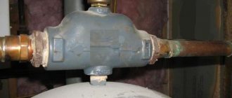
Why is a check valve needed?
During operation, hydraulic pressure appears inside the heating system, which may be different in different areas. The reasons for this phenomenon are very different.
Most often, this is uneven cooling of the coolant, errors in the design and assembly of the system, or its breakthrough. The result is always the same: the direction of the main fluid flow changes and it turns in the opposite direction.
This is fraught with very serious consequences, including the failure of the boiler, or even the entire system, which will require significant repair costs in the future.
For this reason, experts strongly recommend installing a check valve. The device is capable of passing liquid in only one direction. When reverse flow occurs, the locking mechanism is activated and the hole becomes impassable for the coolant.
Thus, the device is able to control the flow of liquid, passing it in only one direction.
The principle of operation of the check valve is very simple. It passes the coolant fluid in a given direction and blocks the path when it tries to move in the opposite direction
For normal operation of the system, it is necessary that the device does not create additional pressure and freely passes the coolant moving to the radiators. Therefore, it is extremely important to choose the right product.
Select the bypass adjustment value 0-5 depending on the situation.
Using the example of these two mixers, we can now show the difference between the different bypass adjustments of the TIM JH-1036 mixing unit.
Bypass setting value is 0.
The first mixer operates in conditions where the bottleneck of the system is the heat supply from the system.
It is connected like a radiator in a one-pipe system.
Just in case, I made a thickening at the connection section from 25 to 32 diameters and installed a tap, since I doubted that a sufficient amount of water would flow in and provide sufficient power.
This local heating subsystem is built, of course, on one mixing unit without a collector group.
There should be no problems with circulation along one circuit.
Therefore, we set the value of the bypass adjustment bolt to 0.
We make the circulation through the heated floor circuit minimal, and the circulation through the mixing chamber maximum.
It was shown above that here the mixer pump will help the circulation through the heating system a little more.
How is the price determined?
This is due to the fact that the price for a specific plot will be much lower. This is due to the mechanism for setting the price for a specific plot.
So, if there is a paid acquisition of land, its cost will be determined based on a similar cadastral value. At the same time, you need to know that in each specific case the calculation of the value will be carried out based on the purpose for which the land is being purchased.
So, for example, if it is used for individual housing construction, its value can range from 3 to 100% of the same cadastral value (in the event that a house on such a plot has not yet been built).
In the event that we are talking about the use of a land plot for organizing agricultural production (if it is impossible to develop the plot free of charge), then the price here cannot be more than 3% of the cadastral value of a specific plot.
In the case of purchasing a plot at auction, the value will be calculated from the cadastral to the average market value for a specific type of plot.