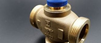
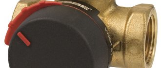
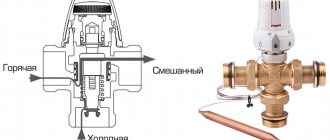
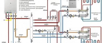
The uninterrupted operation of any heating device depends on the correct selection of components, and water heated floors are no exception. In this design, an important point is given to maintaining the temperature level and intensity of coolant supply - this function is assigned to shut-off valves: a two-way or three-way valve.
In our article we will tell you what a three-way valve is, the principle of its operation, and what types there are. You will also learn which valve to choose for a heated floor, as well as how to install it yourself.
Application area
Underfloor heating systems are increasingly popular in residential buildings today, but without a control valve it is impossible to ensure proper heating. A three-way tap is an element designed to adjust the heating level in a water floor that is filled with screed.
The valve is installed both as a complete set with a mixing and distribution unit, and as an independent device. In small rooms (bathtub, toilet, kitchen), there is no point in installing a multifunctional collector - it is expensive and not justified.
A three-way thermomixing valve can control the temperature and regulate the volume of liquid for such rooms.
Main areas of use:
- In a radiator heating system.
- In the DHW system.
- In warm floors.
Design
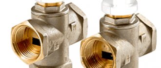
A three-way mixing valve has a control element, which is a rod or ball. The rod moves vertically, the ball moves around its axis. Since the movement of the control element does not completely block the flow of the working fluid, it is mixed and redistributed. The simplest models are a regular faucet. Their main advantage is low cost and design simplicity. The disadvantage is the impossibility of stabilizing the outlet temperature. Despite the disadvantages, the faucet can be installed in underfloor heating systems. Now let's imagine a faucet with an electric drive. This design is already more functional, since it is able to regulate the temperature automatically. A simple valve is a balancing valve. Its main function is to adjust the cross section for the passage of the work flow. Conventionally, the principle of its operation can be described as follows:
- The handle is turned 50% - uniform mixing of the two flows, since the inlet valves will be equal.
- The handle is turned 100% - the first valve is fully pressed and blocks the movement of liquid flow.
Modifications on the market may have different handle rotations, but the principle of their operation remains the same. The tap and its position are manually adjusted, thereby ensuring a balance between the two flows.
Functions
Water heated floors have significant differences from standard radiator heating. The floor pipeline, which lies in a cement screed, requires water at a certain temperature level, much lower than that circulating in the radiators. Therefore, it is necessary to install a three-mix running unit, in which the coolant will be brought to the required degree.
Bringing the liquid to the required degree of heating that meets the standards for underfloor heating (which ranges from +35 to 55 degrees) is the main function of a three-way thermomixing valve.
Main varieties
Three-way valves come in three types:
- Hydraulic.
- Electrically driven.
- Pneumatic.
Electrically driven devices (for example, the ESBE model) differ slightly in their operating principle. The electrical appendage acts here like a regular thermostat: thanks to it, the flows are not only mixed, but also maintained at the desired temperature. During a decrease or increase in temperature, the position of the shut-off valves is automatically changed. As a result, the flow cross-section increases or decreases. At the same time, the cross-section at the inlet of the cold flow changes, which makes it possible to impart a stable temperature to the outlet water. In this case, the three-way valve is completely dispensed with without human control: the control of the equipment falls on automation.
The ESBE valve with electric drive and thermostat can be successfully used in heating systems and hot water supply. Strictly speaking, such a valve can be equipped with any type of pipeline where it is necessary to mix two liquid streams and maintain a stable temperature. Even the highest quality and reliable models of a three-way valve with a thermostat have one common drawback for products of this type: the inlet points through which liquid flows are greatly narrowed. As a consequence, this provokes an increase in hydraulic resistance.
These types of taps are great for water pipes. ESBE valves are often equipped with heated floors, although a special connection diagram is used. Along with the modifications mentioned above, three-way thermostatic valves can be found on sale. Despite the apparent similarity of these devices, their functions differ in many ways. Thermostatic varieties use thermostats with a remote-type sensor. In addition, the operating principle here is also different.
Unlike standard models, thermostatic valves control flow at only one point. The other two inlets are in a permanently open position, with a stable cross-section
When purchasing such a design, it is important to test the second point for narrowness, otherwise difficulties in the operation of the device may arise due to high hydraulic resistance. If such a defect is detected, the problem can be solved by installing a mixing valve in an additional circuit
Design and principle of operation
A mixing valve is a device for mixing and regulating water flows; it has three openings: two inlet and one outlet. In the space between the inlet holes there is a heat-sensitive damper; it is responsible for regulating the movement of liquid - cooled and heated. Modern devices are equipped with a thermal head or control valve.
The heating floor valve operates continuously. The step-by-step process is as follows:
- heated water is supplied to the first inlet - its temperature is determined in the valve;
- if the heating degree of the water exceeds that required for heated floors, then the supply of cooled liquid from the return line opens through the second hole;
- inside the valve, heated liquid is mixed with cooled liquid;
- after obtaining the desired temperature, the return flow is closed;
- The coolant is supplied through the outlet to the underfloor heating pipes.
For the thermal valve to work effectively, it is necessary to maintain constant pressure in the line.
When operating an automatic thermo-mixing tap equipped with a servo drive, heating is carried out in 3 minutes ; if there is a thermal head, the liquid is heated in 15 minutes .
Valves classification
Without lengthy introductions, we note that the device can be of two types according to the principle of operation. It could be:
- dividing;
- mixing.
The features of each type of action are clear from their names. The mixing device consists of two outputs and an input. In other words, it is necessary to mix fluid flows, which may be required in order to reduce its temperature. By the way, this is the most optimal option for setting the desired mode in the “warm floor”.
The procedure for adjusting the temperature regime is extremely simple. You just need to know about the current temperature indicators of the incoming liquid flows, accurately calculate the required proportions of each of them so as to obtain the required indicators at the output. By the way, this device, subject to proper installation and adjustment, can also function for flow separation.
But the separating valve divides one flow in two, therefore, it is equipped with one inlet and two outlets. This device is used primarily to separate the flow of hot water in hot water systems. Although quite often it is found in the piping of air heaters.
Externally, both options are almost identical. But if you look at their cross-sectional drawing, their main difference is immediately visible. The rod, which is installed in a mixing-type device, has one ball valve. It is located in the center and blocks the main passage.
As for separating devices, the stem has two such valves, which are installed at the outlets. They function according to the following principle: one of them is pressed against the saddle, closing the passage, and the other, in parallel, opens passage No. 2.
According to the control method, modern models can be:
- electrical;
- manual.
In most cases, a manual device is used, which in appearance resembles an ordinary ball valve, but is equipped with three outlet pipes. But electric models with automatic control are used mainly in private homes, namely to distribute heat. For example, the user can set the temperature regime by room, and the working fluid will flow in accordance with the distance of the room from the heating device. As an option, you can combine it with a “warm floor”.
Video - Device in a boiler group
Three-way valves, as well as other devices, are determined in accordance with the pressure in the system and the diameter of the inlet. All this is regulated by GOST. And if the requirements of the latter are not met, this will be regarded as a gross violation, especially when it comes to the pressure indicator in the line.
Brass Fittings and HDPE Piping
We advise you to read our guide to the selection and installation of brass fittings for HDPE pipes, all
Kinds
Esbe three-way for heated floors, why is it needed.
Three-way thermal valves come in separate and mixing types. For underfloor heating, mixing valves are used.
In addition, they have different implementation methods; they can be manual or automatic. They also differ in their design - the location of the holes (inlet and outlet).
Manual
The price of a manual device is not high, but it is rarely used because it is not convenient. Suitable only for small rooms - bath, kitchen. The temperature level and volume of supplied coolant are adjusted manually using a handle.
Automatic
Automatic valves have a thermal head or an electric drive, which can be controlled by a sensor.
Types of mixing units:
- Simple - if the temperature rises, the liquid expands, the damper opens, cold and hot water mix.
- Three-way valves with a thermal head with a remote thermostat for heated floors are more advanced models. They are widely used because they are accurate and do not require electricity to operate. Average price from 500 rubles to 2500 rubles.
- Three-way valves for heating with a thermostat - they regulate the flow of heated and cooled water, and also control the temperature with a built-in thermostat. The expansion and contraction of the holes occurs automatically, depending on the temperature of the liquid.
- With an electric drive (drive with a magnet or servo drive) - the damper in the valve is activated under the influence of an electric motor, it is controlled by a controller, and a signal is received from a temperature sensor. They are easy to connect, so they are widely used. But unreliability is their main drawback, since they depend on electricity. Their cost is higher than with a thermal head, approximately 4 - 5 thousand rubles.
- With pneumatic or hydraulic drive - used more often in production, for devices with high pressure. They have a high cost, but their service life is longer.
- Electronic - adjustment is carried out by a built-in electric motor or a control element with a thermometer.
Mixing unit
The use of the esbe valve for heated floors has its own specifics. The location of the mixing unit is an additional circuit. Switching with the manifold-distributor is carried out through two points: this allows the coolant at the inlet to constantly circulate. The inlet flow is opened only when there is a need for additional heat.
The mixing unit is connected to the valve and thermostat. Considering the narrowness of all valves at point 2, the pump may encounter problems with insufficient flow. To solve the problem, it is necessary to install a second line that reduces the level of electricity consumption. But such a need does not always arise, because The cross-section of some three-way valves is quite large.
In a situation where the first line has insufficient flow power, the thermostat does not block the passage on the required scale.
To get out of this situation, two options are usually used:
- The second line will narrow.
- A balancing valve is installed.
The second method is considered more effective, because In this case, the flow is adjusted more accurately. There is another scheme for connecting an esbe three-way valve for a heated floor - connecting the pump to the second line: here a balancing valve is not needed. This allows you to equalize the temperature in the inlet and outlet flows.
Installation of a faucet with a thermostat can be carried out in single-circuit systems. Their simplest variation is a warm floor of a small area. In this case, using a large mixing unit is not very practical. A more expedient solution would be to connect a single-circuit heated floor. The installation of a three-way valve with a thermostat is carried out on the return pipe containing the cooled coolant. Thanks to the thermostat, shut-off valves are activated, which increases the cross-section. When the pipe heats up, the temperature sensor detects this and reduces the flow.
Manufacturing materials
Three-way thermomixing valves are made from the following materials:
- Brass is a copper alloy with zinc additives. The product is not subject to corrosive destruction, it is strong and durable. Sometimes these thermomixers have a chrome or nickel coating, which protects against darkening. This option is most often used in residential areas.
- Bronze is a copper alloy with tin additives. It is rare, although the quality is no worse than brass.
- Stainless steel is an excellent metal for making control products. It is characterized by durability, strength, and corrosion resistance. But the cost of appliances made from it is high, so they are not suitable for a private home.
There are titanium and carbon steel regulators, but they are recommended for industrial use. Valves are produced from silumin (an alloy of aluminum and silicon), their disadvantage is low strength.
How does the water mixing system work?
Mixing system for several rooms
Relatively speaking, the mixing unit for a heated floor works like this:
The hot liquid reaches the underfloor heating manifold and is stopped using a safety valve if its temperature is too high. The pressure triggers the damper and begins to supply cooled liquid from the return (which has already passed through the circuit and cooled down). As soon as the temperature becomes optimal, the valve closes back. There are several ways to organize water mixing, which we will discuss below.
Also, often the collector unit not only maintains the optimal temperature level, but also increases the pressure in the circuit to improve circulation.
It usually consists of the following elements:
- The safety valve we described above. It turns on mixing if the temperature gets too hot.
- A circulation pump that increases water pressure and makes heating even.
In addition, the unit may also include a bypass - to protect against overloads, valves for draining water and air vents. Depending on your requirements, its assembly can be done in several ways.
The mixing unit is always installed before the heated floor contour, but the location of its attachment can be different: directly in the room, in the boiler room or another room in the manifold cabinet.
The main difference between mixing units and each other is the valves used in them. The most popular are two- and three-way valves.
Two way valve
Two way supply valve
Also, such a valve is often called a supply valve. It has a thermal head with a liquid sensor that constantly checks the supplied water. If necessary, it cuts off the supply of hot liquid from the boiler.
As a result, water from the return line is constantly supplied for mixing, and when it cools down, a hot portion is added by a valve. Thus, the warm floor of an apartment or house does not overheat and its service life increases. This option has a small throughput, so the adjustment occurs smoothly, without sudden jumps.
Most craftsmen prefer to install this type of mixing, but to use it, the heating area should not exceed 200 square meters.
Three-way valve
This type combines the functions of a bypass valve and a bypass balancing valve. Its main difference is the mixing of hot coolant inside it with cooled return fluid. They are often equipped with servos that control thermostatic devices and weather controllers.
Inside this valve there is a damper, which is installed in the area between the supply and return pipes. By adjusting the position of the damper, the ratio of the supplied water changes.
Three way mixing valve
This type of connection is considered more universal and is well suited for large systems with a large number of circuits and the use of weather controllers.
It is also worth talking about the disadvantages of this connection scheme. It is possible that, following a signal from the thermostat, the valve will fully open and allow 95 degree water into the circuit. In a heated floor system, sudden changes in temperature and pressure are unacceptable; heated floor pipes can simply burst.
The second disadvantage is the large capacity of the three-way valve. That is, even a slight shift in temperature can change dramatically.
Outdoor temperature sensors
Connection together with an outdoor temperature sensor
Weather-dependent sensors automatically adjust the temperature to suit weather conditions. For example, during a sudden cold snap, they give a command to increase the floor temperature.
The valve rotates a maximum of 90 degrees. The controller divides them into 20 segments of 4.5 degrees each and checks the supplied temperature every 20 seconds. If the actual temperature does not correspond to the optimal temperature, the valve is turned 1 notch. In addition, some species may reduce water supply when no one is home.
Of course, this can be done manually, and tighten the valve each time, but it will be difficult to set the optimal heating mode each time.
Advantages and disadvantages
Three-way thermostatic mixing valves are simple in design, yet reliable and durable. Their use allows for high-quality and precise control of the floor heating level.
Thermostatic valve for heated floors: types and their design, how to choose, installation diagrams and alternative connection methods
The devices are sealed and compact. Plus - they do not allow the pipes and screed to overheat, which extends the life of the system.
The benefits of control valves are irrefutable, but they have a number of disadvantages:
- They increase hydraulic resistance - this negatively affects the functioning of a unit that has more than one collector.
- There is a risk of a large volume of hot coolant entering the floor pipes. And this can lead to leakage and airing of the system. Such problems most often occur when the device is starting up.
Simplified mixing elements with temperature lock
An autonomous three-way valve of a simplified type can be installed in simple heating systems of country houses, where heat is obtained from a TT boiler. To function, it does not require a thermal head with a temperature sensor, and there is no rod there.
The thermostatic element, which is installed inside the housing, is adjusted to a certain temperature of the coolant at the outlet, for example. 50 or 60 °C (must be marked on the body).
The mixing valve of this sample always maintains the set temperature of the coolant at the outlet; this setting does not change. This gives rise to positive and negative aspects when using such fittings:
- advantage - cheaper, unlike a unit with a thermal head. The difference is about 30%;
- disadvantage - there is no possibility of adjusting the heating of the exiting coolant. If the factory settings are set to 55°C, then it will constantly supply water at this temperature ±2°C;
- Before purchasing a valve of a simplified design, carefully study the documentation for the solid fuel boiler; it usually indicates the minimum return temperature.
A thermostatic three-way valve is a rather useful thing in the heating system of a private home, which makes it possible to efficiently use the heated liquid, and thereby save fuel. Moreover, this part allows you to increase the service life of solid fuel boilers, and also plays the role of a safety element. On the other hand, you should not sculpt the valve just anywhere; it is always better to consult with a specialist who is well versed in this.
Manufacturers
Preference should be given to mixing valves from manufacturers that have proven themselves well in the market. Such companies include:
- Esbe (Sweden) - occupies a leading position in the quality of products of this type. The valves are reliable, with a warranty period of more than 5 years.
- Valtec is a Russian-Italian company; its mixing taps have good characteristics at an affordable price. Warranty - 7 years.
- Honeywell (America) - the priority of mixers from this company is considered to be convenient and uncomplicated installation. They are reliable, but expensive.
However, it should be remembered that even high-quality products if installed incorrectly will not ensure correct operation of the system.
Expert advice
Before choosing control equipment, you need to decide what area needs to be heated. If you will be heating a bathroom, part of the floor of a bedroom or a children's room, there is no need to purchase fittings with a thermal head - it is easier to use a manually operated three-way valve than to install a full-fledged expensive mixing unit.
The cost of a mixing and distribution unit with shut-off and control valves, a manifold, a pressure gauge, and a Mayevsky tap exceeds the cost of all pipelines (if they are made of polymer and not expensive copper).
If the underfloor heating system includes several rooms, then it is necessary to order a project from a qualified plumbing engineer before installation - it will indicate the characteristics of the valve. If there is a large area of heated floors and a large number of rooms, one or more mixing units will be needed.
The connection diagram of each unit includes a manifold - a distribution comb, to which heating pipelines are connected. A three-way mixing valve and pump are installed in front of the manifold. The valve can be with a thermal head or with sensors, a controller and an electric drive.
How to choose?
It is recommended to select a three-way valve in specialized stores. When choosing a model, you need to take into account its characteristics. When purchasing a device you need:
- study all documentation - warranty, manufacturer’s certificate, installation and operating instructions;
- give preference to bronze or brass devices - they will not expand when heated;
- based on the valve capacity - this parameter must correspond to the boiler performance;
- select a valve with a cross-section that exactly matches the size of the floor pipes; if there is a mismatch, you will have to buy adapters.
An important point is that even the apparent coincidence of the diameters of the valve inlet and outlet does not indicate the throughput level. This is affected by the size of the internal cross-section of the holes. This parameter is specified in the accompanying documents.
You need to choose a device based on the size of the heated room - for large areas an automatic device is recommended; it is able to maintain heating at the proper level. For small rooms, a simple one with a thermal head will do the job, so there is no point in overpaying for a more complex model.
When purchasing, you must visually inspect the device for chips and cracks. If the device is brass, then the inside should be golden.
Purchasing automatic devices will facilitate the adjustment process. And the presence of software will allow you to adjust the temperature taking into account the time and day of the week.
Mixing unit
The use of the esbe valve for heated floors has its own specifics. The location of the mixing unit is an additional circuit. Switching with the manifold-distributor is carried out through two points: this allows the coolant at the inlet to constantly circulate. The inlet flow is opened only when there is a need for additional heat.
The mixing unit is connected to the valve and thermostat. You need to understand that a thermostat for a water heated floor allows you to reduce heating costs. Considering the narrowness of all valves at point 2, the pump may encounter problems with insufficient flow. To solve the problem, it is necessary to install a second line that reduces the level of electricity consumption. But such a need does not always arise, because The cross-section of some three-way valves is quite large.
In a situation where the first line has insufficient flow power, the thermostat does not block the passage on the required scale.
To get out of this situation, two options are usually used:
- The second line will narrow.
- A balancing valve is installed.
The second method is considered more effective, because In this case, the flow is adjusted more accurately. There is another scheme for connecting an esbe three-way valve for a heated floor - connecting the pump to the second line: here a balancing valve is not needed. This allows you to equalize the temperature in the inlet and outlet flows.
Installation of a faucet with a thermostat can be carried out in single-circuit systems. Their simplest variation is a warm floor of a small area. In this case, using a large mixing unit is not very practical. A more expedient solution would be to connect a single-circuit heated floor. The installation of a three-way valve with a thermostat is carried out on the return pipe containing the cooled coolant. Thanks to the thermostat, shut-off valves are activated, which increases the cross-section. When the pipe heats up, the temperature sensor detects this and reduces the flow.
Heated floor diagram with a three-way valve
A three-way valve can be installed together with a mixing and distribution unit, or as a separate device.
Three-way valve. We install it correctly.
Scheme with separately installed valve
If the valve is mounted separately, it takes over all the functions of the manifold. This scheme is intended for small rooms, no more than 25 m2. The temperature level is adjusted using a special device and a thermostat, they are located in the valve.
The disadvantage of using a valve according to this scheme is that there is no way to dose the flows.
The system looks like this:
- a three-way valve is installed on the hot coolant supply pipe;
- a temperature sensor is attached behind it;
- Next, a circulation pump is installed; it will deliver water with the required heating degree to the sex pipeline.
Scheme without mixing unit
Valve with mixing unit
If the area is large, then it is necessary to use a scheme where the valve is part of the distribution unit.
It will ensure uninterrupted operation of the floor heating device, and the water entering the floor line will be at the required temperature and volume.
The connection diagram is as follows:
- a pump is installed on the supply pipe; it will pump the heated coolant from the source;
- then a temperature sensor is installed, it will control the degree of heating;
- at the next stage, a three-way valve is attached - it mixes the coolant to a given degree;
- a tap is placed on the return circuit through which cooled water will flow into the three-way device.
Scheme with a mixing unit
That is, coolant heated to the required temperature will be supplied to the underfloor heating pipes.
Connection diagrams depending on design
In addition, the connection diagrams differ in the design and direction of the coolant in the device, there are:
- L-shaped - the product is equipped with two holes on the side and one round hole on the bottom of the body. The heated liquid is supplied to the side inlet, and the cooled liquid is supplied to the bottom. After mixing, the water moves into the floor branches through another side hole.
- T-shaped - both flows, cold and hot, enter the mixer through the side inlets. The mixed coolant is sent to the floor through the central lower outlet.
When deciding on a diagram for installing a three-position valve, you should consider how it will fit into the pipeline piping.
Application of valves for heating boilers
Three-way valves for heating boilers deserve special attention. They perform the task of preventing the cooled coolant from entering the pipeline entering the boiler. If this is not done, the pipes will begin to become covered with condensation, and a dangerous temperature difference will arise in the system. This is fraught with deformation of the connecting areas, the most harmless consequence of which will be the appearance of small leaks. If you do not react in time, the system may completely fail.
Particular responsibility should be taken when installing shut-off valves in the piping of a solid fuel boiler, during the operation of which significant temperature changes occur (pro
Installation and connection of a three-way valve to a warm floor
Connecting a three-way valve to a warm floor is not difficult; you can do it yourself. The main thing is to follow the steps according to the attached instructions.
All inputs and outputs are indicated by letters:
- A - input for heated coolant;
- C - inlet for chilled water;
- AB is the outlet.
Before connecting the device, it should be taken into account that it may need to be dismantled, so it is necessary to have an unobstructed approach to the unit.
Materials and tools
Before installing the valve, you need to stock up on the necessary tools. You will need wrenches (2 pcs), pliers, American nuts with union-type gaskets, FUM tape.
Work progress
Connecting a heated floor to the heating system. Three-way mixing valve.
First of all, the three-way valve must be checked for functionality.
To do this, the minimum value is set on the regulator, then hot water is released through the valve. If the device is functioning correctly, the damper should close immediately.
Installation of the tap must be done together with the installation of the manifold group and before pouring the screed.
When using any scheme, the valve is installed using American union nuts.
The work looks like this:
- The fittings located at the ends of the pipes are cleaned of dirt and burrs.
- The same procedure is done with the valve pipes.
- The nut is checked for gaskets.
- Then screw the nuts onto the pipes and tighten them - but not too much. This procedure involves two wrenches - one for tightening the nut, the second for holding the valve.
- A mechanical filter is installed in front of the valve.
It is necessary to monitor the correct connection of the valve outputs: to A - hot water, to B the bypass coming from the return line, to AB the manifold with floor outlets.
To ensure the tightness of the joints, it is recommended to screw plumber's tape or FUM tape.
System check
In addition to the correct installation of the mixing tap, its operation must be checked. System testing is carried out with the coolant heated to 25 degrees. The time for crimping is 24 hours.
After checking, you can proceed to pouring the screed.
Purpose of using the collector
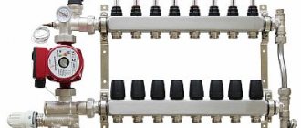
A collector is a device with which the coolant flow is distributed over individual circuits of the water floor and then returned back for heating. The collector unit looks like two pipes with holes to which the system circuits are connected.
The presence of a distribution manifold in the heated floor arrangement makes it possible to control the volume of coolant flow. One of the collector pipes is the supply pipe; hot water flows into it and the inputs of the water floor circuits are connected to it.
The return circuits are connected to the return pipe of the collector. The openings to which this connection is made are usually equipped with threaded, fitting or other connections.
The collector consists of a number of elements such as the collector itself (1 and 2), an adapter for the Mayevsky tap (3); drain valve (4); air vent (5); valve (6); bracket (7); Eurocone (8)
Various devices are also installed here with which you can regulate the coolant flow rates. The simplest version of an industrial manifold is a pipe with a connector called a Eurocone. This is a completely convenient and reliable unit, but it does not allow you to control the flow of water.
To effectively use such a device, you will have to additionally purchase and install a number of elements.
The manifold made in the DPRK is a little more complicated. In addition to the connections at the outlets, valves are installed here; no automatic means of regulating the flow are provided. This is an excellent and inexpensive option for a water floor in a small area with two or three contours of the same length.
Such a system does not require complex management. But on large areas, this type of collector will have to be supplemented with automation.
In addition, the center-to-center distance between the feed and return sections of Chinese devices does not meet the standards adopted in Europe, which can cause problems when connecting it to European-made devices.
Ball valves in such devices are sensitive to low-quality water, and over time they begin to leak. To fix the problem, it is enough to replace the O-rings, but you must take into account the fact that the need for such repairs will arise periodically.
If the operation of the water floor system is intended to be automated, it makes sense to purchase at least a manifold with control valves.
Servo drives can be installed on such valves, connected to thermostats in the rooms. This will ensure automatic control of the coolant flow in accordance with data on the air temperature in a particular room.
To automate the operation of a water heated floor system, flow meters are installed on the collector supply (indicated by a frame), and connectors for servo drives are installed on the return (blue caps at the bottom)
It is most difficult to control a water floor system in which the individual circuits vary markedly in length, but in complex systems this is usually the case. In such a situation, the optimal choice would be a manifold with flow meters installed on the supply, and sockets intended for mounting servos on the return.
Using flow meters, it will be possible to adjust the intensity of the coolant flow, and servo drives in conjunction with thermostats allow you to set the appropriate temperature on each circuit.
If there is no need for automatic control, you can purchase a supply manifold with flow meters, and a return manifold with conventional valve taps.
It happens that it is not possible to choose a collector with the number of connection sockets that corresponds to the project. Then you can take the device “with a reserve”. And the extra holes are simply closed with plugs.
This solution may be useful if you later need to add a couple more loops to the water floor system.
Common installation mistakes
The most common mistake when installing a three-way valve is that the supply and return floor circuits are incorrectly connected. For example, when floor contour pipes are connected to the inlet.
Therefore, care is required; for this, there are letter designations at the mixer outputs. If you mix up the holes, the device will not function.
In addition, it is necessary to strictly follow the manufacturer's instructions regarding the distance between straight sections before and after the screw. If this rule is violated, the functioning of the regulator will be disrupted.
DIY valve installation
We present to your attention several schemes for installing a mixing valve.
A scheme that is used mainly in boiler rooms of heating systems that are connected to a hydraulic separator or to a free-flow collector. The pump, which is located in the second circuit, ensures the necessary circulation of the coolant.
Attention! In the case when the valve is planned to be directly connected to the coolant source on the bypass, which is connected to port B, then it will be necessary to install a valve with hydraulic resistance, which will be equivalent to the same resistance of this source. . If this is not done, then the coolant flow in the segment A-B will fluctuate depending on the movement of the rod
It is worth noting that this installation scheme provides for a possible interruption of coolant circulation through the source if the installation is made without a circulation pump or hydraulic separator in the main circuit.
If this is not done, then the coolant flow in the segment A-B will fluctuate depending on the movement of the rod. It is worth noting that this installation scheme provides for a possible interruption of coolant circulation through the source if the installation is made without a circulation pump or hydraulic separator in the main circuit.
It is not recommended to connect the valve to a pressure manifold or heating networks in the absence of devices that can throttle excess pressure. Otherwise, the coolant flow will fluctuate seriously.
If the return is overheated, it is allowed to get rid of excess pressure using a jumper, which is mounted parallel to the valve mixture in the circuit.
Carrying out quantitative adjustment by changing fluid flow rates is the main function performed by this three-way thermal valve. It is used where it is possible to bypass liquid to the “return”, but stopping circulation, on the contrary, is extremely undesirable. We also present a diagram for installing a three-way separating valve:
Important! A similar connection scheme has become quite popular in water and air heating units connected from individual boiler houses. . In order to link hydraulic circuits, it is necessary that the consumer's pressure losses be equal to the losses on the valve - balancer in the bypass
The diagram shown here should be used for installation on those pipelines in which there is excessive pressure. The movement of liquid is carried out due to strong pressure, which is formed using a circulation pump.
In order to link hydraulic circuits, it is necessary that the consumer's pressure losses be equal to the losses on the valve - balancer in the bypass. The diagram shown here should be used for installation on those pipelines in which there is excessive pressure. The movement of liquid is carried out due to strong pressure, which is formed using a circulation pump.
Features of operation
When operating a heated floor mixing valve, there are special points. The main one is the mandatory installation of a filter. In addition, it is not recommended to place a mixer with a thermal head in a manifold group that serves more than one room or is located in an adjacent room. A device with a remote temperature sensor placed in a heated room is suitable.
The mixing valve is the main element in the water heated floor system. The quality of room heating depends on how correctly it works. Therefore, its selection and installation must be approached responsibly. If you are not confident in your abilities, then it is better to invite a professional.
conclusions
Installing a three-way valve is not a difficult task, but requires compliance with technical rules. Typically, mixing valves are placed in front of the mixer on the supply pipe, at the points where the bypass and return pipes are connected. The pump in the system is located next to the three-way valve.
After assembling the entire mixing unit, the reliability of the connections and the functionality of the valve is checked by a test run, based on the results of which commissioning is carried out, if necessary.
A correctly installed valve maintains a given temperature in a heated room and ensures rational coolant flow, and therefore heating efficiency.
Types of 3-way valves
All thermostatic three-way valves for heating are divided into 3 types according to their design and operating principle:
- mixing;
- dividing;
- switching.
The purpose of each of the 3 varieties can be judged by its name. The first type of valve mixes two coolant flows with different temperatures, the second one separates, the third switches water between 2 lines. It is not difficult to recognize them externally; usually the principle of operation is depicted on the body in the form of a picture. Here's what a three-way mixing valve looks like:
The nameplate from Herz clearly shows the mixing of 2 flows, which means this is a mixing valve
A similar designation appears on the separating element. As for switching taps, there may not be an image on their body, but there are significant external differences in shape.
Separating (photo left) and switching (right) 3-way valve
By mixing or separating flows, the optimal temperature of the coolant supplied to the radiators of the heating system or underfloor heating circuits is achieved. Switching is used in gas double-circuit boilers, when heated water must be alternately directed to different heat exchangers.
Controlling the operation of a heated floor system
The efficiency of heating devices depends not only on their power and adjustments, but, above all, on the condition of the heated object. If a building is not insulated enough, no system will create conditions for comfortable living in it. Walls made of porous materials such as sawn shell rock or foam concrete reduce heat loss by 20 - 25% compared to ceramic bricks; additional wall insulation and wind protection, as well as insulation of the roofing pie, give approximately the same effect.
Turning to the issue of controlling the operating mode of heated floors, it should be noted that two main approaches are used: manual control of the mixing unit and the use of automatic control systems.
The first option is used for small buildings consisting of 2 or 3 living rooms and auxiliary premises. Setting the mixing mode is done manually using an ordinary tap.
For complex, developed heating networks, this method is unrealistic due to the multifactor nature of the process and complex automated devices are used.
Heating control systems can be:
- group - their task is to convert the water temperature at the outlet of the boiler of 75 - 90 degrees into the 35 - 40 degrees required for low-temperature circuits at the inlet and control the temperature of the return flow, making adjustments to the mixing mode. Naturally, changes in weather conditions also affect the amount of heat transfer in the heating system;
- individual - the coolant flow rate for each circuit is set so that the room has a constant temperature within a given range. This is achieved either by installing a temperature sensor in the room or by monitoring the return flow temperature at the outlet of the register directly at the collector unit.
Equipment
It is impossible to display the entire variety of devices in a short article, so we will focus on some of their typical representatives:
Group controllers
Heating is controlled by applying a pulse to the servo drive of the control valve, which performs the corresponding manipulation. Up to 10 channels from sensors are installed in one controller to adjust the mixture in various circuits. Programming is possible.
Heated floor operating mode control unit
When an external temperature sensor is connected, the coolant heating temperature mode changes preventively.
Thermostats
A remote device capable of measuring temperature at the installation site and transmitting data about it to the heating system control unit. The device can transmit information both over wires and over a radio channel. It should be installed in a place protected from sunlight and away from drafts.
Room thermostat for water floor
A device for directly controlling the temperature of the coolant flow. Placed in a pipeline rupture. Usually equipped with a servomotor to control the damper. It is calculated at work at a system pressure of up to 16 atmospheres.
Three-way thermostatic valve in a heated floor control system
Servo
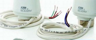
A device that actuates a valve's shut-off device (stem). The small-sized device creates a force of more than 10 kg.
Servomotor for underfloor heating valve
Water circuit installation diagrams
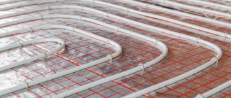
If the installation of warm water floors is carried out using a well-established, traditional technology in a clear sequence, then the installation of a heating pipe can be carried out in various variations. The main goal pursued when installing heated floors is to uniformly heat the entire area of the heated room. Laying a pipeline just the way you want means deliberately creating problem areas throughout the entire structure. The coolant tends to quickly lose temperature as it flows, so the pipes must be laid starting from the walls, then moving towards the entrance to the room or to its center. For this purpose, specially developed optimal schemes for laying the water circuit, each of which has its own characteristics.
The mixing unit and manifold are the beginning of the entire heating system. Water circuits are connected in a clear sequence. The beginning of the pipeline is to the inlet pipe, the end of the pipe is connected to the check valve.
You can install a warm water floor with your own hands, the contour of which will be laid as follows:
- pipe installation according to the snake pattern"
- laying the pipeline according to the snail pattern;
- combined scheme.
When installing heating in corner rooms, a pipe laying scheme is used for enhanced heating.
In each individual case, we can talk about the advantages of one or another scheme. For example: a snail is the simplest circuit. The bend of the pipe here reaches 900, while in a snake the heating pipe will be bent by 1800.
Where heated rooms have a linear slope, it is better to install the pipe according to the “snake” pattern. The pipeline is laid in the direction from the mixing unit towards the slope. Air pockets in this version can be easily removed, which cannot be said about a pipe laid in a snail pattern. In sloping rooms, removing air pockets can be problematic.
For large premises where it is necessary to use several water circuits of the same length for heating, the “snake” pipeline laying scheme is very convenient. Thanks to this installation method, it is possible to achieve balanced operation of the entire heating system.
Heating pipes laid on a prepared base are connected to a manifold that distributes the supply of coolant to the system. The distribution cabinet together with the mixing unit is installed either in the heated room or next to it, which significantly reduces the number of pipes and the consumption of other materials. The bends of the water pipe at the point of connection to the collector are sewn into a special protective box.
In each individual case, a certain order of laying the water pipe should be followed. When working with a snail circuit, the pipe is first laid along the perimeter of the walls, after which a turn follows from the farthest wall. In the opposite direction, the pipe is laid in a spiral, reaching the center of the heated room. For the snake circuit, the water circuit is laid out as follows. The pipe is laid along the perimeter of the walls, after which uniform bends are made in the opposite direction.
The combined installation schemes of heating pipes for heated floors, used in some cases, involve the simultaneous use of both options. One half of the room can be heated by a water circuit laid in a snake pattern, while the other part of the room will be heated by a pipe mounted in a snail pattern.
Electric cranes
Advantages:
- The main advantage of electric cranes is easy installation or dismantling.
In order to install the device, the technician does not need to be a highly qualified specialist who understands the intricacies of electrical, mechanical and simply technical crafts. Anyone can install the equipment, which reduces the cost of paying for the final result of the purchase and installation of additional materials for the thermal heating system. Photo 1. Electric actuator for a three-way valve model Elbi, Italy. - The design of the device itself expands the boundaries of control of the position of the tap with the help of two microswitches, installed conveniently and having multi-color LEDs, responsible for different temperatures, both hot or cold, and warm. Control is also simplified with a simple manual control knob, allowing you to control the temperature and set more precise heating or cooling settings.
- Another positive feature that distinguishes a three-way valve with an electric drive from a conventional one is the quick attachment of the valve due to additional fittings included in the set of provided thermal equipment. Again, installation or dismantling can be carried out by the buyer himself, without the help of specialists.
The operating principle of such a valve is not very different from a conventional one. However, there are some subtleties. Unlike a simple device, here the temperature is regulated by an electric drive, which takes temperature readings (sensor). Next, the information enters the controller, which commands the rod or ball (segment) to rise or fall to achieve the required water heating.
Drive types and selection criteria
Automatic valve with electric drive
According to the type of drive, the models are:
- Mechanical
, the separator is installed manually. To monitor temperature indicators, a thermometer is installed on each incoming pipe. - Automatic
, the movement of the membrane depends on the temperature and is carried out independently.
The drive can be:
- Thermostatic
, in which the sensitive element expands under the influence of temperature and begins to put pressure on the valve stem, mixing cold flows with hot ones. - Electrical
, in which signals are supplied from the control unit. - Cap type
, the tap is controlled by pressing the head on the drive rod; the drive is applicable when installing a floor heating system.
When choosing a three-way valve, the main thing is the type of actuator. Manual drive control is cheaper, but has few functions. Electric models are expensive and break down quickly, but their versatility does not leave most consumers indifferent. Bronze brass faucet material is durable but also expensive.
The best option is cast iron, copper.
When choosing, take into account:
- Media consumption.
- Strapping diagram.
- Operating parameters.
Flow and temperature must be indicated in the design documentation; if it is not available, the optimal water heating temperature is indicated in the passport, usually not higher than 50 degrees. Flow is taken into account when selecting a valve based on its capacity.
The type of drive must correspond to the wiring diagram.
A thermostatic valve has a simpler scheme, in which water circulates through the third pipe to the first, the boiler heats it, and only after that the coolant begins to warm up. Having heated up to the required temperature, out of three possible ones, the tap opens flows of cold water from the second pipe, replacement occurs, cold water leaves, hot water enters the tank with a heat accumulator.
The piping scheme is more complicated when an external controller is installed on the crane.
In this case, dual-drive and dual-circuit mixers will be required. The first circuit is installed next to the heat source and is thermostatic. The second drive is electric, controlled by the controller by sending sensor signals, the faucet maintains the temperature of the coolant.
An important criterion when choosing a device is the temperature range
, products, as a rule, in this case have a thermostatic drive in the piping of hot water boilers and underfloor heating systems. The range of taps depends on the purpose of the products, ranging from 20-43 grams, 35-60 grams and above. It is advised to stick to the second option when purchasing.
When installing the piping, it is worth asking how the tap is checked. If the product is new, it is not difficult to check it; the minimum temperature in the range is set in the third pipe, hot water is poured. After 15 - 20 minutes, the pipe should turn off the tap.
You can check the device in an already installed system by measuring the water temperature at the entrance to the boiler, that is, on the back side of the pipeline the value should be the same as on the thermostat.
Strapping diagram:
Large areas
Installing heated floors as the main type of heating involves installing full-fledged mixing equipment that is capable of dividing the flows into two - heated floors and central heating. Here, three-way thermostatic valves with full flow into the system are required.
Experts recommend installing one common circuit where the working fluid is pumped by a pump. At the entrance to the heated floor there is a mixing valve. It is controlled by a special temperature regulator. The mixing valve is installed between the bypass and return. A sensor at the top of the valve regulates the set temperature.
If the temperature rises, the mixing valve closes the return flow. Further circulation of the working fluid occurs in the coolants of the heated floor.
Sources
- https://ProUteplenie.com/otoplenie/termostaticheskiy-klapan-dlya-teplogo-pola-vidy-i-kak-vybrat-shemy-montazha
- https://bph-saratov.ru/otoplenie/termostaticheskij-ventil.html
- https://OtoplenieBlog.ru/oborudovanie/teplyj-pol/kak-vybrat-termostaticheskij-klapan-dlya-tyoplogo-pola.html
- https://seti.guru/termogolovka-dlya-teplogo-pola-vodyanogo
What do you think of this article?
Direct connection diagram
You have a boiler, after which all safety fittings + a circulation pump are installed. In some wall-mounted boiler versions, the pump is initially built into its body.
For floor-standing units you will have to install it separately. From this boiler, the water is first directed to the distribution manifold, and then disperses through the loops. After which, having completed the passage, it returns through the return line to the heat generator.
With this scheme, the boiler is directly adjusted to the desired temperature of the TPs themselves. You don't have any additional radiators or radiators here.
What are the main features worth paying attention to here? Firstly, with such a direct connection, it is advisable to install a condensing boiler. In such schemes, operation at relatively low temperatures for the condenser is quite optimal
In this mode it will achieve its highest efficiency
In such schemes, operation at relatively low temperatures is quite optimal for the condenser. In this mode it will achieve its highest efficiency.
If you use a regular gas boiler, you will soon say goodbye to your heat exchanger.
The second nuance concerns solid fuel boilers. When you have it installed, for direct connection to heated floors, you will also need a buffer tank.
It is needed to limit the temperature. It is very difficult to directly regulate the temperature with solid fuel boilers.
Features of choosing mixing units
Piping of the boiler and other components of the heating system is always done with standardized pipes. At the same time, each developer tries to use threaded connections of the same standard size throughout the entire pipe structure. Here, a design feature of the three-way valve may appear that may prevent the system from operating efficiently and reliably.
Despite the fact that the threaded connection diameter of the mixing unit can be quite significant, this does not indicate the actual throughput. The problem is that the inner diameter of the holes that are blocked by the control head or ball can be 4 or more times smaller than the connecting pipe. Therefore, it is imperative to review the technical documentation in the store.
The key parameter that should be taken into account when choosing a particular product is throughput. Qualified heating system developers are able to provide such a figure for guidance. But if everything was done “by eye,” you need to focus on the performance of the heating boiler. The amount of water it is capable of producing per hour or minute must be compared to the flow capacity of the valve.
Technical Specifications of Three-Way Valve
Adjusting the heating of water floors
Most often, to install water floor heating, they use a connection of heating circuits through a manifold, to which both ends of the pipeline go: one of them supplies the coolant, and the other returns it back. Hot water at the same temperature enters the inlet of each heating circuit.
Since the length of the pipelines is different, each room is heated to a different temperature. For example, for a bathroom this parameter should be 25 degrees, and for living rooms it cannot exceed 22 degrees. To add or decrease the degree of heating of the room, you need to change the amount of coolant supplied to the circuit.
The simplest way to regulate the temperature of a water heated floor is to equip the collector with special valves for the inlet and outlet (more details: “Diagram of a heated floor collector - how everything should work”). By turning their heads, you can adjust the amount of coolant supplied to each of the circuits. In this case, you have to rely only on your own feelings, and this method of adjusting the heating cannot be called convenient.
The sequence of actions is as follows:
- the control valves are tightened;
- wait for some time until the floor warms up;
- evaluate the result;
- tighten the valves again, etc.
Since the temperature outside is almost never the same for even one day, home owners have to turn the valves very often, manually.
The thermostats shown in the photo are usually placed in each room where hydronic floor heating is installed. In turn, each circuit on the coolant supply comb is equipped with servo drives. They, according to signals, increase or decrease the amount of water supplied to the circuit. Thermostats are connected to specific servos and send control commands to them.
Regulators control either the temperature of the warm water floor or the air mass in the room. At the same time, it is necessary to monitor the air temperature in the room when heating the floor surface is the only method of heating in the house.
Operating principle of a heated floor controller:
- The required temperature (floor surface or air, depending on the specific model) is set on the equipment body.
- If the parameter deviates in one direction or another, a signal is sent to the servomotors, after which the supply of coolant either increases or decreases. As a result, after a certain period of time, the temperature returns to normal.
Manifold connection to the boiler
The process of connecting a warm water floor with a comb is very simple and boils down to connecting the pipes of the heating circuits to the collector, and the collector itself to the boiler. However, there are differences in the configuration of the collector. This is what we will consider in this subsection.
The collector must be installed in such a way that it is convenient to connect the heating circuit pipes to it. So, install shut-off valves on the collector. Connect the side outlet to the pipe for both supply and return.
If you buy a ready-made manifold kit, it will already have all the necessary valves, even at the outlets of the pipes going to the boiler. The presence of taps will allow you, if necessary, to carry out repairs or temporarily disconnect one of the circuits. If you assemble the manifold yourself, then the connection of each element is assembled using a compression fitting. As a result, the heated floors will be connected to the boiler through the manifold.
To automate coolant temperature control, the following set of equipment is additionally installed in the collector:
- Pumping and mixing unit, which includes a three-way mixing valve.
- For forced circulation pump.
- Drain tap.
- Air vent.
So, instead of shut-off valves, install thermostatic control valves on the manifold. Their design contains a thermal cylinder with paraffin, which, based on the air temperature in the room, narrows or expands. These actions set the capacity of the thermostatic valve. As for the pumping and mixing unit, the principle of its operation was written above.
So, we have looked at the basic and working diagrams for connecting a warm water floor. As you can see, knowing how to properly install a water floor is not enough. It must be connected correctly. We hope that this article will help you understand the intricacies of this work. And if you already have personal experience, then leave reviews and comments at the end of this article regarding the water heated floor connection diagrams you use.
