Most homeowners choose heated floors as an additional device to the radiator circuit. In this case, various installation diagrams for water heated floors are used in a private house. Such a heating system is effective in rooms where children live, as well as in the bathroom. Schemes are selected when individually designing a house or during renovation work.
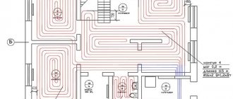
Option for a project plan in a private house
Installation diagrams for water heated floors in a private house: features and varieties
Installation of underfloor heating is carried out using a cement screed. It is performed to protect the structure from various loads. Warm pipes should not be in contact with air, but with screed elements, transferring heat to the surface.
Underfloor heating system
Installation diagrams of water heated floors used in a private house are planned and designed in accordance with calculations of heat consumption and heat loss and have the following features:
- The required amount of heat is calculated taking into account the dimensions of wall structures and methods of insulation of different surfaces. The characteristics of a certain climatic zone are also taken into account.
- Floor elements are not installed under the entire surface of the floor covering. Space remains free for the installation of heavy furniture, as well as indentations from the walls.
- Premises with an area of more than 30 square meters are divided into sectors. Each individual area is heated using a separate circuit connected to the collector.
- The distance between the pipes must be the same.
- This design requires circulation pumps.
- Installation schemes for heated floors depend on the size of the room and heating methods. If the device is used as additional heating, then the loop pitch should be 0.2-0.3 meters, and if as the main one, then the spirals should be mounted at a distance of 0.1-015 m.
- The length of the lines and the placement pitch depend on the diameter of the selected pipe.
- The height of the structure is taken into account when designing window and door openings.
Article on the topic:
Calculation of the heat of a heated floor. Without a competent project, it is almost impossible to obtain a high-quality heating system. After studying this publication, you can easily calculate the required power, diameter and pitch of pipes. Good luck!
Design of an underfloor heating system
The main floor installation patterns include: spiral, snake and zigzag. The choice depends on the specifics of the room, types of pipes and other features. For example, for large rooms, using a simple snake is not entirely correct, since the water in the circuit cools down, “cold” zones will form. While in spiral laying the supply and return pipes alternate, which will ensure more uniform heating.
Basic contour laying options
Helpful information! The diameter of the pipe should be no more than 20 mm. If the cross-section is larger, the volume of water and heating costs increase.
Water circuit installation diagrams
*
If the installation of warm water floors is carried out using a well-established, traditional technology in a clear sequence, then the installation of a heating pipe can be carried out in various variations. The main goal pursued when installing heated floors is to uniformly heat the entire area of the heated room. Laying a pipeline just the way you want means deliberately creating problem areas throughout the entire structure. The coolant tends to quickly lose temperature as it flows, so the pipes must be laid starting from the walls, then moving towards the entrance to the room or to its center. For this purpose, specially developed optimal schemes for laying the water circuit, each of which has its own characteristics.
The mixing unit and manifold are the beginning of the entire heating system. Water circuits are connected in a clear sequence. The beginning of the pipeline is to the inlet pipe, the end of the pipe is connected to the check valve.
You can install a warm water floor with your own hands, the contour of which will be laid as follows:
- pipe installation according to the snake pattern"
- laying the pipeline according to the snail pattern;
- combined scheme.
When installing heating in corner rooms, a pipe laying scheme is used for enhanced heating.
In each individual case, we can talk about the advantages of one or another scheme. For example: a snail is the simplest circuit. The bend of the pipe here reaches 900, while in a snake the heating pipe will be bent by 1800.
Note: the “snake” type water circuit can be powered by a low-power circulation pump. For a bathroom or children's room, this installation scheme looks preferable.
*
Where heated rooms have a linear slope, it is better to install the pipe according to the “snake” pattern. The pipeline is laid in the direction from the mixing unit towards the slope. Air pockets in this version can be easily removed, which cannot be said about a pipe laid in a snail pattern. In sloping rooms, removing air pockets can be problematic.
For large premises where it is necessary to use several water circuits of the same length for heating, the “snake” pipeline laying scheme is very convenient. Thanks to this installation method, it is possible to achieve balanced operation of the entire heating system.
Heating pipes laid on a prepared base are connected to a manifold that distributes the supply of coolant to the system. The distribution cabinet together with the mixing unit is installed either in the heated room or next to it, which significantly reduces the number of pipes and the consumption of other materials. The bends of the water pipe at the point of connection to the collector are sewn into a special protective box.
In each individual case, a certain order of laying the water pipe should be followed. When working with a snail circuit, the pipe is first laid along the perimeter of the walls, after which a turn follows from the farthest wall. In the opposite direction, the pipe is laid in a spiral, reaching the center of the heated room. For the snake circuit, the water circuit is laid out as follows. The pipe is laid along the perimeter of the walls, after which uniform bends are made in the opposite direction.
The combined installation schemes of heating pipes for heated floors, used in some cases, involve the simultaneous use of both options. One half of the room can be heated by a water circuit laid in a snake pattern, while the other part of the room will be heated by a pipe mounted in a snail pattern.
Construction of a heated floor
An underfloor heating system consists of laid pipes in which heated water circulates. They are installed on concrete or wooden surfaces, and covered with the selected finishing coating on top.
Warm floor in section
Hot water moves through pipes. The supply is carried out using the main heating. The air temperature under the floor rises, transferring heat to the outer surface of the floor covering. At the same time, the entire room warms up.
Design features depending on the finishing coating material
Prepare the base
Ideally, a rough screed is needed as a base, which needs to be brought into an even state. Namely, to knock down bumps and sagging if they formed during pouring. This is necessary so that you can easily lay polystyrene foam in the future. Otherwise, it will “walk” and not adhere tightly to the surface.
In principle, you can lay a heated floor cake on the ground, but it must be carefully compacted so that there is no subsidence of the same polystyrene.
Nuances of installation
The technology of installation diagrams for water heated floors in a private house is determined by the characteristics of a particular heating circuit.
Construction installation options are influenced by many parameters
The installation work of the structure has the following distinctive features:
- The base for the equipment is selected taking into account the floor covering.
1 – floor beam; 2 – longitudinal beam; 3 – logs; 4 – mortgages for pipes; 5 – pipe; 6 – finishing coat
- A damper tape is installed around the perimeter of the room. The shock-absorbing element reduces heat loss at the junction of the floor and wall surfaces.
Features of laying damper tape
- The system itself is mounted on concrete slabs in a screed.
Screed installation for water heated floors
- Waterproofing, reinforcing mesh and a layer of insulation are laid on the base.
Laying waterproofing material on the base
- Pipes are mounted to the frame using clamps or steel wire.
Installation to a frame structure
For heated floors, special seamless pipes are used. The circuit is mounted from a solid line. The pipe material must be resistant to corrosion and resistant to high temperatures.
Special pipes for the water circuit
Helpful information! Profile mats made of extruded polystyrene foam can be used as a frame and insulation. Then the canvases are covered with a layer of waterproofing.
Laying thermal insulation
After preparing the base, the next step is to lay the insulation. Expanded polystyrene acts as the main heat insulator. You can use any brand, the main thing is to maintain a density of around 30-35 kg/m3.
In our experience, the thicker you put the polystyrene foam, the better. Especially on the first floor. The minimum recommended thickness is 5 cm. But even with it, downward heat loss is observed, although insignificant. If it is possible to lay 10 cm on the ground floor, then it is better to do so. It is also advisable to glue the sheets of expanded polystyrene together (if you use two layers). For this purpose, each brand often sells special glue along with thermal insulation.
If you use polystyrene with bosses, then you can immediately begin laying the heated floor. If not, then read on.
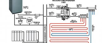
Features of connecting the structure to a heat source
In a floor circuit, most often the average coolant temperature is 35-40 degrees. Installation diagrams for water heated floors in a private house operate using forced mixing of flows. Part of the coolant from the return flow passes into the supply circuit.
Thermostat connection diagram
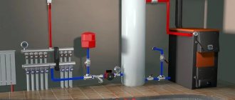
Gas boilers are equipped with special automation. Solid fuel units require a more complex device. They are equipped with circulation pumps and a special buffer tank. In this case, more complex combustion adjustment is used.
Location of the boiler in a separate room
Electric boilers are considered the best option for underfloor heating systems. Special automation allows you to maintain the desired temperature without loss of thermal power.
Electric boiler in operation
Helpful information! To heat small houses, a direct connection to an electric boiler is used. In cottages with a large area, a special distribution comb is used.
Three-way valve
The device is installed at the point with the highest temperature (on the supply pipe). The VTP connection diagram in practice looks like this:
Feed line
Boiler → 70 °C → Three-way mixer → Circulation pump → 45 °C → Warm floor
After the pump, a temperature sensor is installed on the supply pipe. It determines the degree of heating of the incoming water. Next comes the thermostatic valve.
Advantages and disadvantages of schemes
Installation diagrams for water heated floors in a private house have the following advantages compared to other heating options:
- In homes with large areas they help reduce energy costs.
- Provide uniform heating of the room.
- The device is characterized by increased safety, since there is no risk of burns or injury.
- Pipes do not spoil the interior of the room.
- Warm floors go well with many finishing materials.
- Possibility of different connection options.
Installation of heated floors in cottages is becoming increasingly popular.
The disadvantages include the large amount of time required to install the system. If leaks appear, you will have to remove most of the floor covering, including the screed.
Pressure testing of floors
An important point in our instructions. After laying the pipe, all circuits need to be pressurized. This is done in order to finally verify the tightness of the pipes and the absence of defects in them.
The system can be pressurized with either air or water. If you are sure that you will move into the house before winter, then you can resort to water pressure testing. In other cases, it should be pressurized with air. Pump the pressure around 4 bar and watch it “hold”. If the pressure drops a little, it's okay. This is often due to changes in temperature. But if the decline is significant, then you should look for the leak.
Designing schemes for heated floors in an apartment
Designing installation diagrams for water heated floors in a private house differs from an apartment project. After installation, you cannot make changes to the radiator layout. Installation of floor structures powered by centralized heating is carried out during the construction stage by special organizations.
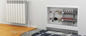
Installation of the structure in the apartment
In apartments, the coolant is supplied through pipes through a separate riser, and not from the radiator heating riser. The water is heated in a special heat exchanger. If the project initially does not contain data on the installation of underfloor heating, then the connection of a new circuit must be approved by the management company.
Connection to distribution manifold
Helpful information! After agreeing on the project and obtaining permission, a heat exchanger is installed, and an expansion tank, circulation pump and safety group are installed. For multiple circuits, a collector unit is used.
Collector connection diagram
The choice of a ready-made mechanical or automatic collector model depends on the characteristics of the heating system.
The first type of control module is recommended to be installed for heated floors without a radiator, the second can be used in all other cases.
According to the diagram, the assembly of the distribution comb for heated floors is carried out as follows:
- Installation of the frame. The following can be selected as the installation area for the collector: a prepared niche in the wall or a collector cabinet. It is also possible to mount directly to the wall. However, the location must be strictly horizontal.
- Connection to the boiler. The supply pipeline is located at the bottom, the return pipeline is located at the top. Ball valves must be installed in front of the frame. They will be followed by a pump group.
- Installation of a bypass valve with a temperature limiter. After this, the collector is installed.
- Hydraulic test of the system. Check by connecting to a pump, which helps build up pressure in the heating system.
In a mixing unit, one of the required elements is a two- or three-way valve. This device mixes water flows of different temperatures and redistributes the trajectory of their movement.
If servo drives are used to control the manifold thermostats, then the mixing unit equipment is expanded with a bypass and bypass valve.
Prices for installation work of heated floors
Installation diagrams for water heated floors made in a private house may have different costs. It will include materials, preparatory and installation work, as well as connection and strength testing of circuits. The cost of work per square meter varies from 1,500 to 3,000 rubles. The price is also affected by the type of base and the quality of the equipment.
Installation of pipes on a wooden base
Helpful advice! It is recommended to purchase ready-made sets of equipment for underfloor heating. Many manufacturers offer a free calculation of the entire system.
Useful tips
The density of the pipeline is determined by the required level of heating of the room. Near walls and entrance doors, denser installation is performed. In this case, the distance from the highway to the wall should be more than 12 cm. The length of one circuit should not be more than 100 meters. In addition, highway joints are made using metal sleeves. The manifold with gearboxes are placed in a special distribution cabinet, for which you need to select a location in advance.
Comfortable living conditions
The quality of installation diagrams determines the complete heating of the room and the creation of a favorable microclimate in the house. Good luck with the renovation!