From the author: Hello, dear friends! A home heating system with two boilers is one of the most common situations. Gas and electric boilers provide comfort to households and do not require frequent maintenance, while solid fuel boilers help reduce costs and save the family budget from unnecessary expenses.
How to correctly connect two boilers to one heating system, in series or in parallel, are there any analogues for connecting other types of boilers, and on what principle will the work take place? We will try to answer all these questions in today’s article.
Connecting an electric boiler to the heating system
piping of an electric heating boiler Electric heating convectors: how to choose - little tricks
To reduce the amount of electricity consumed, it is advisable to resort to the following scheme:
- install a heated floor system that distributes heat evenly throughout the room;
- install a heat accumulator - a heat-insulated storage tank. In it, the water will be heated at night, when a lower electricity tariff is in effect, and during the day it will slowly cool, releasing heat into the room (more details: “Correct heating scheme with a heat accumulator”).
Connecting an electric boiler to the heating system: instructions
Rules for calculating equipment power
One of the main characteristics of a boiler is its power. It determines how well the equipment will cope with heating the room on the coldest days.
It is necessary to clarify right away: the desire to spend as little money as possible is unreasonable. Things like drawing up a heating system project and performing thermal calculations are best left to professionals. If you hire an amateur or try to make the calculations yourself, this may result in new expenses in the future. You need to think through everything carefully and enlist the help of highly qualified specialists: then the cost of the boiler, radiators and other equipment will cost you much less.
In order to approximately calculate the boiler power required to provide hot water supply and to heat the building, you can use special design standards.
It is also necessary to take into account:
- Climate zone.
- Total number of doors and windows.
- Materials used to build housing.
- The total number of residents living in the house.
- Number of floors and other factors.
Many people believe that it is necessary to select a boiler for a home based on one kilowatt per ten square meters of housing. This is partly true. However, using new engineering equipment, as well as modern building materials, you can reduce heat losses and thereby increase the efficiency of your heating equipment.
How to connect a solid fuel boiler
The canonical connection diagram for a solid fuel boiler contains two main elements that allow it to function reliably in the heating system of a private home. This is a safety group and a mixing unit based on a three-way valve with a thermal head and a temperature sensor, shown in the figure:
Note. The expansion tank is not shown here, since it can be located in different places in different heating systems.
The presented diagram shows how to connect the unit correctly and should always accompany any solid fuel boiler, preferably even a pellet one. You can find various general heating schemes anywhere - with a heat accumulator, an indirect heating boiler or a hydraulic arrow, on which this unit is not shown, but it must be there. This is explained in more detail in the video:
The task of the safety group, installed directly at the outlet of the supply pipe of a solid fuel boiler, is to automatically relieve pressure in the network when it rises above a set value (usually 3 Bar). This is done by a safety valve, and in addition to it, the element is equipped with an automatic air vent and a pressure gauge. The first releases the air appearing in the coolant, the second serves to control the pressure.
Attention! It is not allowed to install any shut-off valves on the section of the pipeline between the safety group and the boiler
How the scheme works
The mixing unit, which protects the heat generator from condensation and temperature changes, operates according to the following algorithm, starting from kindling:
- The firewood is just starting to burn, the pump is on, the valve on the side of the heating system is closed. The coolant circulates in a small circle through the bypass.
- When the temperature in the return pipeline rises to 50-55 °C, where the attached remote-type sensor is located, the thermal head, at its command, begins to press the three-way valve stem.
- The valve slowly opens and cold water gradually enters the boiler, mixing with hot water from the bypass.
- As all the radiators warm up, the overall temperature increases and then the valve closes the bypass completely, passing all the coolant through the heat exchanger of the unit.
This piping scheme is the simplest and most reliable; you can easily install it yourself and thus ensure the safe operation of the solid fuel boiler. There are a couple of recommendations regarding this, especially when piping a wood-burning heater in a private house with polypropylene or other polymer pipes:
- Make the section of the pipe from the boiler to the safety group from metal, and then lay plastic.
- Thick-walled polypropylene conducts heat poorly, which is why the surface-mounted sensor will openly lie, and the three-way valve will lag. For correct operation of the unit, the area between the pump and the heat generator, where the copper flask is located, must also be metal.
Another point is the installation location of the circulation pump. It is best for him to stand where he is shown in the diagram - on the return line in front of the wood-burning boiler. In general, you can install the pump on the supply side, but remember what was said above: in an emergency, steam may appear in the supply pipe. The pump cannot pump gases, so if steam gets into it, the circulation of the coolant will stop. This will speed up a possible explosion of the boiler, because it will not be cooled by water flowing from the return.
Way to reduce the cost of strapping
The condensate protection circuit can be reduced in cost by installing a three-way mixing valve of a simplified design that does not require connecting an overhead temperature sensor and thermal head. It already has a thermostatic element installed, set to a fixed mixture temperature of 55 or 60 °C, as shown in the figure:
Special 3-way valve for solid fuel heating units HERZ-Teplomix
Note. Similar valves, which maintain a fixed temperature of mixed water at the outlet and are intended for installation in the primary circuit of a solid fuel boiler, are produced by many well-known brands - Herz Armaturen, Danfoss, Regulus and others.
Installing such an element definitely allows you to save on piping the TT boiler. But in this case, the possibility of changing the temperature of the coolant using a thermal head is lost, and its deviation at the output can reach 1-2 °C. In most cases, these shortcomings are insignificant.
Water heater protection
Indirect heating boilers and electrical storage devices that prepare water for household needs also require protection. In this case, the danger is represented by pressure surges in the water supply and expansion of the liquid in the tank due to heating. To prevent the tank from leaking, a boiler safety group is installed at the water supply, consisting of the following parts:
- brass body;
- a check valve that does not allow water to flow from the container back into the pipe;
- safety valve that relieves excess pressure;
- ball valve to close the hot water supply line.
In addition, indirect heating boilers are equipped with an automatic air vent mounted in the upper part of the tank and a dial temperature meter. A pressure gauge is optionally installed on the unit.
Hydraulic arrow in a parallel connection system
A hydraulic arrow is a device that provides hydraulic isolation of flows supplied to individual circuits of the heating system. It plays the role of a buffer tank, receiving the flow of coolant heated by the boilers and distributing it to consumers in a branched system.
Often the volume of coolant required for them differs, the speed of movement of the heated water and its pressure differ. And in the situation under consideration, the movement of heated water from each of the boilers also stimulates its own circulation pump.
When the powerful pump is turned on, the coolant is unevenly distributed throughout the circuits. So, the task of the hydraulic gun is to equalize this pressure. Due to the fact that there is virtually no hydraulic resistance inside it, it will freely receive and distribute coolant flows from both boilers.
Let’s figure out whether it is really necessary in a parallel system for connecting 2 boilers, especially since if you buy and install a hydraulic separator with the help of a specialist, and not with your own hands, the total amount will be unpleasantly surprising.
The device is a piece of pipe with pipes, hollow or with filter meshes to remove bubbles and filter out incoming contaminants. It can be placed in any position, but more often vertically, with an air vent on top and a shut-off valve on the bottom for cleaning. A hydraulic arrow is installed between the boiler and heating circuits
In the classic connection scheme, a hydraulic separator is usually not required, since the conflict of 2-3 pumps can be equalized without this device. Accordingly, if you have 2 boilers that are used exclusively as a backup and there are no more than 3-4 pumps in the system, there is no particular need for it.
But if there are more forced circulation circuits or heating boilers operate simultaneously at full power, it is best to install this device. Again, it is unknown whether you will use the second boiler permanently or only in backup mode, so it is better to be safe.
Selecting a location for heating equipment
In this section we will tell you which boiler to choose for heating your home. Namely, let's talk about the types of heating equipment. In addition to the classification of boilers according to the energy carrier used, according to the number of circuits, there are also wall-mounted and floor-standing boilers.
Manufacturers mainly produce electric boilers in a wall-mounted version. Some gas models are also hung on the walls.
However, if you live in a large house, then you should pay attention to floor-standing options: they have great power, but also occupy a large area. As mentioned earlier, ideally, a separate room – a boiler room – needs to be allocated for heating equipment. In mounted boilers, heat exchangers are made of copper and steel
Floor-standing units have a longer service life, since these elements in such models consist primarily of cast iron. It is for this reason that the service life of mounted electric boilers, as a rule, does not exceed ten years
In mounted boilers, the heat exchangers are made of copper and steel. Floor-standing units have a longer service life, since these elements in such models consist primarily of cast iron. It is for this reason that the service life of mounted electric boilers, as a rule, does not exceed ten years.
In addition, complex electronics can fail due to sudden power surges in the network. Therefore, if you decide to purchase a wall-mounted boiler, do not forget to buy a voltage stabilizer.
Boilers designed for walls are very light weight and very compact, but they are very weak compared to their floor-standing counterparts. This disadvantage is especially felt on heating devices with a dual-circuit system. Such boilers heat the room very poorly.
You need to pay attention to wall-mounted heating devices only if the living space you will be heating does not exceed two hundred square meters. Water consumption should not be more than fifteen liters per minute. If you have one of the characteristics higher than stated, then you should look for other options
If you have one of the characteristics higher than stated, then you should look for other options.
It must be said that, regardless of the heated area, the majority of buyers purchase floor-standing boilers. Since such units have a cast iron heat exchanger installed, which has lower requirements for the quality of the supplied current and also lasts longer.
Power Supply Requirements
Such a consumed load on the electrical network requires a dedicated line to connect the converter.
The power cables to it are laid directly from the metering device (electricity meter). For emergency or scheduled generator shutdown, automatic switches are used, which in parallel act as a fuse in the event of a short circuit.
It is possible to connect models with a power of up to 9 kW to a single-phase network; more powerful equipment operates on three phases.
Please note: the boiler must be connected to a grounded electrical network
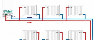
Two-pipe connection diagram with boiler
Connecting a double-circuit gas boiler.
To connect the heating system, a two-pipe circuit can be used. The coolant here will move up along one separate line, and then return back to the boiler along a completely different one. In such a system, as a rule, forced circulation of the coolant is used, i.e., the installation of a circulation pump is required. But the system warms up much faster, and it loses less heat during transportation to the radiators.
This reduction in heat loss is due to the fact that a special heat regulator can be installed for each radiator, without causing any damage to the other components of the entire system. The installation of this system with a boiler is very different from a single-pipe system, for which installing regulators is simply impossible. An example of such a boiler connection diagram is shown in Fig. 3. For installation, according to this boiler diagram, you can use different types of pipes, radiators, everything warms up evenly and correctly.
Direct connection diagram for a gas double-circuit boiler.
Connecting the system to the boiler is carried out in several ways, one of them involves supplying coolant to and from the radiator from one side of the equipment. On the other side, regular plugs are installed, the return pipe goes from below, while the coolant flows from above. But if the radiator has more than 15 sections, then such a scheme is not used due to large heat losses. In this case, a connection diagram is used when the coolant is supplied from below to different sides of the equipment. This method is effective when all the pipes of the heating system are laid under the floor, the outlets are organized only in the places where the heating radiators are installed. But there are also some disadvantages: the coolant may not completely warm up the radiator from bottom to top, so cast iron radiators are not used; preference is given to panel radiators, which are heated best.
When the lower connection diagram is performed, it is also necessary to provide for an emergency shutdown from the coolant supply. This allows you to avoid leaks if the entire heating system malfunctions. If all conditions are met correctly, then heat loss will be minimized, it will be approximately equal to 2%.
Connecting a heating boiler and completing the entire wiring of the house system is an important and complex process. It is necessary to strictly follow all standards and recommendations, having previously calculated which elements should be included in the connection diagram and what type of heating wiring to choose.
Piping of a wall-mounted double-circuit gas boiler
Modern double-circuit gas boilers are distinguished by their complexity of design. They are ready-to-use devices, ready for integration into heating systems. They usually contain:
- Sealed membrane tanks (the average volume is 8-10 liters, which is quite enough for the heating circuit of a private house);
- Circulation pumps - no need to purchase them separately;
- Safety groups - safety valves, automatic air vents, as well as pressure gauges or thermomanometers are installed here.
Thus, they do not need to purchase additional equipment.
Nevertheless, in the piping schemes of double-circuit heating boilers, additional circulation pumps and air vents can still be used - it all depends on the complexity of the systems being installed.
Water filtration
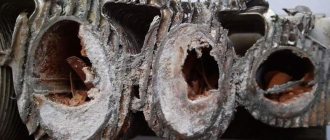
Water filters can also be classified as piping heating boilers, both electric and gas. They protect equipment from damage resulting from simple blockages. Filters purify water mechanically, trapping small fractions of contaminants, and also provide water softening. The last point is especially important, since high salt content causes clogging of heat exchangers with lime deposits.
The simplest filters are based on ion exchange resin. They replace metal atoms in salts, making the water softer. As a result, the likelihood of limescale deposits on the inside of the boilers is reduced. But before buying filters, it is recommended to check the hardness using special test strips. Membrane filter systems are considered the most reliable, but they are expensive.
Including a filter in the heating boiler piping circuit allows you to reduce the cost of servicing heat exchangers, which involves cleaning them with special liquids - a procedure that is expensive and requires calling a specialist.
Collectors and hydraulic arrows
These devices are used to distribute coolant over several separate circuits. Collectors are installed in the amount of two pieces - one on the supply pipe, and the second on the return pipe. Heating circuits - room radiators, cascades of in-floor convectors, as well as heated floors - are connected to the collector through separate circulation pumps. The cooled coolant returns to the return manifold and is returned through one pipe to the boiler. This heating piping scheme is used in large households.
The hydraulic arrow resembles a manifold in its design, but is connected to two pipes at once. It is installed strictly vertically. In its upper part there is a hot coolant, and in the lower part there is a cooler one. By making inserts, you can distribute the coolant among individual circuits in accordance with its temperature. The radiators are usually connected to the upper part, and heated floors are connected to the lower part.
In what cases are two boilers installed?
The decision on the need to install a second device is made when the existing one cannot cope with the required heat load. The added boiler eliminates the lack of equipment power.
Installation diagram of a pair of boilers
There are other indications for simultaneously connecting two boilers to the heating system:
- errors in determining the thermal power of boiler installations;
- expanding the area of the house to be heated;
- increasing the capabilities of the heating source;
- limited volume of main fuel.
Homemade electric heating boilers
Having the skills to work with metal, having the necessary material and tools, it is easiest to make homemade electric boilers - electrode or heating elements. If a heating element is used as an electricity converter, then you need to make or select a steel housing in which it will be installed. All other components - regulators, sensors, thermostat, pump and expansion tank are purchased separately in specialized stores. Electric boilers can be used in closed or open heating systems.
What is needed and how to make a 220V electric heating boiler with your own hands, efficient and reliable?
You need a steel container in which one or more heating elements are placed in accordance with the drawings or sketches for the product being created. Even at the stage of the project for do-it-yourself heating boilers, the drawings should provide for the possibility of quickly and easily replacing a burnt heating element. For example, the body can be made of a steel pipe with a diameter of 220 mm with a body length of about 0.5 m. Flanges with supply and return pipes and seats in which heating elements are installed are welded to the ends of the pipe. The circulation pump, expansion tank and pressure sensor are connected to the return line.
Features of power supply of electric boilers
Heating elements consume significant power, usually more than 3 kW. Therefore, for electric boilers you need to create a separate power supply line. For units with a power of up to 6 kW, a single-phase network is used, and for higher power values, a three-phase network is required. If you equip a homemade heating boiler with a heating element with a thermostat and connect it through RCD protection, then this is an ideal option. When installing conventional heating elements, the thermostat is purchased and installed separately.
Electrode heating boilers
Boilers of this type impress with their extreme simplicity. It is a container in which an electrode is installed; the second electrode is the boiler body. Two pipes are welded into the container - supply and return, through which the electrode boiler is connected to the heating system. The efficiency of electrode boilers is close, like that of other types of electric boilers, to 100% and its real value is 98%. The famous Scorpion electrode boiler is the subject of heated debate. Opinions are extremely varied, from excessive admiration to complete denial of use for heating circuits.
It is believed that electrode boilers were designed for heating submarines. Indeed, the manufacture of heating boilers requires a minimum of materials, sea water with dissolved salts is an excellent coolant, and the hull of the submarine, to which the heating system is connected, is an ideal grounding. At first glance, this is an excellent heating circuit, but can it be used for heating homes and how to make an electric heating boiler with your own hands, repeating the design of the Scorpio boiler?
Electrode boiler Scorpio
In electrode boilers, the coolant heats the current passing between the two electrodes of the boiler. If distilled water is poured into the system, the electrode boiler will not work. There is a special salt solution for sale for electrode boilers with a specific conductivity of about 150 ohm/cm. The design of the unit is so simple that making a Scorpio electric boiler with your own hands, if you have the necessary skills, is quite simple.
Two pipes are welded to this pipe for connection to the heating system. Inside the device there is an electrode isolated from the body. The boiler body plays the role of a second electrode; the neutral wire and protective grounding are connected to it.
Disadvantages of electrode boilers
The main disadvantage of electrode boilers is the need to use saline solutions, which adversely affect radiators and heating pipelines. The heating system may require a complete replacement of radiators, especially aluminum ones (more information about which you will read here), and piping within a few years. Circulation pumps that are designed to work with antifreeze or clean water are at great risk. The second huge drawback is that electrode boilers require ideal protective grounding of the housing, otherwise they pose a huge risk of electric shock. It is prohibited to sell and install such equipment in foreign countries!
Climate
0 votes
+
Vote for!
—
Vote against!
The gas boiler has been purchased, the gas main has been installed, the heating has been installed, the most important thing remains - to assemble it all into a single system. Connecting a gas boiler is not such a simple task, and it’s not even that gas boilers are high-tech equipment, and most importantly, dangerous equipment, the main problem is different: there are too many different options and connection schemes. The method, order of installation and connection of highways depends on individual conditions. Therefore, it is strongly recommended that the connection, start-up and adjustment of the gas boiler be carried out by an authorized service center. In addition, connecting the boiler yourself will void the manufacturer’s warranty. But situations are different, so in this article we will tell you the main universal points for connecting gas boilers. Please note that the instructions for your boiler are of higher priority than any article on the Internet.
- Gas boiler connection diagram
- Connecting a single-circuit gas boiler
- Connecting a double-circuit gas boiler
- Connecting heating to a gas boiler
- Electrical connection of a gas boiler
- Connecting a gas boiler to the chimney
- Connecting the boiler to a gas boiler
- Connecting the boiler via a three-way valve
- Connecting the boiler via an additional pump
- Connecting the boiler and heating circuits via a hydraulic arrow
- Connecting a thermostat to a gas boiler
Gas boiler connection diagram
There are several schemes for connecting gas boilers. Which one to use depends on how the heating system is designed - open or closed, the coolant in it moves by gravity or using a pump, has one high-temperature radiator circuit or several circuits, among which there is a low-temperature “warm floor”. Also important is the type of boiler - single-circuit or double-circuit, with an open combustion chamber or with a closed one, convection or condensation.
Connecting a single-circuit gas boiler
A single-circuit boiler is equipped with only one heat exchanger, which heats water for one circuit. Initially, such boilers were used exclusively for space heating, but today they can be successfully used for hot water supply by adding an indirect heating boiler to the connection diagram. Single-circuit boilers come in wall-mounted and floor-mounted versions, which one depends on the power generated. Single-circuit floor-standing boilers are more powerful and heavier than double-circuit boilers; they can be used to heat a large country house and provide households with hot water.
The peculiarity of connecting a single-circuit boiler is that only two pipes with coolant can be connected to it - one will send it into the boiler for heating, and the other will leave it heated.
Connection diagram for a single-circuit gas boiler to heating.
In the option presented above, the coolant will circulate through the heating system of the house and return to the boiler for additional heating. A safety valve and expansion tank are necessary to relieve excess pressure from the system.
Connection diagram for a single-circuit gas boiler to heating and an indirect heating boiler.
This diagram shows the simplest way to connect indirect heating to a boiler - through a three-way valve.
An indirect heating boiler is a thermally insulated container that contains water for sanitary needs. It is this water that we need to heat. For this purpose, a spiral-shaped heat exchanger is built inside the boiler, through which hot coolant water passes.
In this scheme, heating water for DHW (hot water supply) is a priority. When the sensor on the boiler is activated that the water has cooled down, the three-way valve is activated and all the coolant heated in the boiler rushes into the boiler. There it gives up its heat to the water and returns to the boiler for additional heating. The circulation of boiler-boiler-boiler will continue until the water inside the boiler is heated to the required temperature. After this, the three-way valve is activated, and the coolant from the boiler flows into the heating system and will circulate according to the boiler-heating-boiler circuit until the water in the boiler cools down.
The entire time the water in the boiler is heating up, no coolant circulates through the heating system. How long it takes to heat up a boiler directly depends on its capacity. For example, a 200 liter boiler (for a large family) filled with cold water heats up within 6 hours. But reheating this boiler will take 40 - 50 minutes. Heating a smaller boiler, for example, 80 liters, takes only 10 - 20 minutes. This time does not significantly affect the overall temperature in the house; in such a short period it does not yet have time to cool down.
Connecting a double-circuit gas boiler
A double-circuit boiler differs from a single-circuit boiler in that it has two heat exchangers: one is the main one, which heats water for heating, and the second is an additional one, which heats water for hot water supply. Most often, such boilers are a high-tech boiler room, in which everything is provided and automated, and are wall-mounted.
Pay attention to the photo, which shows the insides of a double-circuit boiler. 5 pipes are connected to it (from right to left): 1 – a pipe with coolant from the heating system, which goes for additional heating, 2 – a pipe with cold water, which goes into the heat exchanger to heat the water for hot water supply, 3 – a gas pipe, 4 – a pipe with hot water for domestic hot water, 5 – pipe with hot coolant for the heating system.
All automation of a double-circuit boiler is located inside. By default, the coolant heated in the boiler by the main burner is sent to the heating system and returned cooled back to the boiler. This is how the boiler-heating-boiler circulation occurs. But as soon as someone opens a hot water tap on one of the consumers, cold water begins to flow into the boiler through pipe 2. The three-way valve immediately redirects the coolant, and it does not leave the boiler, but the main heat exchanger circulates - an additional heat exchanger for heating water is the main heat exchanger. The coolant heats the water for domestic hot water while it is being used. As soon as the tap is closed, the coolant begins to circulate through the heating system again.
Connection diagram for a double-circuit gas boiler directly.
As practice has shown, a double-circuit boiler is not capable of providing a large amount of water for domestic hot water, no more than one consumer - a kitchen or a shower, and even then the water will not be too warm. The boiler simply will not have time to heat it to the required volume. That is why they are used only in small families, and to heat larger quantities of water, a boiler is added to the system.
Connection diagram for a double-circuit gas boiler with an indirect heating boiler.
According to the presented diagram, the coolant will only heat the water in the boiler, and the water supply system itself to the second circuit will be closed. This trick can significantly increase the durability of a double-circuit boiler, which suffers greatly from hard tap water. The additional heat exchanger for domestic hot water becomes clogged and fails in about a year. That is why circulation of clean coolant in the secondary circuit is a more economical option. But then what is the point of using a double-circuit boiler if you can install a single-circuit boiler of greater power? It will be both more profitable and practical.
Connection diagram for a double-circuit boiler with a boiler/storage system.
Connecting a wall-mounted gas boiler paired with a conventional electric boiler as a storage tank for hot water is also possible. In this case, hot water from the boiler will flow into the boiler, and when its quantity decreases to a critical point (set automatically), the boiler will again heat water to fill the boiler. It is also possible that the boiler is filled with hot water from the boiler, and its further temperature is maintained using a heating element.
We have looked at universal connection diagrams for gas boilers, now let’s move on to the procedure for installing pipes and electrics.
Connecting heating to a gas boiler
Despite the fact that the diagrams above indicate where the inlet pipe is connected and where the outlet pipe is connected, be sure to read the instructions for your gas boiler. The location of the pipes may vary depending on the model and manufacturer.
First, a few words about the heating system itself. If it has already been used before, and now you are just changing the boiler, then you need to drain the coolant from the system and be sure to rinse it several times. Many different salts settle on the walls of pipes and heating radiators; so that they do not clog the fragile heat exchanger of the boiler, it is better not to be lazy and flush the system.
Both water and antifreeze can circulate in the heating system. Whether it is possible to use antifreeze specifically with your boiler, be sure to look in the technical documentation. Sometimes boiler manufacturers themselves recommend certain brands of antifreeze or even produce it themselves. You should not ignore such recommendations.
It makes sense to use antifreeze as a coolant in the heating system only if you live in the house on short visits and turn off the boiler when you leave for a long time. In this case, the water in the pipes may freeze, but the antifreeze will not. But if you live in the house all the time and do not turn off the boiler in cold weather, then it makes sense to use water as a coolant. The reason for this is the disadvantages of antifreeze: low heat capacity, high viscosity and coefficient of thermal expansion. For the entire system, this threatens that with antifreeze it is necessary to use a boiler and pumps of higher power, a storage tank of larger capacity and heating radiators of a larger area.
The use of water is also supported by the fact that modern gas boilers can be set to safety mode, when the coolant cools down to +5 °C, the boiler heats it up again.
The heating connection diagram to the boiler is as follows::
- Circulation pump (if necessary).
- Ball valve.
- Coarse filter.
- Ball valve.
- American quick connector.
The circulation pump is always installed on the “return” side. Ball valves are necessary to easily disconnect the system from the boiler without draining the coolant, as well as to quickly remove the filter for maintenance and cleaning. A coarse filter in the heating system is necessary in order to protect the boiler heat exchanger from clogging with salts; it is placed directly in front of the boiler, preferably on a horizontal section with a sump/catcher downwards. If it is not possible to install the filter on a horizontal section of the pipe, then install it on a vertical one. The direction of coolant flow must coincide with the direction of the arrow on the filter housing.
The pipe with the hot coolant coming from the boiler must be connected to the boiler pipe using an American quick-release coupling and a shut-off ball valve must also be installed.
It is necessary to install ball valves on the inlet and outlet pipes with coolant to drain coolant from the system for the summer period or for repair work.
Connection diagram for DHW to a double-circuit boiler:
- Coarse filter.
- Ball valve.
- Fine filter or magnetic filter.
- Ball valve.
- American quick connector.
To maximize the service life of the additional heat exchanger of a double-circuit boiler and protect it from scale, it is necessary to install coarse filters and a magnetic filter on the cold water supply pipe. If a coarse filter has already been installed earlier - before the water meter, then installing it in front of the boiler does not make sense.
The outlet pipe with hot water must be connected to the pipe using an American ball valve; it is advisable to install a check valve.
All connections must be sealed with tow or FUM tape, or even better with a special plumbing paste.
Electrical connection of a gas boiler
Modern gas boilers come with two options for connecting to the electrical network - a cable with a plug for connecting to an outlet and a three-core insulated cable. Whatever option you come across, in any case you should adhere to this rule: the gas boiler is connected through an individual circuit breaker directly to the panel and it is imperative to take care of grounding. It is also advisable to use voltage stabilizers or backup power supplies in case of power outages.
The circuit breaker is installed near the boiler so that it can be turned off quickly and easily. Even if the boiler has its own cable with a plug, you should make a personal socket for it, to which power is supplied through a circuit breaker.
be grounded to a gas or heating pipe. To ensure high-quality grounding, it is necessary to equip either a grounding loop or a point grounding. For the latter, there are ready-made universal modular grounding kits on sale (ZZ-000-015), the installation of which will take an area of 0.5x0.5 m in the basement of the house, underground or on the street next to the house. The resistance of the ground loop for a heating boiler should be no more than 10 Ohms. You may find other figures in different sources, but gas services require exactly these indicators - no more than 10 ohms. This is necessary for safety reasons and is due to the fact that overhead power poles for the most part do not have re-grounding.
Connecting a gas boiler to the chimney
Gas boilers are different - some require a regular chimney, others require a coaxial one, and others (parapet boilers) do not need one at all. Therefore, read the instructions for your boiler. Moreover, most often the gas boiler already comes with a chimney; it just needs to be installed correctly.
Rule one - the diameter of the boiler chimney must be equal to or greater than the diameter of the outlet pipe in the boiler .
Most often, the diameter of the chimney depends on the power:
- up to 24 kW – 120 mm.
- 30 kW – 130 mm.
- 40 kW – 170 mm.
- 60 kW – 190 mm.
- 80 kW – 220 mm.
- 100 kW – 230 mm.
Conventional chimneys extend upward, 0.5 m above the ridge of the house. They can be installed both inside the wall of the house, and inside the house itself or behind its wall. No more than three bends on the pipe are allowed. The first section of the pipe connecting the boiler to the main chimney must be no more than 25 cm. The pipe must have a closing hole for inspection cleaning. Boilers with conventional chimneys and an open combustion chamber require a large air flow; this can be provided either by an open vent or a separate supply pipe.
Rule two - the chimney must be made of roofing sheet or other acid-resistant material . The same goes for short sections, turning elbows and other things. The boiler cannot be connected to the main chimney using corrugated pipes; a brick chimney cannot be used. As a result of gas combustion, steam is formed, saturated with sulfuric and other acids; during condensation, the acids precipitate and corrode the walls of the chimney.
Rule three - the coaxial chimney is mounted horizontally and discharges directly into the wall . This type of chimney is a pipe within a pipe. The inner pipe removes steam from the boiler, and the outer pipe carries air into the combustion chamber. This allows you to heat the air and increase the efficiency of the boiler.
The coaxial chimney should extend at least 0.5 m from the wall of the house. If the boiler is ordinary, then the chimney pipe should have a slight slope towards the street. If the boiler is a condensing boiler, then the slope should be towards the boiler - then the condensate will flow into a special tube - a siphon, which must be drained into the sewer. Usually in condensing boilers everything is described in the instructions. The maximum length of a coaxial chimney is 3 - 5 m; the more turns or bends, the shorter the permissible length.
Rule four - a parapet gas boiler is installed strictly according to the scheme near the outer wall . The coaxial baffle is most often located at the back of the boiler, rather than at the top.
The gas boiler usually comes complete with all the necessary decorative wall linings, clamps and other elements.
Connecting the boiler to a gas boiler
As mentioned above, the boiler is connected to a gas boiler to provide hot water. It can be connected to both a single-circuit and double-circuit boiler. There are several connection diagrams and those proposed below are only the most common.
Connecting the boiler via a three-way valve
This scheme has already been described above. A three-way valve is installed on the heating supply line, a pipe runs from it to the indirect heating boiler itself, where it is connected to the pipe using an “American” one. The pipe with the cooled coolant from the boiler crashes into the heating “return” line. For ease of use of the boiler, the outlet pipe must also be connected to the “American” pipe.
If the safety group, pump and expansion tank are located directly in the boiler, such as in wall-mounted boilers, then the three-way valve is controlled by the boiler itself, to which a signal is sent from the boiler thermostat (must be connected).
If the boiler is floor-standing, then you can connect the thermostat directly to the three-way valve, then control will occur directly.
Connecting the boiler via an additional pump
This connection diagram also assumes DHW priority. It uses two pumps: one for the heating system, the other for the boiler circuit.
A thermostat is installed on the boiler, which signals a decrease in the DHW temperature, the heating pump is turned off and the boiler pump is turned on. It is necessary to install check valves after the pumps in the system to eliminate the possibility of stray flows.
Connecting the boiler and heating circuits via a hydraulic arrow
This scheme is used if the system has several circuits, for example, 1 circuit - radiator heating, 2 - circuit of the "warm floor" system, 3 - boiler circuit for hot water supply. The hydraulic needle and distribution manifolds allow you to evenly redistribute the coolant between the circuits. A more detailed diagram of the operation of the hydraulic arrow can be found in the video.
In addition to the proposed schemes, there are others - you can make the hot water circuit circulate through the system so that hot water always flows from the tap, and you do not have to drain cold water from the pipes. You can also use not just an indirect heating boiler, but a boiler with a built-in heating element for additional heating of hot water and many other tricks, which are best checked with a specialist.
Connecting a thermostat to a gas boiler
The room thermostat is connected to a gas boiler in order to ensure more economical operation. The thermostat is installed in the most distant room or place where you would like to navigate whether it is time to “turn up the heat” or while it is still warm. This device will transmit information to the boiler automation that the temperature in the room has reached the lower permissible level, the boiler will automatically turn on and heat the coolant until the thermostat reports that the maximum temperature has been reached.
The thermostat must be located on the inside wall of the house, 150 cm above the floor. The device should not be exposed to various heat sources, vibrations, drafts and sunlight.
Modern boilers have special terminals for connecting the room thermostat. Initially, the contacts are closed, as if giving a signal to the boiler that it is necessary to heat the coolant. Therefore, this jumper that closes the contacts must be removed. Then connect the thermostat to the terminals using a 0.75 mm2 two-core cable.
The gas service must connect the gas to the gas boiler and start the boiler, otherwise you will have to pay a hefty fine for arbitrariness. For reference, let us clarify that gas must be supplied with a steel pipe or corrugated stainless steel pipe with a diameter of 8–9 mm, and also use a paranit gasket and tow for sealing. You cannot use rubber hoses with a metal braid, FUM tape, plumbing paste, etc.
Floor-standing automatic boiler with wall-mounted double-circuit gas boiler
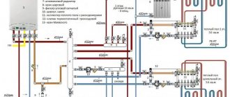
Below is a diagram where the two boilers indicated in the title are in one system with one radiator branch:
According to this scheme, two boilers in one system can operate both simultaneously together and separately.
In this case, I have already told you how to get hot water for hot water supply.
These same two boilers in one system with several radiator branches:
Please note: the wall-mounted boiler now has an expansion tank on the outside. This is because, most likely, the volume of its own built-in tank may not be enough
Due to the large flow of coolant through the thin tubes of a wall-mounted boiler, this scheme uses a hydraulic arrow and a manifold, which do not need to be purchased separately, but for ease and speed of installation, use the following:
For DHW, a double-circuit boiler will be used in the same way as in the example with one radiator branch. However, an indirect heating boiler can be easily added to this multi-circuit system by connecting it to the pipes of the same collector.
By the way, instead of one or more radiator circuits, you can connect a water heated floor.
Advantages and disadvantages
The advantages of dual-circuit systems include the following:
- Fuel efficiency. Since the competitor of a double-circuit boiler is usually the “single-circuit boiler + BCS” combination, the consumption of natural gas will be higher in the second case.
- Compact sizes. If we consider that the lion's share of double-circuit boilers are used in wall-mounted versions, it turns out that such systems can be located not only in the utility rooms of private houses, but also in ordinary kitchens of small apartments, where they can take up no more space than a kitchen cabinet.
- Ready solution. In the case of a double-circuit boiler, there is no need to purchase additional equipment and think about its compatibility. A heater, instantaneous water heater and circulation pump are already combined in one device. And all this is automated!
However, there are no ideal boilers; there are also disadvantages:
- Impossibility of simultaneous operation of two circuits. When hot water is turned on, the heating system is blocked by a valve. Therefore, high consumption of hot water can lead to a drop in room temperature.
- Wall-mounted boilers, especially compact ones with a small burner, cannot always heat water to the required temperature while maintaining strong pressure. The temperature at different water intake points may differ - the further the tap is from the boiler, the colder the water will be when opened at all points simultaneously.
- The secondary plate circuit is quite sensitive to the quality of running water. This requires either regular cleaning with chemicals or installing a special softener for hard water.
The issue of cost is deliberately considered separately, since it is both a minus and a plus. The cost of any double-circuit boiler will always be higher than that of a single-circuit boiler. But if you compare it with a boiler to which an indirect heating boiler is connected, then a double-circuit boiler will be cheaper.
Types of boilers
Types of boiler equipment:
gas. Highly effective, but not worth making at home. The units are classified as high-risk devices. Creation requires skills, technology;
A gas boiler
- electric boilers. Unpretentious in terms of creation and operation. You can make a heating device yourself. There are no increased security requirements;
- liquid fuel The design is simple. Any man can handle the job. Difficulty in adjusting the nozzles;
- solid fuel. Effective and versatile. Easy to use and manufacture. Easily modified and converted to other fuels. The units are also used for heating industrial areas.
Heat-resistant stainless steel has good technical parameters. But she's expensive. Equipment is required to process the material. You can choose cast iron.
When making it yourself, it is better to take sheet steel or a pipe with a thickness of at least 4 mm. The properties of cast iron are good. Simple, easy to process. Regular household devices can handle it.
Single-pipe connection diagram with boiler
Connection diagram for a gas single-circuit boiler.
The connection diagram for a gas boiler can be flow-through or circulation. In the first case, the coolant flows by gravity, leaving the heating boiler. In the second case, a special pump is used, which ensures forced movement of the coolant. This ensures fast and even heating.
In the first case, a single-pipe connection diagram is used, an example can be seen in Fig. 2. This is a serial connection, which has one drawback. If the temperature drops in one part of the system, it automatically begins to decrease in the rest. This scheme allows the coolant to circulate through the circuit independently, that is, pumps are no longer required. This makes installation a little cheaper, but bottling occurs from a boiler with a higher pressure than is possible with a two-pipe system.
Gas boiler connection diagram.
Often the single-pipe scheme with a boiler is also called the Leningrad one; it is recommended to use steel pipes for it, although today they are quite successfully replaced with plastic ones. Radiators should be steel or cast iron, this ensures that there is no large heat loss. Aluminum ones are almost never used, since heat loss during coolant movement will be significant. This is especially clearly visible in a two-story house. If aluminum radiators are used, then when water rises from the first to the second floor, it quickly cools, that is, the quality of heat is no longer what is required. Many people recommend installing two boilers, one for each floor or wing of a large building, but it is better to consider having a different heating scheme. It will be much cheaper.
In a single-pipe system, water is supplied to the radiators from the bottom up, but as it passes in a circle, it cools down greatly, so the last links in this chain receive very little heat. The coolant returns to the boiler already cooled.
Installation of a heating system with a heat accumulator
The use of such an element in a scheme with two boilers in one heating system has several features depending on the installed units:
- The heat accumulator, gas boiler and heating devices form a single closed system.
- Solid fuel boilers operating on wood, pellets or coal heat water, the thermal energy is transferred to a heat accumulator. This, in turn, heats the coolant circulating through a closed heating circuit.
To independently create a heating scheme with two boilers, you must purchase the following:
- Boiler.
- Thermal accumulator.
- Expansion tank of appropriate volume.
- Hose for additional coolant removal.
- There are 13 shut-off valves.
- Pump for forced circulation of coolant in the amount of 2 pieces.
- Three-way valve.
- Water filter.
- Steel or polypropylene pipes.
Such a scheme is characterized by operation in several modes:
- Transfer of thermal energy from a solid fuel boiler through a heat accumulator.
- Heating water with a solid fuel boiler without using this device.
- Receiving heat from a gas boiler connected to a gas cylinder.
- Connecting two boilers at the same time.
Price
The market for double-circuit gas boilers is very vast, however, it also has its key players, whose products are well known and trusted.
The Ferroli trademark is widely used among Italian manufacturers. The Fortuna Pro model, which has average characteristics, costs in Russia from 23 to 30 thousand rubles, depending on the capacity and distributor in the region.
German Vaillant boilers are deservedly popular among consumers
German quality is promised by factories such as Vaillant and Viessman. The 24 kW Vaillant TurboFit model will cost 40–45 thousand rubles, the Viessman Vitopend is slightly cheaper - about 35 thousand rubles with the same power.
No less popular are the products of the Slovak company Protherm. The price for a 24-kilowatt Jaguar fluctuates around 30 thousand rubles.
The huge variety on the boiler equipment market forces you to carefully approach your choice. After drawing up the project and determining the power parameters, proceed to choosing a model
Pay attention not to loud statements, but to the actual characteristics - heat exchanger material, circulation pump power, presence of forced draft from the combustion chamber. Electronic hardware can only be checked by operation, so demand transparency of warranty obligations
Make a balanced choice and let your home be warm.
Connecting an electric heating boiler: an important step
Features of connecting an electric boiler
On the one hand, installing a heating boiler cannot be called a very difficult job, and on the other hand, arranging a home heating system requires compliance with a certain technology for installing an electric boiler. The advantages of the electric boiler shown in the photo over other types of heating devices are that it can be installed at any point in the heating system, and it will function well, but only if the heating device is wired correctly, according to the connection diagram for the electric heating boiler.
Regardless of the heat supply circuit with an electric boiler, it must certainly have a grounding connection for the device. The device can be connected to an electrical panel, but the zero phase is prohibited. This is not just dangerous: the equipment perceives such actions as a short circuit.
Correct connection of the electric boiler to the network is one of the conditions for reliable operation of the heating system. It is also necessary to select high-quality components, and in addition to this, you need a professionally executed piping of the electric heating boiler. Properly done work will ensure a slight difference in the temperature of the coolant fluid at the inlet and outlet of the device. For this, the correct placement of the electric boiler and its subsequent connection is of great importance (read: “Connecting the electric boiler to the heating system: instructions”). Only if these rules are followed will the coolant be able to transfer heat to the radiators as efficiently as possible.
The need for piping an electric boiler
First of all, the electric boiler requires piping to protect the device from overheating. As practice shows, if the wiring diagram of an electric heating boiler is correctly executed, then heat loss is reduced, and, accordingly, money is saved. There is also no need to purchase expensive equipment to control the operation of the system.
If the model of an electric heating boiler is not initially equipped with an automatic unit that controls the functioning of the system, then correct piping is of great importance for the device. It will allow you to achieve maximum efficiency even when installing a not very powerful boiler.
Electric boiler wiring diagram
When executing the piping diagram, it should be taken into account that in addition to calculating the power for an electric heating device, it is necessary not to forget about its main purpose - to control the temperature difference of the liquid at the inlet of the device and its outlet.
- pipes of different diameters;
- heating radiators (read: “Tying heating radiators with polypropylene - simple and affordable”);
- circulation pump;
- pressure gauge;
- balancing valve;
- distribution valve;
- pass filter.
Equipment and tools should include a welding machine and wrenches.
As for additional and fastening products, the following will be needed:
- tees, adapters;
- safety, check, air valves;
- bolts, nuts, couplings.
The piping of an electric heating boiler is carried out according to one of four different principles:
- with forced water circulation;
- with natural coolant circulation;
- classic wiring option;
- using primary-secondary rings.
A room heating system with natural water circulation consists of:
The circuit providing forced circulation includes the following elements:
- room temperature regulator;
- radiators;
- electric boiler;
- open type expansion tank;
- safety unit consisting of a safety valve and pressure gauge;
- tap for replenishing the amount of coolant;
- pump;
- check valve;
- anti-condensation pump;
- minimum temperature sensor.
If the heating structure operates using a wall-mounted electric heating device, then all its elements are also included in the piping, which, in addition to heat supply, can provide hot water supply and the functioning of the “warm floor” heating system.
Emergency piping of an electric boiler
The piping of an electric heating boiler with a double-circuit circuit must necessarily provide methods for monitoring and managing the system if an unforeseen emergency occurs. For example, the power supply may go out. Sometimes the problem with a temporary lack of electricity can be solved by using uninterruptible power supplies or batteries (they should be charged periodically if necessary).
Features of electric heating equipment
There is a widespread belief that all types of electric heaters provide savings of about 30-40%, and installation of an electric heating boiler will be as profitable as possible. The values described are large, and in theory they allow you to save a significant amount on heating. As a rule, the reason for such efficiency is given as reduced power - i.e. When calculating a heating system, you need to assume that heating one square meter of room requires about 60 W of energy instead of the required 100 W.
Everything said in the previous paragraph is the erroneous opinion of most users. It is not advisable to compare direct heating devices in terms of efficiency, since they will all be equal. This statement is based on the law of conservation of energy, according to which energy cannot appear out of the blue and disappear into nowhere.
In relation to electric heating devices, this means that all generated energy will be converted into heat. Of course, this phenomenon will be accompanied by certain losses - nevertheless, part of the heat will certainly dissipate in the air and will not be transferred to the coolant. But the volume of losses directly depends on the insulation of the device body, and not on the type of heating equipment. In addition, the heat released outside will directly warm the room where the boiler is installed.
If we look at the problem from the other side, then heating is designed to compensate for heat losses, the amount of which is determined by:
- The quality of building insulation, which is completely independent of the efficiency of the heating boiler;
- The difference in temperature in the house and outside, which also does not depend in any way on the heating equipment used.
To summarize, we can definitely say that the type of heat source has no relationship with the thermal power required to heat the building - which means that the vaunted efficiency of electrical devices is simply absent.
However, this only applies to efficiency - each electrical device has special performance qualities:
- Electric radiators. Such devices load the electrical network evenly, so there are no wiring requirements.
- Induction boilers. Such heating equipment is compact and reliable. The latter quality is due to the fact that there is no heating element in the heat exchanger, and the power controller and coil are located outside, so water does not have any effect on them. In addition, induction boilers can work with any coolant.
- Electrode boilers. Differ in smallest sizes. Such boilers require constant replacement of electrodes, since they dissolve in water over time. Only water containing a certain amount of salts can be used as a coolant.
- Heating element boilers. The main problem of boilers with heating elements is the constant deposition of scale on the heating elements (this factor is irrelevant for closed heating circuits, in which the amount of salts is initially limited). In addition, these devices are quite large in size.
How to make heating with two boilers
Creating a circuit for two heating boilers is associated with the obvious decision to make maximum use of the functionality of diverse types of heating systems for a private home. Today, several connection options are offered:
- gas boiler and electric;
- boiler for solid fuel and electricity;
- solid fuel boiler and gas.
Before you begin selecting and installing a new heating system, we recommend that you familiarize yourself with the brief characteristics of the operation of combined boilers.
Connecting electric and gas boilers
One of the easiest heating systems to operate involves combining a gas boiler with an electric one. There are two connection options: parallel and serial, but parallel is considered preferable, since it is possible to repair one of the boilers, replace and shut down, and also leave only one operating in minimum mode.
Such a connection can be completely closed, and ordinary water or ethylene glycol for heating systems can be used as a coolant.
Connecting gas and solid fuel boilers
The most technically complex option, as it requires careful preparation of the ventilation system and premises for large and fire-hazardous installations. Before installation, read the installation rules separately for gas and solid fuel boilers, choosing the best option. In addition, the heating of the coolant is difficult to control in a solid fuel boiler, and to compensate for overheating, an open system is required, in which excess pressure is reduced in the expansion tank.
Important: a closed system when connecting gas and solid fuel boilers is prohibited and is considered a serious violation of fire safety. Optimal performance of two boilers can be achieved using a multi-circuit heating system, which consists of two circuits independent of each other. Optimal performance of two boilers can be achieved using a multi-circuit heating system, which consists of two circuits independent of each other
Optimal performance of two boilers can be achieved using a multi-circuit heating system, which consists of two circuits independent of each other.
Connecting a solid fuel and electric boiler
Before connecting, evaluate the technical characteristics of the selected electric boiler and read the instructions. Manufacturers produce models for open and closed heating systems. In the first case, the best option is to focus the operation of two boilers on a common heat exchanger; in the second, it can be easily connected to an already operating open circuit.
What kind of heating is there?
Basically, heating systems are usually classified according to the method of coolant circulation:
- Gravity (with natural circulation). The movement of heated water through the pipes here occurs due to natural convection. Masses with a higher temperature gradually rise to the top, being forced out by colder and denser layers of water. Further, as it cools, the coolant again falls down under the influence of gravity. Such systems are completely energy independent. In this case, connecting the gas boiler to electricity is not required.
- Forced. It is assumed that pumping equipment will be used to circulate the coolant. This allows you to significantly increase the speed and uniformity of heating of the heating system. The boiler must be connected to the electrical network in accordance with all standards and regulations.
Electrical connection
The power supply circuits are the same for all electric boilers, the only difference is the number of phases. Devices with a power of up to 12 kW are connected to a single-phase 220 V network, more than 12 kW - to a three-phase (380 V). What you will need for installation:
- power cable with copper conductors;
- differential circuit breaker or combination of RCD + conventional circuit breaker;
- ground loop.
A VVG cable of any type is used as a power line; the number of cores depends on the number of phases - 3 or 5. Select the cross-section of the current-carrying part according to the power of the heat generator, usually this parameter is indicated in the product’s operating instructions. To simplify the task, we present the data for different boilers in the form of a table.
The rating of the differential circuit breaker also depends on the power consumption of the heater; the operating current is 30 mA. For example, to protect the power line of a 3 kW (220 volt) unit, you will need a device rated at 16 A; for a power of 16 kW (380 V), you need a 32 A difavtomat. The exact ratings are indicated in the product data sheet.
To independently connect a wall-mounted electric mini-boiler room, you need to remove the front panel, run the power cable inside and connect the wires of the corresponding colors to the terminal block contacts. As a rule, the neutral wire is indicated in blue, grounding in yellow-green. The control box of the induction and electrode boiler is connected in the same way.
Electrical connections between the control cabinet and the heating block of an electrode or induction boiler are made according to the individual diagram presented in the instructions. As an example, we give a connection diagram for the popular Galan electric boiler.
Automation diagram for single-phase 220 V networkThe temperature of the coolant here is monitored by overhead sensors installed on the metal sections of the supply and return pipelines. The devices are connected in series with the contacts of the thermal relay that controls the magnetic starter. When the upper temperature threshold is reached, the circuit breaks and the starter turns off the heating.
Connection diagram for connecting the boiler to a three-phase 380 V network
Equipment installation rules
Installation and connection of the boiler to the system should begin after passing the design stage, when a place in the house has been prepared for the unit. If you install it in violation of the requirements, the specialists of the gas distribution company will not connect the equipment to the gas main.
General requirements at the design stage
The basic standards for installing gas equipment are prescribed in SNiP 42-01-2002. Supporting information is also contained in the already invalid, but useful SNiP 2.04.08-87.
Usually all the rules are taken into account by the design engineer, but it is also useful to know them for yourself. The room for the boiler can be a kitchen if the power of the device ranges up to 60 kW. A separate or attached combustion chamber is relevant for units with a power rating of up to 150 kW.
Additional standards for the installation of gas equipment are given in SNiP on boiler installations, as well as on heating, ventilation, and air conditioning
The premises requirements are as follows:
- The minimum room height is 2 m, volume is 7.5 m3. If there are two or more gas appliances, the parameters change to 2.5 m3 and 13.5 m3, respectively.
- Not suitable for installation: basements, balconies, bathrooms, corridors, rooms without windows.
- The walls of the room must be covered with non-flammable materials or protected with special panels.
- Lighting: per 10 m3 of room there is at least 0.3 m2 of window. In the event of a gas explosion, the windows are an easily removable structure, which increases the safety of equipment operation.
- It is necessary to have grounding and a cold water pipeline.
- The cross-section of the chimney corresponds to the power of the installed equipment.
- The space left around the device is: in front - from 1.25 m, on the sides (if maintenance is necessary) - from 0.7 m.
- The distance from the vertical chimney to the unit is maintained - no more than 3 m.
Ventilation must also be provided. Natural is calculated at the rate of 3 room volumes per hour. When organizing a supply air system, combustion air is added to this value (the parameter is indicated in the boiler passport).
The requirements apply not only to premises. The distance from the attachment to the nearest structures is also regulated. This information is indicated by the manufacturer in the equipment instructions.
If a double-circuit boiler is installed on a wooden wall, a sheet of roofing steel (0.8 - 1 mm) or a mineralite slab is attached to it. If the equipment is not located in the kitchen, asbestos is also possible
Floor-standing boiler models are installed on non-combustible bases. If the surface is wooden, a metal backing is required.
It is recommended to place the device as close to the gas pipe as possible. The use of special hoses is acceptable, but they should not be very long. Bellows hoses up to 5 m are available on sale; they are allowed for installation, but according to European standards, the length is limited to two meters.
Documentation preparation process
After a general familiarization with how to technically correctly connect double-circuit gas boilers, you can begin preparing documentation. The first stage is obtaining technical specifications. It is necessary to contact the regional gas service with a statement indicating the expected volume of blue fuel consumption per hour.
Technical specifications are issued in 1-2 weeks. The document is a permit to connect housing to the gas main.
The second stage - according to the technical specifications, an equipment installation project is developed. The third is approval of the prepared documentation by engineers of the gas distribution company.
The project includes both the installation diagram of the boiler itself and the laying of a gas pipeline from the connection point to the main line. If we are talking about a private house, a drawing of communications on the site is added
The boiler technical passport, operating instructions, certificates, and an expert opinion on the compliance of the device with all standards are submitted to the regulatory organization. The necessary papers are provided by the manufacturer of the double-circuit boiler.
Coordination of documentation can happen in a week or last up to 3 months, it all depends on the complexity of the project. In case of refusal, the inspection is obliged to provide a list of edits to eliminate the deficiencies. If all requirements are met, stamps are affixed and you can begin connecting the equipment.
Closed system with heat accumulator
A closed heating system does not require the installation of an expansion tank, so the installation process is greatly simplified. Most often, gas boilers are equipped with an expansion tank and a safety valve.
To properly assemble such a heating circuit, you must follow certain instructions:
- A tap and a pipe leading to the heating devices are connected to the supply fitting of the gas boiler.
- A pump is installed on this pipe for forced circulation of the coolant. It should be placed in front of the radiators.
- Each radiator is connected in series.
- A pipe goes from them to the heating boiler. At the end of the pipe, at a short distance from the unit powered by a gas cylinder, a shut-off valve is installed.
- The supply and return pipes are connected to the pipes going to the heat accumulator. One of the tubes is connected in front of the pump, the second tube is connected behind the heating devices. Each tube is equipped with a tap; the tubes that were previously cut in before and after the heat accumulator should also be connected here.
Why do you need a heat accumulator?
The heat accumulator is a tank that is connected to the boiler and water circuit. Its body is reliably covered with a heat insulator and allows it to accumulate warm water for the circuit, and then heat the room for about a day when the boiler is turned off.
How does a heat accumulator work:
- The heating unit is loaded with fuel and ignited.
- The circulation pump pumps coolant through the heat exchanger. Cold water from the bottom of the tank rushes into the boiler, and already heated water arrives at the top. Since the density of the cold and hot liquid is different, it will not mix. This will gradually fill the tank with hot water.
- If the calculations are done correctly, when the fuel burns out, the container will be filled with hot water at the required temperature. Good thermal insulation will keep the coolant hot for a long time.
- When the boiler is not functioning, the heating system continues to perform its task. The circulation pump of the heating circuit circulates the coolant through the system. Water is drawn from the top “hot zone” of the tank.
- The water returns to the return line already cooled, so the heat accumulator will gradually release the accumulated heat.
In real conditions, water is drawn into the heating system continuously. The heat accumulator accumulates “excess”, currently unclaimed heat.
A battery with a volume of 3 tons, with a supply of water at a temperature of 40-80°C, will be able to heat a house with an area of 80 sq.m. for a day. These parameters correspond to 170-175 kW hour. heat.
A regular boiler needs to be heated up to five times a day. If a heat accumulator is installed, the frequency of adding fuel to the combustion chamber will be reduced by five times. The heated water in the tank will gradually release heat energy to the radiators. A solid fuel boiler will work much more economically. This scheme for connecting a heating boiler in a private house allows you to heat the room for a long time without reducing the boiler power.
It is very beneficial to pair a heat accumulator with an electric boiler when saving energy resources is especially important.
On a note. The night tariff with a two-tariff meter is much lower than the day tariff: 2-4 times. If you turn on the electric boiler only at night, so that during the day the heat accumulator only gives off heat, you can significantly save on electricity.
Installation with electric or gas unit
Two heat generators can be installed in one heating system, the main one is a solid fuel unit, and the additional one is a boiler running on gas or electricity. This option is convenient because at night you can turn on the boiler, which operates in automatic mode. Gas in cylinders is inconvenient to use as the main energy carrier due to the need to take care of regular fuel supplies. Electricity is the most expensive energy source and it is most profitable to operate such a boiler unit only at night if the region has a system of cheap night tariffs.
How to connect solid fuel and gas boilers into one heating system for a large house? The simplest option is to connect two heat generators in parallel through a heat accumulator, which will additionally serve as a hydraulic separator.
The gas boiler operates in standby mode while the water in the buffer tank is heated by the solid fuel unit. After the fuel burns out, the coolant begins to cool, and as soon as the temperature sensor transmits the corresponding signal to the gas unit controller, it automatically turns on. When a solid fuel heat generator is restarted, the reverse process occurs - heating the coolant above a certain temperature leads to the gas burner turning off.
A system with an electric boiler in large houses is installed according to a similar principle. But for small private houses, a simpler and cheaper option for connecting a TT and an electric boiler is relevant (see diagram).
Connection diagram for solid fuel boiler and electric boiler
Boiler units are connected in parallel with the installation of check valves at each outlet. The electric boiler is equipped with a built-in circulation pump, which cannot be turned off, so for a solid fuel heat generator it is necessary to select a more powerful pump so that the TT boiler has an advantage over the electric one when operating together.
- a thermostat that turns off the boiler’s TT circulation pump when the coolant cools down;
- a room temperature sensor, which turns on the electric boiler when the room temperature drops after the fuel burns out in the TT unit.
Method of primary and secondary rings
How to connect two boilers into one system using a minimum amount of electronics? The use of the method of primary and secondary circulation rings allows for joint piping of the CT of the unit and the electric boiler. Hydraulic separation of flows is carried out without installing a hydraulic arrow.
Option for connecting two types of boilers to one heating system
Both boilers, the DHW boiler, as well as all heating circuits, are connected by both supply and return pipelines to a single circulation ring - they are the primary one. The minimum pressure drop is ensured by the small distance between each pair of connections (no more than 300 mm). The pressure of the pump installed on the main circuit ensures the movement of the coolant along the primary ring, while the flow intensity is not affected by the pumps of the secondary circuits (to which heat consumers are connected).
For the system to function properly, it is necessary to perform complex hydraulic calculations and select the optimal pipeline diameter for all circuits
It is also important to calculate the pump performance. The actual performance of the pumping unit on the main circuit must exceed the coolant flow rate on the most “volumetric” secondary circuit
Both boilers are equipped with shut-off thermostats so that they can operate instead of each other.
Standards for the distance between the boiler room and a multi-storey building
The construction of boiler houses for multi-storey buildings is regulated by Sanitary Standards and Rules:
- Built-in boiler rooms cannot be installed in multi-storey buildings.
- It is allowed to install heating equipment in basements, basements, and on the roof of a residential building, if the thermal power does not exceed 3.0 MW.
- Rooftops are equipped with sound and light fire alarms. They are installed only on the technical floor. Location directly above apartments is prohibited. The floors in the boiler room are insulated with reinforced concrete slabs.
- Attached buildings cannot be placed on the entrance side. The minimum distance to windows is 4 meters horizontally, 8 meters vertically.
Boiler houses with higher power for microdistricts should be located in separate buildings. Sanitary zones must be observed:
- for industrial gas boiler houses belonging to hazard class 3 - at least 300 meters;
- for solid fuel boiler houses, the size is calculated individually.
Boiler room of a multi-storey building with a solid fuel boiler
The calculations take into account noise and the level of air pollution from emitted combustion products.
SUMMARY
Every connection scheme, whether parallel or serial, has a right to exist.
The question is - how can you effectively and competently organize the linking of boilers for working in pairs in parallel or in series!?
The answer is that in each individual case, a different connection method will be appropriate. And the main factors that will influence the choice of boiler connection type are:
- The ratio of thermal and energy parameters: (20
40) L /1 kW (the ratio of the total volume of system coolant per 1 kW of boiler power);
- Physical possibility of implementing one or another project;
- Financial capabilities to implement option 1 or 2.
Here you will learn:
Nothing prevents you from assembling the heating system yourself, but this requires certain knowledge. It is not enough to hang a heating boiler on the wall - you need to connect batteries to it. Installation of the harness will also be required. It will help make your heating system more efficient, safe and balanced. The heating boiler piping diagram includes many elements. Let's find out what these elements are and what they are needed for.
Multi-fuel boilers instead of two boilers
For small heat supply facilities, it is possible to install boilers whose design allows for the simultaneous combustion of several types of fuel.
The best pairs have proven themselves:
- solid fuel - electricity;
- main gas - liquefied gas;
- main gas - fuel oil;
- liquid fuel - electricity;
- liquefied gas - electricity;
The first pair is the most common and is implemented in many domestic solid fuel boilers, when heating elements with a load of at least 50% of the rated power are installed in the heating circuit.
Thus, having decided to equip a boiler room with two boilers capable of working together, the user definitely wins by receiving a more modern energy-efficient combined heat supply scheme.
With the correct selection of equipment, you can achieve not only the minimum cost of thermal energy, but also increase the level of automation, reliability and safety of the heating source.
Scheme with an additional heat exchanger
This boiler connection scheme is in demand when there is a need to completely waterproof individual circuits of the heating system. This need arises when using various coolants in circuits. That is, water can move in one, and antifreeze in the other.
The harness shown in various photos looks like this:
- Boiler.
- Heat exchanger.
- Various heating circuits.
- Safety elements installed on each circuit, a circulation pump, a drain valve and a make-up valve.
The heat exchanger is a heat accumulator with at least three coils. One circulates water heated in the boiler, and the other two circulate various types of coolants. Heat from the first coil is transferred to the others through the water in which they are located.
The benefit of an additional heat exchanger also lies in the ability to combine open and closed systems. The first is safer for the operation of the boiler, the second is more gentle for radiators.
Security group
Tying a heating boiler with polypropylene will require the mandatory use of a circulation pump so that it can push the coolant through thin pipes. In this case, it is recommended to build a closed-type system with a sealed expansion tank. To operate such a circuit, you will need a safety group that includes three devices:
- Pressure gauge or thermomanometer;
- Automatic air bleeder;
- Safety valve.
Let's consider the purpose of these devices.
A pressure gauge is a device that measures pressure in closed systems. Such control is necessary due to the fact that the coolant does not have an outlet to the outside, as is implemented in open circuits. The standard pressure in heating private houses is up to three atmospheres. When the coolant overheats, the pressure rises, threatening to damage the installed equipment. And the pressure gauge allows you to assess the situation and take action.
Automatic air vents are installed not only in security groups - they are mounted next to heating radiators and in the distribution manifolds of heated floors.
There are many reasons why heating can become airy - oxygen dissolved in water, the reaction of water with metal, air penetration through small cracks or through plastic pipes. Previously, this problem was solved with the help of taps embedded directly into the heating radiators. Today, automatic air vents are responsible for this. They are present as part of safety teams and independently release air from the pipes without requiring human intervention.
The safety valve is an important link in the piping circuit of a floor-standing or wall-mounted boiler operating in a closed heating system. It is triggered when the pressure is exceeded, releasing the accumulation of air and coolant, preventing an emergency from occurring. It is simply impossible to do without this link in modern heating.
Rules for installation on a wall or floor
The gas unit must be placed inside a separate room. which meets the following requirements:
- There is a window that can be opened at any time.
- Availability of functioning ventilation.
- Availability of gas and water pipes.
- The presence of an outlet to ensure the operation of the circulation pump and electronics. Of course, it should be the end of a separate branch that extends from the electrical panel. This cable must be connected to a separate circuit breaker. In addition, grounding is mandatory.
There are also requirements regarding the correct placement of the boiler in the house. They are:
- The distance between the main element of the heating system and other gas appliances must exceed 20 cm.
- There should be no window nearby.
- The distance between the boiler and the socket should be at least 0.5 m (at least, such recommendations are given by manufacturers). In general, the further the outlet is from the boiler, the better. It is worth adding that some models have a power cable without a plug. This means that you need to connect the wire yourself directly to the circuit breaker located in the electrical panel.
- The space between the side walls of the boiler and adjacent walls or objects must be greater than 15 cm.
- The wall on which or near which the boiler is installed must be strong and covered with non-flammable substances. If the wall is such that it can catch fire, it should be covered with at least 3 mm of non-combustible material. This is often noted in various videos.