Information on the purpose of the calculator
The online water heated floor calculator is designed to calculate the main thermal and hydraulic parameters of the system, calculating the diameter and length of the pipe. The calculator makes it possible to calculate a heated floor, implemented using the “wet” method with the arrangement of a monolithic floor made of cement-sand mortar or concrete, as well as with implementation using the “dry” method, using heat-distributing plates. The installation of the TP system using the “dry” method is preferable for wooden floors and ceilings.
Heat flows directed from bottom to top are the most preferable and comfortable for human perception. That is why heating rooms with heated floors is becoming the most popular solution compared to wall-mounted heat sources. The heating elements of such a system do not take up additional space, unlike wall-mounted radiators.
Properly designed and implemented underfloor heating systems are a modern and comfortable source of space heating. The use of modern and high-quality materials, as well as correct calculations, allows you to create an effective and reliable heating system with a service life of at least 50 years.
A heated floor system can act as the only source of room heating only in regions with a warm climate and using energy-efficient materials. If the heat flow is insufficient, it is necessary to use additional heat sources.
The calculations obtained will be especially useful for those who plan to implement a heated floor heating system with their own hands in a private home.
General information on the calculation results
- Total heat flow - The amount of heat released into the room. If the heat flow is less than the heat loss of the room, additional heat sources are needed, for example, wall radiators.
- Heat flow in the upward direction - The amount of heat released into the room from 1 square meter of area in the upward direction.
- Heat flow in the downward direction - The amount of heat that is “lost” and not involved in heating the room. To reduce this parameter, it is necessary to select the most effective thermal insulation under the TP* (*warm floor) pipes.
- C total specific heat flow - The total amount of heat generated by the heating system system from 1 square meter.
- Total heat flow per linear meter - The total amount of heat generated by the TP system from 1 linear meter of pipe.
- C average coolant temperature - The average value between the calculated coolant temperature of the supply pipeline and the calculated coolant temperature of the return pipeline.
- Maximum floor temperature – The maximum temperature of the floor surface along the axis of the heating element.
- M minimum floor temperature – Minimum temperature of the floor surface along the axis between the TP pipes.
- Average floor temperature – Too high a value of this parameter can be uncomfortable for a person (standardized by SP 60.13330.2012). To reduce this parameter, it is necessary to increase the pipe pitch, reduce the temperature of the coolant, or increase the thickness of the layers above the pipes.
- Pipe length – The total length of the TP pipe, taking into account the length of the supply line. With a high value of this parameter, the calculator will calculate the optimal number of loops and their length.
- Thermal load on the pipe - The total amount of thermal energy received from thermal energy sources, equal to the sum of the heat consumption of thermal energy receivers and losses in heating networks per unit time.
- Coolant consumption - Mass quantity of coolant intended to supply the required amount of heat to the room per unit of time.
- With the speed of movement of the coolant - The higher the speed of movement of the coolant, the higher the hydraulic resistance of the pipeline, as well as the level of noise created by the coolant. Recommended value is from 0.15 to 1m/s. This parameter can be reduced by increasing the internal diameter of the pipe.
- Linear pressure loss - A reduction in pressure along the length of a pipeline caused by the viscosity of the liquid and the roughness of the internal walls of the pipe. Without taking into account local pressure losses. The value should not exceed 20000Pa. Can be reduced by increasing the internal diameter of the pipe.
- About the total volume of coolant - The total amount of liquid to fill the internal volume of the pipes of the TP system.
What is a water heated floor?
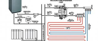
A warm water floor is a system of pipes hidden under a screed through which water of a certain temperature of about +45°C circulates. Today, this is the most popular technology for heating private homes. Thanks to the circulation of water inside the system, heating is uniform and comfortable, unlike radiator heat distributors. Simplicity of design, independence from seasonal heating, temperature and pressure fluctuations are another big advantage of this technology. This system is heated mainly using a gas boiler. But it also interacts with other types of boilers without any problems.
Warm floors are installed from polyethylene or metal-plastic pipes. These materials are quite flexible and conduct heat well. A pump, a manifold and a thermostatic mixer are responsible for regulating the temperature in such a system.
Advantages of water heated floors:
- compatibility with many types of flooring - you can choose any coating you need without worrying that the heating system will damage it;
- heat saving - the system produces heating from below, thanks to which all the cold air rises, which allows you to heat the room without using other heat sources;
- seasonal options - in the cold season, the system acts as a heating structure, and in the summer it is capable of cooling the room.
However, there are features that you need to be familiar with before installing such a system:
- More expensive than a radiator system . When installing a heated floor at home, prepare for increased expenses, which will not really pay for themselves, but at the same time will bring a lot of pleasant things in terms of heating.
- Doesn't handle warming up everywhere . In most cases, underfloor heating is used as the main heating, but there are rooms where an additional heating device is required. To clarify this fact, you need to calculate the heated floor.
- Prohibition for use in multi-apartment buildings . But it concerns mainly Russia. There are no restrictions in other countries.
This technology is more appropriate in a private house rather than an apartment. It is advisable to entrust the installation of the system to specialists, since there is a possibility of leaks that do not appear immediately. Poor assembly can cause a lot of trouble and cause serious damage to property.
Snail program for heated floors free download
Water heated floor project
Water heated floor project. Concrete system.
Professional design of underfloor heating systems (water heated floors) for buildings of various purposes and designs (cottage, shopping center, business center, service station, workshop, etc.), and any heat sources in accordance with European and Russian standards and norms.
The project is necessary for the installation of a water heated floor and is a passport of the system, incl. for subsequent system maintenance.
The project includes calculation of heat loss of a building taking into account the climate zone. The materials, thickness and design of walls, ceilings, insulation of the foundation and roof, filling of door and window openings, and floor plans are taken into account. When designing, all the features of the building and the individual wishes of the customers are taken into account. The completed underfloor heating system project includes the following main sections:
- results of thermal engineering calculations,
- system passport,
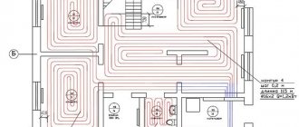
- installation diagrams for laying underfloor heating pipes, lines, damper tape, placement of thermostats,
- balancing tables for underfloor heating collectors,
- specification of materials and components.
In our projects, the layout of pipes is carried out by an experienced designer, and the pipes are laid in accordance with the Thermotech method in a “meander” (“snail”) and with variable pitch with the identification of edge (welt) zones. Unlike some companies working under the umbrella of famous brands, where the pipe layout is automatically performed by a “proprietary” computer program using a primitive “snake” with the same pitch. In warm Europe, the “snake” is used for buildings with very low heat losses (up to 30 W/m2); with increased heat losses, designers are forced to switch to the “snail” and use welt zones along the external walls to compensate for the increased heat losses. Programs don't do that yet.
Project of a water heated floor in a domed house
But, as a rule, in our climatic conditions, and with lagging standard requirements for the insulation of enclosing structures, as well as the widely practiced lack of external thermal insulation in individual construction, with heat loss, everything is much worse. It’s good if the heat loss of the house falls within the value of 75-80 W/m2 of floor, but more is also not uncommon, but rather the opposite in private buildings. But our specialists have been successfully designing and implementing underfloor heating systems in the harsh conditions of Siberia for a long time and have enormous experience in this area. This allows us to carry out projects that best suit our (and any) climatic conditions and the individual characteristics of a particular object.
Water heated floor project for a log house. Installation diagram. Concrete system.
To develop a water heated floor project, ideally you need a building project or at least floor plans, preferably in AutoCad format. In their absence, floor plans with all dimensions drawn by hand are needed. In addition, technical specifications for the design are drawn up and agreed upon.
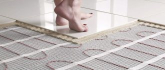
The design of the underfloor heating system is carried out taking into account the characteristics of the building and the wishes of the customer. For weak floors or thin systems, the project can use lightweight underfloor heating systems with aluminum heat distribution plates or a foil system.
Installation diagram of a warm water floor. Foil system.
The result of the design is a package of technical documentation containing a system passport with the results of thermal engineering calculations, installation diagrams for laying water-heated floor pipes and placement of room thermostats, collector balancing tables and specifications of materials, equipment and components.
The completed project allows us to fully equip the system with equipment, components and materials in accordance with the attached specifications and carry out installation and commissioning of a working system.
Tags: floor scheme, floor calculation, heated floor scheme, heated floor calculation, heated floor calculation, water floor scheme, water heated floor scheme, water floor calculation, heated floor water calculation, design of warm water floor
Make a request:
call: +7(383)2486390
MTS / WhatsApp / Viber: +79833216510
Open this link to write to WhatsApp: https://wa.me/79833216510
Send a message via any of the available instant messengers by clicking on the dialogue form in the lower left corner of the page
Use the online chat on the website in the lower right corner of the page
Calculation of heat loss at home
Before calculating a water heated floor, you must first calculate the heat loss of the house. Heat loss is the amount of heat that a room loses per unit of time. To reduce heat loss, heating devices are used, for example radiator heaters, heating pipes, and heated floors. In addition, it is possible to reduce heat loss by installing double-glazed windows and insulating walls with various materials that can retain heat inside the room.
Calculation of heat loss is an important parameter when designing a residential premises. In this case, it is necessary to take into account:
- room area;
- area of all windows;
- ceiling height;
- number of external walls;
- temperature from the outside of the room;
- window type;
- thermal insulation of walls;
- type of room located above.
Basically, heat loss depends on the difference in temperatures outside and inside the room, as well as on the degree of thermal insulation of windows, walls, and partitions. To more accurately calculate heat loss, you can use one of the many online calculators. They are quite simple and easy to use; just enter the required values and the calculation will be done automatically. In such calculators it is possible to calculate heat loss through windows, ceilings, walls, and floors. This will allow you to obtain detailed information on the basis of which the power of the heating equipment should be calculated.
It is generally accepted that a warm floor will cope if the heat loss does not exceed 100 W per meter of area. If this indicator is exceeded, you will have to resort to installing an additional heating device.
Simple layout
We save material - we save time - we get an accurate layout
. I used the program myself and, thanks to it, I performed all the calculations myself, purchased everything and was not disappointed - even in the demo version, I printed the results via a screenshot, wound everything up and everything works - I’m very pleased. Thank you.
From a conversation on an online forum
They ask us questions
Good afternoon Will the program continue to live? People on the forumhouse are worried. It was possible to draw all the loops, albeit approximated, but without studying any compasses, autocads, etc. I drew a 300 square meter 3-level house for myself, made the purchase, installed everything, I’m just delighted with the program
From a user letter
Builders are looking for
You need a simple program in which you can calculate the length of TP loops. I don't need heat loss calculations. You just need to decide how many loops to make and how much pipe to take. What is recommended on the Internet either does not download or does not run for me. A huge request, send me an email or give me a link to the working program!
In many apartments today, water-heated floors are installed for reasons of economy. The heating supply temperature in these systems is much lower than when using radiators. Before you design and plan a heating system, it is necessary to determine the heat energy requirements, power and load to heat each room in the building. To calculate a water heated floor according to the program, you need to decide on the parameters of the future coating.
Detailed calculation of water heated floor
When making calculations, please note that the maximum optimal floor surface temperature will be 28 degrees. If this value is exceeded, discomfort may occur. In places where the floor borders windows or doors and external walls, the temperature can be higher up to +35°C, and in bathrooms up to +33°C.
Also pay attention to the coating you are going to use, since each coating has its own heat transfer resistance. The recommended value should not exceed 0.15 M2K/W
When calculating a water heated floor, please note that the maximum coolant temperature should not exceed 55 degrees. The optimal loop loss is usually 10 degrees. That is, if your supply is 50 degrees, then the return will be around 40 degrees
The heat flux density per 1 m2 is calculated as follows:
Using the obtained value of the heat flux density (q), the room temperature and the temperature on the floor surface, we calculate the required difference in temperature of the coolant and the pitch of the pipe, using the appropriate table (attached in the example). Next, using the formulas G=3.6*Q/4.187*(tz-tp) and L=F/b, we calculate the required water flow through the floor heating system and the length of the pipe being laid, where:
TOP 6 professional programs
Such software is suitable for builders, engineers, pipe laying and other communications specialists.
HERZ CO
This is the main graphic editor for creating designs for hydraulic equipment and two-pipe heating and cooling systems.
you can from the official website.
Advantages and disadvantages
selection of pipeline diameters;
water flow analysis;
water flow analysis;
selection of settings for the regulator of intermediate pressure indicators;
calculation of the required authorities of thermostatic valves;
preliminary assessment of configured valves that reduce excess pressure;
displaying data in graphical form;
entering information on objects into tables created in the Hertz assistant;
reflection of entered values in the help system;
automatic identification of areas with a connected pipeline, heating devices, fittings, indicating the area of the room.
Herz is only suitable for creating heating schemes without taking into account other room parameters.
RAUCAD/Rauwin 7.0
Provides modular design through a single database.
and you can get acquainted with the training material on the official website.
Availability of the Rauwin tabular module, created for thermotechnical calculation of external fences, flooring and thermal power of the heating system, selection of a heating device of the Rehau brand.
Advantages and disadvantages
arbitrary calculation of the internal heating system with water supply and drainage;
works on AutoCAD® with the basic graphical symbol GOST;
wide functionality: project management, drawing up orders for commercial proposals;
a clear interface for creating models of pipeline heating networks in 2D and 3D;
generating diagrams, making drawings using tables and providing graphical data;
calculation of water supply projects;
distribution of eliminations in a stagnant zone, dangerous from the point of view of a possible increase in the number of bacteria.
it will be difficult for beginners to understand the requirements and settings;
the software is not suitable for older models of PCs and laptops;
The program is adapted only for Rehau products.
Video: how to calculate a warm water floor in the RAUCAD/Rauwin 7.0 program.
Example of heated floor calculations
By calculating heat loss, we found out that in a particular room they amount to 1200 W. We also know that we want the room temperature to be 20 degrees. The useful area of the heated floor is 20 square meters. There will be parquet on the floor. The thermal resistance of parquet is 0.1 m2K/W.
First, let's determine the heat flux density per square area.
The calculation table shows that we can achieve the desired temperature of 20 degrees with a laying step of 25 cm. In this case, the temperature of the floor surface will be 25.3 degrees.
You can find more tables, as an option, in the book “Metal-polymer pipes and fittings” from the Egoplast company.
It is not difficult to determine the length of the pipe
We find the water consumption using the formula G=3.6*Q/4.187*(tz-tp). The temperature according to the table is 50/40.
This data will help when setting values on the distribution manifold flow meters.
For our conditions, we need to lay out 80 meters of pipe in 25 cm increments. This is the ideal length of the circuit. If the value exceeds 90-100 meters, it is advisable to divide the room into two circuits.