- Catalog
- Water heated floor
Mixing units and valves (equipment for the preparation and circulation of underfloor heating fluid)
Manifold blocks (modules of distribution and control valves)
Pipes for water heated floors (pipes for built-in heating systems)
Automation for controlling water heated floors (control and regulation devices)
Accessories for water heated floors (additional fittings, fittings and instrumentation)
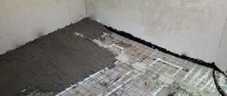
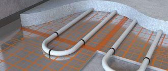
Construction materials for water heated floors (materials for “wet” and “dry” installation of heated floors)
Manifold cabinets (distribution cabinets)
Standard kits for installing heated floors (technical specifications)
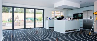
Water heated floor - comfort and efficiency
Modern standards and requirements for buildings are aimed at reducing heat loss and increasing the energy efficiency of heating systems. This is a prerequisite for the further development and implementation of built-in heating systems, primarily water heated floors (underfloor heating).
Thanks to energy efficiency and the ability to create the most comfortable temperature conditions for a person in rooms, water-heated floors have firmly entered the arsenal of engineering equipment in a residential building. Currently, heating based on water-heated floors is provided in many residential buildings under construction and reconstruction.
Water heated floor VALTEC
The VALTEC brand was one of those who had a serious influence on the popularization and development of built-in heating systems in Russia and other neighboring countries. In our range you will find everything you need to create the most comfortable and reliable underfloor or combined heating system.
- Thoughtful, practice-tested technical solutions.
- Quickly complete the project with products of one brand.
- Optimal cost.
- The choice of equipment depends on the customer’s requests and budget.
- Easy installation and operation.
- Comprehensive technical support.
Advantages of VALTEC underfloor heating:
Setting up manifolds with tuning flow meters
Preliminary adjustment of underfloor heating collectors is necessary and important. Even if the system has thermostats, controllers and other automation. If you entrust the adjustment to automation, after a while all flows will be as open as possible. So before starting the system, we are setting up the collector. Adjust the flow rate on a cold system without turning on the boiler. Heating is started after setting the flow rates in the loops - to check the temperature.
Valtec manifold with flow meters is easier to configure
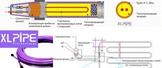
What is a flow meter and its design
Flow meters are used for the initial setting of flows, which is easier, more accurate and faster. In addition, during operation they allow you to evaluate the current flow rate in relation to the one set during setup. To understand the mechanics of adjustment, you need to know how the flow meter is designed and how it works. It is a hollow body with a poppet valve, which is supported by a spring. The spring is calibrated. Its top is formed into a transparent cone with a scale.
How does the Valtek flow meter work?
In order to be able to navigate by the flow values and, in fact, regulate it, a flow indicator is attached to the spring. For supply-mounted flowmeters, the default flow indicator is mounted on the top of the housing. In this position, it points to “0” and the flow is blocked (as in the photo above). If flowmeters are designed for installation on a return manifold, the flow indicator is located at the bottom.
There are two types of flow meters - with and without fixing the position of the adjusting sleeve. The first ones are more reliable, since the settings are not lost, which can happen with regular ones. But they are more expensive. And since the collector unit itself is not cheap, flow meters are often installed without fixation.
How to set the flow on a flow meter
The scale has marks and numbers from 0 to 5. The number indicates the strength of the flow - this is the speed of movement of the coolant in meters per second (m/s). The flow adjustment procedure is as follows:
- Remove (unscrew) the protective cap. On Valtec manifolds they are red.
- Loosen the fixing sleeve. If it is not there, skip this step.
- Scroll the adjusting sleeve until the flow indicator stops at zero.
- We turn it in the opposite direction, setting the required value.
- If there is a fixing sleeve, tighten it until it stops.
- We put on the protective cover.
So, one by one we set the flow meters of each loop of the heated floor. As you understand, without the fixing sleeve there are slightly fewer steps
Please note: it is better not to skip the step with setting zero. This does not take much time, but allows you to check the calibration
Method of adjusting floor heating flow meters
If you do everything according to the rules, you should have a thermal engineering calculation that indicates the flows in each loop. Do you have a plan? Then set the values according to the plan. If not, we will act based on the size of the contours. Provided that pipes of the same cross-section are laid, it will be necessary to change the flow rate based on the required heat transfer. But in this case, it is necessary to know the length of the pipe in each loop.
Let's look at an example. Let us have four circuits: 90 m, two 75 m and 50 m. The procedure for adjusting the flow meters of the Valtek collector is as follows:
- On the longest loop, 90 m long, we open the flow meter completely (if maximum flow is needed) or set the value that is required. Let us assume that for this case the maximum flow rate is 5 m/s. To do this, lower the flow indicator to the very bottom. There is a sign there for 5 m/s.
- Let's calculate the required flow rate for 75 meters. Determined by the length ratio: 75/90 = 0.83. We multiply the flow rate on the first loop (5 m/s) by the resulting figure. It turns out 5 m/s * 0.83 = 4.17 m/s. We set the flow indicator on two 75 m loops just below the 4 m/s mark.
- Using the same scheme, we calculate the flow rate for a 50-meter circuit: 50/90 = 0.55. We calculate the required coolant speed: 5 m/s * 0.55 = 3.7 m/s. We set the flow indicator slightly short of mark 4.
Next, turn on the boiler and check how correctly the collector is configured. With the same length and the same flow rate, it may turn out that one circuit heats much better. This is due to a different installation scheme. A circuit that heats less well most likely has more bends or they are steeper. This increases hydraulic resistance, which reduces the speed of coolant movement. This means less heat is transferred. The solution is to increase the flow rate a little and see the results.
Modules as a principle
The use of ready-made VALTEC units and modules, designed specifically for underfloor heating systems, allows you to quickly solve the problems that arise when creating a water-heated floor.
The use of VALTEC pumping and mixing units and manifold blocks in water heated floor systems saves money and time, and allows you to minimize the likelihood of design and installation errors. The equipment is compact, reliable, easy to use, and its installation does not place excessively high demands on the qualifications of the installer.
At the same time, we offer modules of various functionality, price categories and do not exclude other solutions (in particular, based on mixing valves and thermostatic kits) - where they are more appropriate.
Advantages of the Valtek system
- Exceptionally reliable. High-quality materials and fasteners, the system is equipped with blocks and modules manufactured by the manufacturer itself virtually eliminate the likelihood of errors when performing calculations and design, which already indicates guaranteed stability and efficiency of operation without the risk of leaks.
- The company's product line includes everything that is necessary for installing a heating system, including accompanying materials, for combining it with the future finishing coating, and organizing hydro- and thermal insulation. In other words, everything that will ensure maximum energy efficiency of the heated floor used.
- The manufacturer uses uniform standards in production that ensure full compatibility of all possible structural components, as well as materials.
The choice is for the client
Unlike many other manufacturers of underfloor heating systems, our company provides customers with a flexible approach when choosing equipment and materials. This applies to all groups of products offered.
The ability to maneuver in the configuration of a VALTEC water heated floor allows the customer to provide the level of comfort they require without overpaying for the system, and also to select materials depending on the priority installation technique.
In particular, taking the use of VALTEC PEX-AL-PEX metal-polymer pipes as the base option, we have included in our assortment other types of pipes for built-in heating systems (pipes for water heated floors).
PEX-EVOH pipes
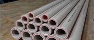
In most cases, the company's specialists recommend using pipes made of cross-linked high-density polyethylene. Currently, the range includes 2 models with diameters of 16 and 20 mm. A system of fittings made of brass alloy is used as connecting elements.
Since cross-linked polyethylene is capable of transmitting oxygen molecules, the surface of the pipelines is covered with a protective layer of polyvinylethylene. If you install simple garden hoses, which look very similar to PEX-EVOH, then saturation of oxygen in the water will lead to rapid rusting of the steel components.
Modern technologies
VALTEC water heated floor is an opportunity to get a system equipped with all modern functions, such as weather-dependent regulation or heating control according to a given time program and/or according to a given room temperature. The level of automation of the system is determined by the wishes of the customer (see section “Automation for controlling water heated floors”).
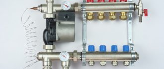
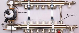
Description of the elements of the collector group
Types of thermal heads for adjusting heated floors, their design and installation options
produces heating equipment for heating systems, radiator and floor. For water heating, a pipe and perforated insulation with fastening elements for the liquid line are purchased.
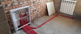
The pipes are connected to a comb, which consists of supply and return manifolds. What does a Valtec fluid distribution block provide?
- Supply manifold; a line with hot coolant is connected to it.
- The unit is equipped with flow meters that monitor the filling of the floor water circuit.
- An end tube with a float device is used to remove air.
- On the return circuit there are outputs for installing a thermal head. If the head is faulty, it is removed for repair. At the same time, the “warm floor” heating system operates in normal mode, without draining the coolant. The thermal head can be replaced with a servo drive or other control device.
- Flow meter valves; they are not permanently mounted on the hot water bar. A threaded connection is provided for them. If necessary, they can be removed.
- The system is equipped with a float device for air removal. A shut-off valve is connected to it, which allows you to remove the float if necessary.
- A drain valve is designed to remove coolant from the heating system. It has a hinged design.
- To ensure that the installation of the collector block for underfloor heating “Valtec” does not cause difficulties, the equipment kit includes adapter nipples and fittings. They are equipped with heat-resistant rubber gaskets.
- The operating temperature of the comb is 90 0C.
- Optimal pressure 8 bar.
- The filling level of the main line is 2.5 m3/h.
Systems that do not include flow meters are cheaper, but if, along with large rooms, the mains of a bathroom or bathroom that are small in size are connected to the comb, then a device for filling the water circuit is necessary.
Along with a thermal head or servos, it regulates the filling of the water circuit and the room temperature. The flow meter is a valve. It closes, preventing hot water from entering a certain circuit. The device is triggered if the coolant flow exceeds the permissible limit.
The Valtek manifold for heated floors is made of stainless steel or nickel-plated brass. Fittings are made from hot-stamped brass. The air vent float is made of polypropylene.
- The size of the collector group depends on the number of outputs. If the block provides 3 outputs, then the length of the tube is 230 mm. With 7 outlets, the comb has a length of 430 mm.
- The pitch between the outlets is 60 mm.
- Outlet size 1”.
The comb is mounted on the wall using brackets. They have a figured design. The edge that fits tightly to the wall surface is provided for the cold circuit. A tube with hot coolant is fixed on the protruding surface.
From tool to fitting
One of the main principles of VALTEC is to offer not individual components of engineering systems, but a range of products for their creation. In relation to water heated floors, this means the presence in our assortment of both basic equipment and building materials, connecting parts and fasteners, and installation tools (“Components for water heated floors”, “Building materials for heated floors”, “Tools for installing pipes” ). In addition to our own brand products, we sell underfloor heating products from our partners; they are presented in the “VALTEC Recommends” section of the catalogue. Getting everything you need from “one source” is beneficial in all respects.
Assembly of the mixing unit
When faced with such a seemingly difficult task, you first need to understand in detail the intricacies of this process. Below is an example of assembling a mixing unit with your own hands; the assembly will be made from metal components.
We will assemble it according to a scheme in which there is a thermostatic three-way mixing valve and a series connection of a circulation pump. To seal the seams, use flax tow and sealant paste; good reviews of Unipack paste.
You will need the following materials:
- Union nuts, American.
- Manual air vent.
- Nipples.
- Circulation pump.
- Thermometer.
- Check valve.
- Ball valve.
- Tees.
We are assembling on the basis of a three-way mixer of the ESBI thermostatic valve; the box indicates in which direction the water is mixed. The operating outlet temperature is 20-43 degrees Celsius, which meets the requirements for a heated floor system. This mixer already contains a thermostatic head, a temperature sensor and a temperature controller that allows you to set the temperature you need. On it itself, arrows indicate in which direction cold and hot water flows.
Wilo has proven itself well in this niche. Having picked it up, inspect it, determine in which direction it pumps liquid. Determine the direction of the drive axis; during installation, it should be located horizontally; this is one of the mandatory operating conditions for pumps that have a wet rotor installed in their design. Another prerequisite is that the switching box cannot be located under the pump.
If, nevertheless, it becomes this way for you, then rotate the upper element of the housing to which the box is connected 180 degrees. This can be done by using a hex wrench to unscrew the four screws that connect the two halves of the pump.
Then carefully rotate the upper element relative to the lower pump element. Put everything back together and tighten the screws. Photo of an example of a mixing unit for heated floors
Photo of an example of a mixing unit for heated floors
The next thing we have to do is to install thermometers on the pipe where the supply takes place before the mixing process, then after the pump. Install the latest one at the outlet of the return manifold. Choose temperature sensors equipped with a probe that screws into central sockets. It would be advisable to verify each device.
Since in one chain they are subject to the same pressure, accordingly, their values should be the same. If possible, check with a reference device. If one of the devices has different readings, you can adjust this yourself. If you remove the cover, you will see a screw that you can use to adjust the readings.
So, the installation steps:
- Assemble the section from the primary supply to the mixing valve, connect the shut-off and ball valves and the tee under the temperature controller. Each of the four taps must be equipped with a union nut. This is done for ease of future maintenance.
- Connect the next outlet of the concentrate to the inlet pipe of the mixer with a three-way valve. Install a thermometer in the central socket of the tee.
- Install a bypass jumper, screw a coupling with an American connection to the second input. This is for ease of installation during maintenance.
- Then connect the tee to the jumper; one side should be facing the return of the system, and the other to the collector.
- The common return element includes one shut-off ball valve. There is no need to install a check valve, since most likely it will not be useful.
- Then assemble a parallel section. Install the temperature sensor by first screwing in the tee.
- Then it was time to assemble the element between the pump and the supply manifold. It includes a coupling with an American connection, a triple connecting element for the temperature regulator, an extension cord, and a shut-off valve.
- Install a ball valve near the manifold.
- Screw the coupling onto the outlet of the mixing valve.
- Well, the almost final stage is the installation of a circulation pump. Insert the rubber O-ring and tighten the nut on the inlet pipe of the pump.
- Screw and crimp the union nut on the other side in the same way. So the mixing unit for the heated floor has been assembled.
This was the final step, then place this element where it will be installed.
Technical support
VALTEC specialists provide customers with technical support at all stages of the creation and operation of water heated floor systems.
- At your disposal:
- free program VALTEC.PRG and training video course on calculating water heated floors;
- a huge amount of reference and educational materials (articles, technical manuals, etc.);
- free training in the format of seminars and webinars;
- video materials on the VALTEC YouTube channel.
You can obtain comprehensive information on VALTEC products, their selection, installation and configuration by contacting VALTEC specialists by phone or using the feedback form on the website.