Author: Yuriy Fedorovich Kolesnikov, thermal power engineer
The induction furnace was invented a long time ago, back in 1887, by S. Farranti. The first industrial installation started operating in 1890 at the Benedicks Bultfabrik company. For a long time, induction furnaces were exotic in the industry, but not due to the high cost of electricity; then it was no more expensive than now. There was still a lot of unknowns in the processes occurring in induction furnaces, and the electronics element base did not allow the creation of effective control circuits for them.
In the induction furnace industry, a revolution has occurred literally before our eyes, thanks to the emergence, firstly, of microcontrollers, the computing power of which exceeds that of personal computers ten years ago. Secondly, thanks to... mobile communications. Its development required the availability of inexpensive transistors capable of delivering power of several kW at high frequencies. They, in turn, were created on the basis of semiconductor heterostructures, for the research of which Russian physicist Zhores Alferov received the Nobel Prize.
Ultimately, induction stoves not only completely transformed the industry, but also became widely used in everyday life. Interest in the subject gave rise to a lot of homemade products, which, in principle, could be useful. But most authors of designs and ideas (there are many more descriptions of which in the sources than functional products) have a poor understanding of both the basics of the physics of induction heating and the potential danger of poorly executed designs. This article is intended to clarify some of the more confusing points. The material is based on consideration of specific structures:
- An industrial channel furnace for melting metal, and the possibility of creating it yourself.
- Induction-type crucible furnaces, the simplest to use and the most popular among home-made furnaces.
- Induction hot water boilers are rapidly replacing boilers with heating elements.
- Household induction cooking appliances that compete with gas stoves and are superior to microwaves in a number of parameters.
Note: all the devices under consideration are based on magnetic induction created by an inductor (inductor), which is why they are called induction. Only electrically conductive materials, metals, etc. can be melted/heated in them. There are also electric induction capacitive furnaces, based on electrical induction in the dielectric between the capacitor plates; they are used for “gentle” melting and electrical heat treatment of plastics. But they are much less common than inductor ones; consideration of them requires a separate discussion, so we’ll leave them for now.
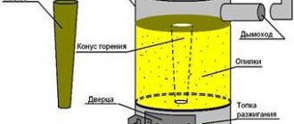
Operating principle
The operating principle of an induction furnace is illustrated in Fig. on right. In essence, it is an electrical transformer with a short-circuited secondary winding:
Operating principle of an induction furnace
- The alternating voltage generator G creates an alternating current I1 in the inductor L (heating coil).
- Capacitor C together with L form an oscillatory circuit tuned to the operating frequency, this in most cases increases the technical parameters of the installation.
- If the generator G is self-oscillating, then C is often excluded from the circuit, using the inductor’s own capacitance instead. For the high-frequency inductors described below, it is several tens of picofarads, which exactly corresponds to the operating frequency range.
- In accordance with Maxwell's equations, the inductor creates an alternating magnetic field with intensity H in the surrounding space. The magnetic field of the inductor can either be closed through a separate ferromagnetic core or exist in free space.
- The magnetic field, penetrating the workpiece (or melting charge) W placed in the inductor, creates a magnetic flux F in it.
- F, if W is electrically conductive, induces a secondary current I2 in it, then the same Maxwell equations.
- If Ф is sufficiently massive and solid, then I2 closes inside W, forming an eddy current, or Foucault current.
- Eddy currents, according to the Joule-Lenz law, release the energy received through the inductor and the magnetic field from the generator, heating the workpiece (charge).
Electromagnetic interaction from the point of view of physics is quite strong and has a fairly high long-range effect. Therefore, despite the multi-stage energy conversion, an induction furnace is capable of showing an efficiency of up to 100% in air or vacuum.
Note: in a medium made of a non-ideal dielectric with a dielectric constant >1, the potentially achievable efficiency of induction furnaces drops, and in a medium with a magnetic permeability >1, it is easier to achieve high efficiency.
Channel furnace
The channel induction melting furnace is the first one used in industry. It is structurally similar to a transformer, see fig. on right:
Channel induction furnace
- The primary winding, powered by a current of industrial (50/60 Hz) or high (400 Hz) frequency, is made of a copper tube cooled from the inside by a liquid coolant;
- Secondary short-circuited winding – melt;
- A ring-shaped crucible made of heat-resistant dielectric in which the melt is placed;
- Magnetic circuit assembled from transformer steel plates.
Channel furnaces are used for melting duralumin, non-ferrous special alloys, and producing high-quality cast iron. Industrial channel furnaces require priming with a melt, otherwise the “secondary” will not short-circuit and there will be no heating. Or arc discharges will appear between the crumbs of the charge, and the entire melt will simply explode. Therefore, before starting the furnace, a little melt is poured into the crucible, and the remelted portion is not poured completely. Metallurgists say that a channel furnace has residual capacity.
A channel furnace with a power of up to 2-3 kW can be made from an industrial frequency welding transformer yourself. In such a furnace you can melt up to 300-400 g of zinc, bronze, brass or copper. You can melt duralumin, but the casting needs to be allowed to age after cooling, from several hours to 2 weeks, depending on the composition of the alloy, so that it gains strength, toughness and elasticity.
Note: duralumin was actually invented by accident. The developers, angry that they could not alloy aluminum, abandoned another “nothing” sample in the laboratory and went on a spree out of grief. We sobered up, returned - and no one had changed color. They checked it - and it gained the strength of almost steel, while remaining as light as aluminum.
The “primary” of the transformer is left standard; it is already designed to operate in the short-circuit mode of the secondary with a welding arc. The “secondary” is removed (it can then be put back and the transformer can be used for its intended purpose), and a ring crucible is put in its place. But trying to convert an HF welding inverter into a channel furnace is dangerous! Its ferrite core will overheat and shatter into pieces due to the fact that the dielectric constant of ferrite is >>1, see above.
The problem of residual capacity in a low-power furnace disappears: a wire of the same metal, bent into a ring and with twisted ends, is placed in the seeding charge. Wire diameter – from 1 mm/kW furnace power.
But a problem arises with a ring crucible: the only material suitable for a small crucible is electroporcelain. It is impossible to process it yourself at home, but where can you get a suitable one? Other refractories are not suitable due to high dielectric losses in them or porosity and low mechanical strength. Therefore, although a channel furnace produces smelting of the highest quality, does not require electronics, and its efficiency already at a power of 1 kW exceeds 90%, they are not used by home-made people.
For a regular crucible
Construction of a crucible induction furnace
The residual capacity irritated metallurgists - the alloys they melted were expensive. Therefore, as soon as sufficiently powerful radio tubes appeared in the 20s of the last century, an idea was immediately born: throw a magnetic circuit onto (we will not repeat the professional idioms of tough men), and put an ordinary crucible directly into the inductor, see fig.
You can’t do this at an industrial frequency; a low-frequency magnetic field without a magnetic circuit concentrating it will spread out (this is the so-called stray field) and give off its energy anywhere, but not into the melt. The stray field can be compensated by increasing the frequency to a high one: if the diameter of the inductor is commensurate with the wavelength of the operating frequency, and the entire system is in electromagnetic resonance, then up to 75% or more of the energy of its electromagnetic field will be concentrated inside the “heartless” coil. The efficiency will be corresponding.
However, already in the laboratories it became clear that the authors of the idea overlooked an obvious circumstance: the melt in the inductor, although diamagnetic, is electrically conductive, due to its own magnetic field from eddy currents, it changes the inductance of the heating coil. The initial frequency had to be set under the cold charge and changed as it melted. Moreover, the range is greater, the larger the workpiece: if for 200 g of steel you can get by with a range of 2-30 MHz, then for a blank the size of a railway tank, the initial frequency will be about 30-40 Hz, and the operating frequency will be up to several kHz.
It is difficult to make suitable automation on lamps; to “pull” the frequency behind the blank requires a highly qualified operator. In addition, the stray field manifests itself most strongly at low frequencies. The melt, which in such a furnace is also the core of the coil, to some extent collects a magnetic field near it, but still, to obtain acceptable efficiency it was necessary to surround the entire furnace with a powerful ferromagnetic screen.
Nevertheless, due to their outstanding advantages and unique qualities (see below), crucible induction furnaces are widely used both in industry and by home-made people. Therefore, let’s take a closer look at how to properly make one with your own hands.
An almost unique brick kiln project
In fact, independent development of a furnace project does not always mean developing a design from scratch. The fact is that finding a scheme that suits you 100% is quite difficult. So we have to make our own adjustments to the existing drawings.
But remember that even after minor, in your opinion, changes, the safety of the stove structure is called into question. Therefore, it is recommended to coordinate your developments with an experienced specialist.
Here are just the main points that even a novice stove maker can change: size, height, presence/absence of a fireplace, etc. In addition, if you are well versed in laying stoves, you will immediately spot all the mistakes made due to carelessness in the order. And in this case, changes to the project are not only possible, but even necessary.
We recommend that you watch the video “The process of creating a 3x5 heating stove project”
A little theory
When designing a homemade “induction”, you need to firmly remember: the minimum power consumption does not correspond to the maximum efficiency, and vice versa. The stove will take the minimum power from the network when operating at the main resonant frequency, Pos. 1 in Fig. In this case, the blank/charge (and at lower, pre-resonant frequencies) operates as one short-circuited turn, and only one convective cell is observed in the melt.
Operating modes of crucible induction furnace
In the main resonance mode, up to 0.5 kg of steel can be melted in a 2-3 kW furnace, but heating the charge/workpiece will take up to an hour or more. Accordingly, the total electricity consumption from the network will be high, and the overall efficiency will be low. At pre-resonant frequencies it is even lower.
As a result, induction furnaces for melting metal most often operate at the 2nd, 3rd, and other higher harmonics (Pos. 2 in the figure). The power required for heating/melting increases in this case; for the same half a kilo of steel, the 2nd one will need 7-8 kW, and the 3rd one 10-12 kW. But warming up occurs very quickly, in minutes or fractions of minutes. Therefore, the efficiency is high: the stove does not have time to “eat” much before the melt can be poured.
Furnaces using harmonics have the most important, even unique advantage: several convective cells appear in the melt, instantly and thoroughly mixing it. Therefore, it is possible to conduct melting in the so-called mode. rapid charge, producing alloys that are fundamentally impossible to smelt in any other melting furnaces.
If you “raise” the frequency 5-6 or more times higher than the main one, then the efficiency drops somewhat (not much), but another remarkable property of harmonic induction appears: surface heating due to the skin effect, displacing EMF to the surface of the workpiece, Pos. 3 in Fig. This mode is rarely used for melting, but for heating workpieces for surface cementation and hardening it is a nice thing. Modern technology would be simply impossible without this method of heat treatment.
About levitation in an inductor
Now let’s do a trick: wind the first 1-3 turns of the inductor, then bend the tube/bus 180 degrees, and wind the rest of the winding in the opposite direction (Pos. 4 in the figure). Connect it to the generator, insert a crucible in the charge into the inductor, and give current. Let's wait until it melts and remove the crucible. The melt in the inductor will gather into a sphere, which will remain hanging there until we turn off the generator. Then it will fall down.
The effect of electromagnetic levitation of the melt is used to purify metals by zone melting, to obtain high-precision metal balls and microspheres, etc. But for a proper result, melting must be carried out in a high vacuum, so here levitation in the inductor is mentioned only for information.
Layouts and assistant programs
Stove makers who want to independently develop designs for brick stoves for their home or cottage can be advised to use computer programs that can be used to make a 3-dimensional project and carefully examine it from all sides in order to find and correct shortcomings.
When the project is ready, take the time to make a miniature oven. What is it for?
- Firstly, the reduced layout allows you to double-check everything for errors.
- Secondly, such layouts are convenient to demonstrate to potential customers (this is the case if you plan to turn stove laying into your personal business). Agree, the client will pay the stated price faster if he clearly understands what product he will receive based on the result of the work.
The bricks for the mini-model are made of wood or dense polystyrene. Size of building material: 13x24x50 mm.
Why an inductor at home?
As you can see, even a low-power induction stove for apartment wiring and consumption limits is too powerful. Why is it worth doing it?
Induction heating for hardening
Firstly, for the purification and separation of precious, non-ferrous and rare metals. Take, for example, an old Soviet radio connector with gold-plated contacts; They did not spare gold/silver for plating back then. We put the contacts in a narrow, high crucible, put them into the inductor, and melt them at the main resonance (professionally speaking, at the zero mode). After melting, we gradually reduce the frequency and power, allowing the blank to harden for 15 minutes to half an hour.
Once it cools down, we break the crucible and what do we see? A brass post with a clearly visible gold tip that just needs to be cut off. Without mercury, cyanide and other deadly reagents. This cannot be achieved by heating the melt from the outside in any way; convection in it will not do so.
Inductor for tempering induction furnace
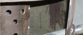
Well, gold is gold, and now there is no black scrap metal lying on the road. But the need for uniform or precisely dosed heating of metal parts over the surface/volume/temperature for high-quality hardening will always be found by a homemaker or individual entrepreneur. And here again an inductor stove will help out, and the electricity consumption will be feasible for the family budget: after all, the main share of heating energy comes from the latent heat of metal melting. And by changing the power, frequency and location of the part in the inductor, you can heat exactly the right place exactly as it should, see fig. higher.
Finally, by making an inductor of a special shape (see figure on the left), you can release the hardened part in the right place, without breaking the hardening carburization at the end/ends. Then, where necessary, use bending, ivy, and the rest remains hard, viscous, elastic. At the end, you can reheat it again where it was released and harden it again.
Let's get to the stove: what you need to know
An electromagnetic field (EMF) affects the human body, at least warming it up in its entirety, like meat in a microwave. Therefore, when working with an induction furnace as a designer, craftsman or operator, you need to clearly understand the essence of the following concepts:
PES – electromagnetic field energy flux density. Determines the general physiological impact of EMF on the body, regardless of the frequency of radiation, because The PES of an EMF of the same intensity increases with increasing radiation frequency. According to sanitary standards of different countries, the permissible PES value is from 1 to 30 mW per 1 sq. m. of body surface with constant (more than 1 hour per day) exposure and three to five times more with a single short-term, up to 20 minutes.
Note: the United States stands apart; its permissible power consumption is 1000 mW (!) per square meter. m. body. In fact, Americans consider the beginning of physiological effects to be external manifestations, when a person already becomes ill, and the long-term consequences of EMF exposure are completely ignored.
The PES decreases with distance from a point source of radiation by the square of the distance. Single-layer shielding with galvanized or fine-mesh galvanized mesh reduces the PES by 30-50 times. Near the coil along its axis, the PES will be 2-3 times higher than at the side.
Let's explain with an example. There is a 2 kW and 30 MHz inductor with an efficiency of 75%. Therefore, 0.5 kW or 500 W will go out of it. At a distance of 1 m from it (the area of a sphere with a radius of 1 m is 12.57 sq. m.) per 1 sq. m. will have 500/12.57 = 39.77 W, and per person - about 15 W, this is a lot. The inductor must be positioned vertically, before turning on the furnace, put a grounded shielding cap on it, monitor the process from a distance, and immediately turn off the furnace when it is completed. At a frequency of 1 MHz, the PES will drop by a factor of 900, and a shielded inductor can be operated without special precautions.
Microwave – ultra high frequencies. In radio electronics, microwave frequencies are considered to be so-called. Q-band, but according to microwave physiology it starts at about 120 MHz. The reason is electrical induction heating of cell plasma and resonance phenomena in organic molecules. Microwave has a specifically targeted biological effect with long-term consequences. It is enough to receive 10-30 mW for half an hour to undermine health and/or reproductive capacity. Individual susceptibility to microwaves is extremely variable; When working with him, you need to regularly undergo a special medical examination.
It is very difficult to suppress microwave radiation; as the pros say, it “siphons” through the slightest crack in the screen or with the slightest violation of the grounding quality. Effective combating of microwave radiation from equipment is possible only at the level of its design by highly qualified specialists.
Fortunately, the frequency range in which induction furnaces operate does not extend to microwaves. But if it is poorly designed or used, the oven can enter a mode in which parasitic microwave frequencies appear. Of course, this should be avoided at all costs.
Features of use
The oven is easy to use. To warm up the product you need to do the following:
- Load pallets into wood stove. Gas and electric models are connected to the gas pipeline and the electrical network, respectively.
- Dry the heating element after idle time in an electric oven. Other types can be enabled immediately.
- Select the desired program mode.
- Preheat the chimney for 6-7 minutes.
- Check the thermostat indicators. The temperature is maintained automatically in most modern models.
If the oven is used for cooking, you need to open the lid and place sheets of kitchen utensils into the oven. After finishing, the device turns off. It should not be kept in working condition for more than an hour.
Furnace components
Inductor
The most important part of an induction furnace is its heating coil, the inductor. For homemade stoves with a power of up to 3 kW, an inductor made of a bare copper tube with a diameter of 10 mm or a bare copper bus with a cross-section of at least 10 square meters will be used. mm. The internal diameter of the inductor is 80-150 mm, the number of turns is 8-10. The turns should not touch, the distance between them is 5-7 mm. Also, no part of the inductor should touch its shield; the minimum gap is 50 mm. Therefore, in order to pass the coil leads to the generator, it is necessary to provide a window in the screen that does not interfere with its removal/installation.
The inductors of industrial furnaces are cooled with water or antifreeze, but at a power of up to 3 kW, the inductor described above does not require forced cooling when operating for up to 20-30 minutes. However, it itself becomes very hot, and scale on copper sharply reduces the efficiency of the furnace until it loses its functionality. It is impossible to make a liquid-cooled inductor yourself, so it will have to be changed from time to time. You cannot use forced air cooling: the plastic or metal fan housing near the coil will “attract” EMFs to itself, overheat, and the efficiency of the furnace will drop.
Note: for comparison, an inductor for a melting furnace for 150 kg of steel is bent from a copper pipe with an outer diameter of 40 mm and an inner diameter of 30 mm. The number of turns is 7, the inside diameter of the coil is 400 mm, and the height is also 400 mm. To power it up in zero mode, you need 15-20 kW in the presence of a closed cooling circuit with distilled water.
Generator
The second main part of the furnace is the alternator. It’s not worth even trying to make an induction furnace without knowing the basics of radio electronics at least at the level of an average radio amateur. Operating is the same, because if the stove is not under computer control, you can set it to mode only by feeling the circuit.
Generator circuit for an induction furnace, giving parasitic microwave frequency
When choosing a generator circuit, you should in every possible way avoid solutions that give a hard current spectrum. As an anti-example, we present a fairly common circuit using a thyristor switch, see Fig. higher. A calculation available to a specialist based on the oscillogram attached to it by the author shows that the PES at frequencies above 120 MHz from an inductor powered in this way exceeds 1 W/sq. m at a distance of 2.5 m from the installation. Deadly simplicity, to say the least.
Tube generator circuit for induction furnace
As a nostalgic curiosity, we also present a diagram of an ancient tube generator, see fig. on right. These were made by Soviet radio amateurs back in the 50s, Fig. on right. Setting to mode - with an air capacitor of variable capacitance C, with a gap between the plates of at least 3 mm. Works only on zero mode. The setting indicator is a neon light bulb L. The peculiarity of the circuit is a very soft, “lamp” radiation spectrum, so this generator can be used without special precautions. But - alas! – you can’t find lamps for it now, and with a power in the inductor of about 500 W, the power consumption from the network is more than 2 kW.
Note: the frequency of 27.12 MHz indicated in the diagram is not optimal, it was chosen for reasons of electromagnetic compatibility. In the USSR, it was a free (“junk”) frequency, for which permission was not required to operate, as long as the device did not interfere with anyone. In general, C the generator can be tuned in a fairly wide range.
Homemade crucible induction furnace from the 50s.
In the next fig. on the left is a simple self-excited generator. L2 – inductor; L1 – feedback coil, 2 turns of enameled wire with a diameter of 1.2-1.5 mm; L3 – blank or charge. The inductor's own capacitance is used as a loop capacitance, so this circuit does not require adjustment, it automatically enters the zero mode mode. The spectrum is soft, but if the phasing of L1 is incorrect, the transistor instantly burns out, because it turns out to be in active mode with a DC short circuit in the collector circuit.
Circuit of the simplest generator for an induction furnace
Also, the transistor can burn out simply from a change in the external temperature or self-heating of the crystal - no measures are provided to stabilize its mode. In general, if you have old KT825 or similar ones lying around somewhere, then you can start experiments on induction heating with this circuit. The transistor must be installed on a radiator with an area of at least 400 square meters. see with blowing from a computer or similar fan. Adjustment of the capacity in the inductor, up to 0.3 kW, by changing the supply voltage within 6-24 V. Its source must provide a current of at least 25 A. The power dissipation of the resistors of the basic voltage divider is at least 5 W.
Multivibrator generator for induction furnace
The diagram follows. rice. on the right is a multivibrator with an inductive load using powerful field-effect transistors (450 V Uk, at least 25 A Ik). Thanks to the use of capacitance in the oscillatory circuit circuit, it produces a rather soft spectrum, but out-of-mode, therefore suitable for heating parts up to 1 kg for quenching/tempering. The main disadvantage of the circuit is the high cost of components, powerful field switches and high-speed (cutoff frequency of at least 200 kHz) high-voltage diodes in their base circuits. Bipolar power transistors in this circuit do not work, overheat and burn out. The radiator here is the same as in the previous case, but airflow is no longer needed.
The following scheme already claims to be universal, with a power of up to 1 kW. This is a push-pull generator with independent excitation and bridge-connected inductor. Allows you to work in mode 2-3 or in surface heating mode; the frequency is regulated by a variable resistor R2, and the frequency ranges are switched by capacitors C1 and C2, from 10 kHz to 10 MHz. For the first range (10-30 kHz), the capacitance of capacitors C4-C7 should be increased to 6.8 μF.
Scheme of a universal generator for an induction furnace
The transformer between the stages is on a ferrite ring with a cross-sectional area of the magnetic core of 2 square meters. see Windings - made of enameled wire 0.8-1.2 mm. Transistor radiator – 400 sq. see for four with airflow. The current in the inductor is almost sinusoidal, so the radiation spectrum is soft and no additional protective measures are required at all operating frequencies, provided that it works for up to 30 minutes a day after 2 days on the 3rd.
Video: homemade induction heater in action
Stove with hot water boiler and stove bench
In addition to the simplest option with two fireboxes, they build complex Russian stoves with their own hands with a stove bench, a boiler for heating water, with a firebox or a fireplace. Let's consider the order of popular solutions that can be used for self-construction.
The ordering greatly simplifies the laying, since the graphic representation and description of each row shows exactly how the previous row differs from the next, and what elements are needed at all stages.
Let's look at the diagrams for the construction of a Russian stove with a boiler , created in a computer program.
Row 1 determines the location of the entire structure; it is made of solid refractory bricks laid flat.
Before laying, it is necessary to make markings, build a foundation, and lay a layer of waterproofing. It is better to first lay out all the elements on a dry surface to determine the dimensions of the oven
Row 2 – the beginning of the construction of compartments.
First, the bricks that make up the walls of the furnace are laid out, then a series of internal partitions are laid out. Bricks should be laid strictly according to the drawing, measuring each row with a level
Row 3 – design of two chambers, a cleaning chamber and a blower chamber.
Cast iron doors are installed opposite the chambers. For fixation, a wire is used, which is inserted into the ears of the products at one end, and placed into the seams between the bricks with the other.
Row 4 – closing the hearth.
One chamber inside the structure - underneath - is closed with bricks laid flat. In the same way, the internal channels at the walls are blocked
Row 5 – grate.
The large firebox is equipped with a grate; at the same stage, another door is installed - for the small firebox. Internal masonry is carried out with fireclay bricks without the use of mortar
Row 6 – water heating tank.
A rectangular tank made of galvanized steel and intended for heating water is installed on the side, but so that the approach to it is open
Row 7 – reinforcement of the side wall.
The wall is screeded with a steel strip. At the same time, install the door for the main firebox and the grate for the small one. Gaps on the internal masonry increase heat transfer
Rows 8 and 9 – removal of channels.
The laying of internal channels is carried out strictly according to the scheme and level. Another door is also installed here - this time for a small firebox
Row 10 – combining the arches of the main and small fireboxes.
Here the bottom of the crucible is laid out completely. The water heating tank is completely closed. Only the openings for the passage of heated air to the cooking chamber are left open.
Row 11 – installation of the hob.
The best place for installation is on the edge of the front wall, above the doors to both combustion chambers. A steel angle of 50*50 mm is suitable for fixing the plate. At the rear there is a grate
Rows 12-13 – design of the walls of the hob.
At this stage, the construction of the chimney begins. A metal damper should be installed between the chimney and the furnace, closing the opening if necessary
Row 14 – entrance to the pipe.
The design of the smoke exhaust channel begins. The hole in it opens using a flap installed vertically. The walls of the crucible continue to rise
Row 15 – arch of the cooking chamber
The direction of the masonry changes - it narrows to form and cover the cooking chamber. The outline of a chimney appears
Row 16 – strengthening the walls.
The masonry is made according to the 15th row principle, but for the reliability of the structure, steel plates with locking elements at the ends are placed in the seams
Row 17 – installation of metal parts.
The back wall is screeded with a metal strip, the roof of the cooking chamber is further narrowed, steel supports are installed above the cooking plate for subsequent masonry - a corner and a strip
Row 18 – crucible arch.
To create an arched vault structure, either a template or a metal frame is used. The bricks are laid out on a long edge called a spoon. The hob is closed
Row 19 – strengthening the internal partition.
For reinforcement, as usual, a steel strip is used. Walls are laid around the perimeter of the vault, which will serve as sides for further backfilling.
Row 20 – filling with sand.
The space above the furnace is completely filled with clean sifted sand, which must be carefully insulated. The filling increases the heat capacity of the bread baking chamber
Row 21 – base of the bed.
In the rear part, compacted sand and the walls adjacent to the arch are completely covered with masonry - this is the base of the future bed; in front the over-pipe is narrowed
Row 22 – installation of a metal part in the chimney.
To increase heating time, contain heat and be able to redirect gases, a metal element with a hole is installed in the chimney
Row 23 – chimney door.
To clean the chimney, you need a special hole, closed with a door that is fixed with a wire. Removal of the overtube continues
Row 24 – installation of the damper.
The damper is necessary to regulate the draft both in the furnace and in the fireboxes. First, install the canvas along which it moves, and then the valve itself
Row 25-26 – narrowing of the masonry.
The two rows are laid out almost identically, the main goal is to cover the space above the installed valve and form the upper part of the oven
Rows 27-29 – connection of the overpipe and chimney.
The laying of the main parts is completed, the construction of the pipe continues - up to the cutting level. The part of the chimney passing through the ceiling is reinforced not with clay, but with cement mortar
The chimney is led through the attic to the roof, where an otter is installed and the adjacent area is waterproofed so that there are no gaps between the chimney and the roofing material.
The main thing during construction is to follow the order of the Russian stove and monitor the quality of the materials used.
Induction boilers
Induction hot water boilers will undoubtedly replace boilers with heating elements wherever electricity is cheaper than other types of fuel. But their undeniable advantages have also given rise to a lot of homemade products, which sometimes literally make a specialist’s hair stand on end.
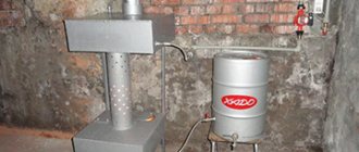
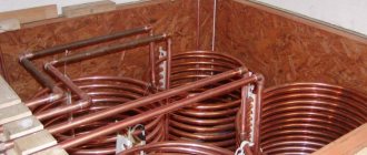
Let's say this design: a propylene pipe with running water is surrounded by an inductor, and it is powered by a 15-25 A HF welding inverter. An option is to make a hollow donut (torus) from heat-resistant plastic, pass water through the pipes, and wrap it around it for heating bus, forming an inductor rolled into a ring.
EMF will transfer its energy to water well; It has good electrical conductivity and an abnormally high (80) dielectric constant. Remember how the remaining droplets of moisture on the dishes shoot out in the microwave.
But, firstly, to fully heat an apartment or private house in winter you need at least 20 kW of heat, with careful insulation from the outside. 25 A at 220 V provide only 5.5 kW (how much does this electricity cost according to our tariffs?) with 100% efficiency. Okay, let's say we're in Finland, where electricity is cheaper than gas. But the consumption limit for housing is still 10 kW, and for excess you have to pay at an increased tariff. And the apartment wiring will not withstand 20 kW; you need to pull a separate feeder from the substation. How much will such work cost? If the electricians are still far from overpowering the area, they will allow it.
Then, the heat exchanger itself. It should either be massive metal, then only induction heating of the metal will work, or made of plastic with low dielectric losses (propylene, by the way, is not one of these, only expensive fluoroplastic is suitable), then the water will directly absorb the EMF energy. But in any case, it turns out that the inductor heats the entire volume of the heat exchanger, and only its inner surface transfers heat to the water.
As a result, at the cost of a lot of work and risk to health, we get a boiler with the efficiency of a cave fire.
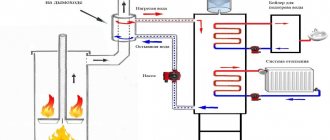
An industrial induction heating boiler is designed in a completely different way: simple, but impossible to do at home, see fig. on right:
Diagram of an induction hot water boiler
- The massive copper inductor is connected directly to the network.
- Its EMF also heats a massive metal labyrinth-heat exchanger made of ferromagnetic metal.
- The labyrinth simultaneously isolates the inductor from water.
Such a boiler costs several times more than a conventional one with a heating element, and is suitable only for installation on plastic pipes, but in return it provides a lot of benefits:
- It never burns out - there is no hot electric coil in it.
- The massive labyrinth reliably shields the inductor: PES in the immediate vicinity of the 30 kW induction boiler is zero.
- Efficiency – more than 99.5%
- Absolutely safe: the intrinsic time constant of the highly inductive coil is more than 0.5 s, which is 10-30 times longer than the response time of the RCD or machine. It is further accelerated by the “recoil” from the transient process when the inductance breaks down on the housing.
- The breakdown itself, due to the “oakiness” of the structure, is extremely unlikely.
- Does not require separate grounding.
- Indifferent to lightning strikes; It cannot burn a massive coil.
- The large surface of the labyrinth ensures effective heat exchange with a minimum temperature gradient, which almost eliminates the formation of scale.
- Enormous durability and ease of use: the induction boiler, together with a hydromagnetic system (HMS) and a sediment filter, operates without maintenance for at least 30 years.
About homemade boilers for hot water supply
Diagram of an induction water heater for hot water supply
Here in Fig. A diagram of a low-power induction heater for hot water systems with a storage tank is shown. It is based on any power transformer of 0.5-1.5 kW with a primary winding of 220 V. Dual transformers from old tube color TVs - “coffins” on a two-rod magnetic core of the PL type - are very suitable.
The secondary winding is removed from such windings, the primary is rewound onto one rod, increasing the number of its turns to operate in a mode close to a short circuit (short circuit) in the secondary. The secondary winding itself is water in a U-shaped pipe bend surrounding another rod. Plastic pipe or metal – it makes no difference at industrial frequency, but the metal pipe must be isolated from the rest of the system with dielectric inserts, as shown in the figure, so that the secondary current is closed only through water.
In any case, such a water heater is dangerous: a possible leak is adjacent to the winding under mains voltage. If you are going to take such a risk, then you need to drill a hole in the magnetic circuit for the grounding bolt, and first of all, tightly ground the transformer and the tank with a steel busbar of at least 1.5 square meters. cm (not sq. mm!).
Next, the transformer (it should be located directly under the tank), with a double-insulated power cable connected to it, a ground electrode and a water-heating coil, is poured into one “doll” with silicone sealant, like an aquarium filter pump motor. Finally, it is highly advisable to connect the entire unit to the network via a high-speed electronic RCD.
Video: “induction” boiler based on household tiles
Types of chamber electric furnaces with bogie hearths
| Furnace designation | Max. temp., °С | Slave. production, mm (width×length×height) (A×B×C) | Gab. dimensions, (width×length×height), mm (D×E×F) | Power heating | Furnace weight |
| SDO 10.20.8/12 | 1200 | 1000×2000×800 | 1700×5720×2850 | 115 | 2600 |
| SDO 12.20.10/12 | 1200 | 1200×2000×1000 | 1900×5720×3200 | 130 | 3000 |
| SDO 15.18.12/12 | 1200 | 1500×1800×1200 | 2900×4000×3500 | 135 | 4500 |
| SDO 15.30.10/10 | 1000 | 1500×3000×1000 | 2900×7000×3400 | 250 | 8000 |
| SDO 20.25.15/10 | 1000 | 2000×2500×1500 | 3400×6500×4500 | 260 | 9200 |
| SDO 20.40.15/10 | 1000 | 2000×4000×1500 | 3400×9000×4500 | 380 | 14000 |
| SDO 25.50.20/10 | 1000 | 2500×5000×2000 | 4000×12500×5400 | 600 | 25000 |
Inductor in the kitchen
Induction hob
Induction hobs have become commonplace in the kitchen, see fig. According to the principle of operation, this is the same induction stove, only the bottom of any metal cooking vessel acts as a short-circuited secondary winding, see fig. on the right, and not just from ferromagnetic material, as the ignorant often write. Aluminum cookware is simply falling out of use; doctors have proven that free aluminum is a carcinogen, and copper and tin have long been out of use due to toxicity.
Household induction cookers are a product of the age of high technology, although the idea arose simultaneously with induction melting furnaces. Firstly, to isolate the inductor from the cooking, a durable, resistant, hygienic and EMF-free dielectric was needed. Suitable glass-ceramic composites have come into production relatively recently, and the top plate of the slab accounts for a significant portion of its cost.
Kitchen induction hob diagram
Then, all cooking vessels are different, and their contents change their electrical parameters, and the cooking modes are also different. A specialist will not be able to do this by carefully tightening the knobs to the desired fashion; you need a high-performance microcontroller. Finally, according to sanitary requirements, the current in the inductor must be a pure sinusoid, and its magnitude and frequency must vary in a complex way according to the degree of readiness of the dish. That is, the generator must have digital generation of the output current, controlled by the same microcontroller.
There is no point in making a kitchen induction hob yourself: more money will be spent on electronic components alone at retail prices than on ready-made good tiles. And it’s still quite difficult to control these devices: anyone who has one knows how many buttons or sensors there are with the inscriptions: “Stew”, “Roast”, etc. The author of this article saw a tile that separately listed “Navy Borscht” and “Pretanier Soup.”
However, induction cookers have many advantages over others:
- Almost zero, unlike microwave ovens, PPE, even if you sit on this tile yourself.
- Possibility of programming for preparing the most complex dishes.
- Melting chocolate, rendering fish and poultry fat, preparing caramel without the slightest sign of burning.
- High efficiency as a result of fast heating and almost complete concentration of heat in the cooking vessel.
Heating up cooking utensils on an induction hob and gas burner
To the last point: take a look at fig. on the right, there are schedules for heating up cooking on an induction stove and a gas burner. Anyone who is familiar with integration will immediately understand that an inductor is 15-20% more economical, and there is no need to compare it with a cast-iron “pancake”. The cost of money on energy when preparing most dishes for an induction cooker is comparable to that of a gas cooker, and even less for stewing and cooking thick soups. The inductor is so far inferior to gas only during baking, when uniform heating is required on all sides.
Video: failed induction heater from a kitchen stove
Choosing a furnace design for our project
To ensure your furnace is as efficient as possible, pay attention to the following points...
- Dimensions
. When determining the required dimensions, remember that the side walls give off much more heat than the front and back. You should not choose massive models (for example, a Russian stove) for small spaces. Firstly, it will look ridiculous. Secondly, to heat such a stove, you will need a lot of fuel. - Location
. Taking into account the size of all the walls, think about how to position the stove so that it heats not only one room, but possibly also adjacent ones. If this is a heating and cooking model, then the hob is turned towards the kitchen, and the body of the stove itself is brought into the living room. Also, structures that perform only a heating function are often located at the junction of 3 or even 4 rooms so that the walls of the stove are also partitions. - Form
. The shape of the stoves can be square, rectangular, T-shaped, as well as with functional protrusions in the form of a stove bench or hob. Think in advance what tasks your stove will perform, and from there “dance” with the choice of shape. - Heat dissipation
. When building a stove with your own hands, calculate what kind of heat output it should have in order to cope with heating the premises. The required heat output of the stove depends not only on the area of the room, but also on its location. For example, to heat a hallway, a stove with a larger surface area is required than to maintain heat in rooms with one or two external corners (with equal area). And in order for a comfortable temperature to be established in a living room of the same size, which does not have external corners, the smallest heating model will be enough. - Insulation of the building.
The efficiency of a heating device, or rather, the effect of its operation, also depends on how conscientiously the work on insulating the house was carried out. If the walls, floor, ceiling and windows do not allow large heat losses, then even a relatively small stove will be enough to create comfortable living conditions. But if the wind is literally blowing through the house, even the most massive stove structure will not save you.