Hello friends!
We continue the topic of heating and today I want to talk to you about choosing the diameter of polypropylene pipes that will be used for heating. When designing and installing a heating system, the question always arises: what pipeline diameter to choose.
The choice of diameter, and therefore the throughput of pipes, is important, because you need to ensure the coolant speed is within 0.4 - 0.6 meters per second, which is recommended by experts. In this case, the required amount of energy (amount of coolant) must be supplied to the radiators.
It is known that if the speed is less than 0.2 m/s, then air jams will stagnate. A speed greater than 0.7 m/s should not be done for reasons of energy saving, since the resistance to fluid movement becomes significant (it is directly proportional to the square of the speed), moreover, this is the lower limit for the occurrence of noise in pipelines of small diameters.
What pipes should be used for the heating system?
Polypropylene pipes are divided into several types, which have their own technical characteristics, and they are intended for different conditions. PN25 (PN30) brands are suitable for heating, which can withstand a working pressure of 2.5 atm at a liquid temperature of up to 120 degrees. WITH.
Data on wall thickness are given in the tables.
For heating, polypropylene pipes are now used, which are reinforced with aluminum foil or fiberglass. The reinforcement prevents significant expansion of the material when heated.
Many experts prefer pipes with internal fiberglass reinforcement. Such a pipeline has recently become most widely used in private heating systems.
Questions about selecting the diameter of the heating pipeline
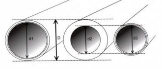
Pipes are produced in standard diameters, from which you need to make a choice. Standard solutions have been developed for selecting pipe diameters for heating a house, based on which in 99% of cases you can make the optimal correct choice of diameter without performing a hydraulic calculation.
Standard outer diameters of polypropylene pipes are 16, 20, 25, 32, 40 mm. The internal diameter of PN25 pipes corresponding to these values is 10.6, 13.2, 16.6, 21.2, 26.6 mm, respectively.
More detailed information on the outer diameters, inner diameters and wall thickness of polypropylene pipes is given in the table.
What diameters should I connect?
We need to ensure the supply of the required thermal power, which will directly depend on the amount of coolant supplied, but the fluid speed must remain within the specified limits of 0.3 - 0.7 m/s
Then the following correspondence of connections arises (for polypropylene pipes the outer diameter is indicated):
- 16 mm - for connecting one or two radiators;
- 20 mm – for connecting one radiator or a small group of radiators (radiators of “regular” power within 1 - 2 kW, maximum connected power - up to 7 kW, number of radiators up to 5 pcs.);
- 25 mm – for connecting a group of radiators (usually up to 8 pieces, power up to 11 kW) of one wing (arm of a dead-end wiring diagram);
- 32 mm – for connecting one floor or an entire house, depending on the thermal power (usually up to 12 radiators, respectively, thermal power up to 19 kW);
- 40 mm - for the main line of one house, if any (20 radiators - up to 30 kW).
Let us consider the choice of pipe diameter in more detail, based on pre-calculated tabular correspondences of energy, speed and diameter.
Selection of pipes by power
The table shows that at a speed of 0.4 m/s, approximately the following amount of heat will be supplied through polypropylene pipes of the following outer diameter:
- 4.1 kW - internal diameter about 13.2 mm (outer diameter 20 mm);
- 6.3 kW - 16.6 mm (25mm);
- 11.5 kW - 21.2 mm (32 mm);
- 17 kW - 26.6 mm (40 mm);
And at a speed of 0.7 m/s, the supplied power values will be approximately 70% greater, which is not difficult to find out from the table.
How much heat do we need?
How much heat should the pipeline supply?
Let's take a closer look at the example of how much heat is usually supplied through pipes, and select the optimal pipeline diameters.
There is a house with an area of 250 sq. m., which is well insulated (as required by the SNiP standard), so it loses heat in the winter by 1 kW per 10 sq. m. To heat the entire house, 25 kW of energy is required (maximum power). For the first floor - 15 kW. For the second floor - 10 kW.
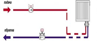
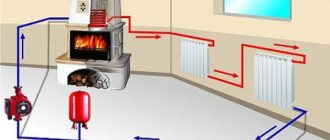
Our heating scheme is two-pipe. One pipe supplies hot coolant, and the other pipe cools it to the boiler. Radiators are connected in parallel between the pipes.
On each floor, the pipes branch into two wings with the same thermal power, for the first floor - 7.5 kW, for the second floor - 5 kW.
So, 25 kW comes from the boiler to the interfloor branch. Therefore, we will need main pipes with an internal diameter of at least 26.6 mm so that the speed does not exceed 0.6 m/s. A 40mm polypropylene pipe is suitable.
From the interfloor branching - along the first floor to the branching on the wings - 15 kW is supplied. Here, according to the table, for a speed of less than 0.6 m/s, a diameter of 21.2 mm is suitable, therefore, we use a pipe with an outer diameter of 32 mm.
7.5 kW goes to the wing of the 1st floor - an internal diameter of 16.6 mm is suitable, - polypropylene with an outer diameter of 25 mm.
For each radiator, the power of which does not exceed 2 kW, you can make an outlet with a pipe with an outer diameter of 16 mm, but since this installation is not technologically advanced, the pipes are not popular; a 20 mm pipe with an inner diameter of 13.2 mm is more often installed.
Accordingly, we use a 32mm pipe on the second floor before branching, a 25mm pipe on the wing, and we also connect the radiators on the second floor with a 20mm pipe.
As you can see, it all comes down to a simple choice among the standard diameters of commercially available pipes. In small home systems, up to a dozen radiators, in dead-end distribution circuits, 25 mm polypropylene pipes are mainly used - “per wing”, 20 mm - “per device”. and 32 mm “to the main line from the boiler”.
Mounting sleeves
Installation of the heating system is impossible without the use of mounting sleeves. When laying a pipeline through walls and ceilings, the walls of the products come into contact with an aggressive environment.
Due to physical laws, pipes during operation will undergo periodic contraction and expansion. This will lead to mechanical stress on the surface, guaranteeing faster wear at the contact points. To avoid this, SNIP building codes provide for the supply of pipelines with additional structural parts called sleeves.
- prevent the leakage of liquids from adjacent rooms or the street;
- prevent the passage of unnecessary gaseous substances;
- maintain sound insulation;
- ensure the integrity of the structure when dismantling or replacing the pipeline;
- prevent unwanted insects from entering the premises.
The pipeline can pass through any building in two planes: vertical (floors, floors, ceilings) and horizontal (internal and external walls, ceilings).
The sleeve consists of:
- Covers (standard or cut from steel or polymer pipes).
- Packings (filling the cavity between the pipeline and the cover), which can be a soft, non-combustible material. It is possible to use special cement or clay mixtures.
The size of the sleeve assembly is determined by the outer diameter of the pipeline and the thickness of the wall or ceiling: the size of the sleeve and the length of the product should be 10–20 mm larger.
This video will briefly introduce you to the installation of a heating system in an apartment.
General information about heating pipes
All pipes for heating systems can be divided into two types: metal and polymer.
- copper;
- metal-plastic;
- bronze;
- metal corrugated;
- steel.
Copper pipes are superior to all others in the following parameters: long service life, smoothness, which increases the speed of coolant movement, and resistance to ultraviolet radiation.
- polyvinyl chloride (PVC);
- polyethylene terephthalate (PET);
- metal-plastic;
- polyurethane;
- propylene;
- polypropylene.
The cross-sectional diameter in which propylene and polypropylene pipes are offered can be in the range of 16-110 mm. The advantages of this material include: relatively low weight, ease of processing and installation work, low price.
Features of choosing other equipment
Pipe diameters can also be selected according to the conditions of hydraulic resistance for atypically long pipeline lengths, at which the technical characteristics of the pumps may be exceeded.
But this can happen for production workshops, but practically never occurs in private construction.
For a house up to 150 sq. m., according to the conditions of the hydraulic resistance of the heating and radiator system, a pump of type 25 - 40 (pressure 0.4 atm) is always suitable; it can also be suitable up to 250 sq. m. in some cases, and for houses up to 300 sq. m. . – 25 – 60 (pressure up to 0.6 atm).
The pipeline is designed for maximum capacity. But the system, if it ever operates in this mode, will not last for a long time. When designing a heating pipeline, you can take parameters such that at maximum load, the coolant speed is 0.7 m/s.
In practice, the speed of water in heating pipes is set by a pump that has 3 rotor speeds.
In addition, the supplied power is regulated by the temperature of the coolant and the duration of operation of the system, and in each room it can be adjusted by disconnecting the radiator from the system using a thermal head with a push valve.
Thus, with the diameter of the pipeline we ensure that the speed is within the range of up to 0.7 m at maximum power, but the system will generally operate with a lower fluid speed.
Source: teplodom1.ru/radiattopl/114-kakoy-diametr-trub-iz-polipropilena-dlya-otopleniya.html
Required data for calculation
The main task of heating pipes is to deliver heat to the heated elements (radiators) with minimal losses. We will build on this when choosing the correct pipe diameter for heating a house. But to calculate everything correctly, you need to know:
- pipe length;
- heat loss in the building;
- element power;
- what kind of pipe layout will be (natural, forced, single-pipe or two-pipe circulation).
The next point, after you have all the above data in your hands, will be necessary to sketch out a general diagram: how, what and where it will be located, what thermal load each heating element will carry.
Then you can begin to calculate the required cross-section of the diameter of the pipe for heating the house. You should also be careful when purchasing:
- metal-plastic and steel pipes are marked by the size of the internal diameter, there are no problems here;
- but polypropylene and copper - by outer diameter. Therefore, we need to either measure the internal diameter ourselves using a caliper, or subtract the wall thickness from the external diameter of the pipe for heating the house.
Don’t forget about this, because we need exactly the “inner diameter of the pipe for heating the house” in order to calculate everything correctly.
Preliminary actions
Even before all the necessary equipment, pipes and elements for them are purchased, it is necessary to legalize the change of the riser in the apartment, if it is not planned.
To do this you need:
- Submit an application for replacement of heating pipes to the housing office long before the start of the heating season (be sure to indicate why replacement is required).
- Then the application will “migrate” to the organization of the heating network.
- An employee of the management company is obliged to come and check the validity of the request to replace the riser. If it is caused by an emergency condition of the pipes, then all costs for dismantling the old system and installing a new one are borne by the organization. In the event that residents decide to replace old risers with new ones in order to reduce heat loss (this reason is considered valid), then all work is paid for by the owner of the property.
- It is necessary to collect the signatures of neighbors who agree to such work , present them to the management company, and only after all permits have been received, begin to dismantle the old pipes.
If the heating risers in an apartment building are in emergency condition, then there is no need to collect signatures, since such a situation requires urgent intervention and repair.
As a rule, there are no prohibitions on unauthorized replacement of pipes in critical condition. Therefore, if the management delays the start of work, then in order to protect property, you can begin to dismantle and install new risers without permits, but only during the non-heating period.
Choosing the diameter for your heating
Do not expect that you will immediately be able to select the correct pipe diameter for heating your home. The fact is that you can achieve the desired efficiency in different ways.
Now in more detail. What is most important in a proper heating system? The most important thing is uniform heating and delivery of liquid to all heating elements (radiators).
In our case, this process is constantly supported by the pump, thanks to which, over a specific time period, the liquid moves through the system. Therefore, we can only choose from two options:
- buy pipes with a large cross-section and, as a result, a low flow rate of coolant;
- or a pipe with a small cross-section, naturally the pressure and speed of the fluid will increase.
Logically, of course, it is better to choose the second option for the diameter of the pipes for heating the house, and for these reasons:
- when laying pipes externally, they will be less noticeable;
- when laying internally (for example, in a wall or under the floor), the grooves in the concrete will be more accurate and easier to chisel;
- the smaller the diameter of the product, the cheaper it is, naturally, which is also important;
- with a smaller pipe cross-section, the total volume of coolant also decreases, thanks to which we save fuel (electricity) and reduce the inertia of the entire system.
And working with a thin pipe is much easier and simpler than with a thick one.
How everything works
First, some general information.
Hot water supply and heating of an apartment building begins with the introduction of a heating main into the house. Two lines are led through the foundation from the nearest thermal chamber - supply (through which process water, also known as the coolant, enters the building) and return (the water, accordingly, returns to the thermal power plant or boiler room, giving off heat).
In the thermal chamber at the entrance to the house (as an option - at the group entrance to several houses located in close proximity to each other) there are shut-off valves or taps.
The heating point, also known as the elevator unit, combines several functions:
- Provides a minimum temperature difference between the supply and return of the heating system;
Reference: the upper peak of the supply temperature is 150 degrees, while according to the temperature schedule, the return flow should return to the thermal power plant cooled to 70°C. However, such a difference would mean extremely uneven heating of the heating devices, so water with a more modest temperature - up to 95 degrees - flows from the elevator into the heating circuit.
- Organizes the supply of hot water to the hot water system and its shutdown throughout the house in case of accidents and routine repairs;
- Allows you to stop and reset the heating system;
- Allows you to take control measurements of temperature and pressure;
- Provides purification of coolant and water for domestic hot water needs from large contaminants.
The heating system can be organized:
- With top filling: supply filling takes place in the attic or technical floor under the roof of the house, and return filling is located in the basement or underground. Each heating riser is turned off independently of the others by two taps at the top and bottom of the house;
It’s interesting: there is also a reverse scheme - with supply in the basement and bottling of the return in the attic. However, it is much less popular and, as far as the author knows, is used mainly in small buildings with their own boiler rooms.
- With bottom filling: supply and return are distributed throughout the basement; heating risers are connected to the bottling outlets one by one and connected in pairs by jumpers on the top floor or attic. Each jumper is equipped with an air vent (Maevsky valve or a conventional valve) to bleed the air plug.
The hot water supply system in buildings built in the 70s and in older houses is usually a dead-end system - completely identical to the cold water supply system. From a practical point of view, this means that hot water during water tapping has to be drained for a long time before it is heated, and heated towel rails installed on DHW connections heat up only during water tapping.
In newer buildings, hot water supply and heating of a residential building operate according to the general principle - water continuously circulates through the circuits, ensuring a constant temperature of the heated towel rails and instant heating of the water when disassembled.
The video in this article will help you learn more about how the heating and water supply systems of residential buildings work.
Formula for calculating the diameter of a pipe for heating a house
For example, let’s select a cross-section for a copper pipe in direct proportion to how powerful the radiators are.
All pipes are manufactured in accordance with GOST. Consequently, all diameters are known in advance, as well as the volume of useful heat that they can pass through themselves, depending on the cross-section and pressure.
Therefore, there is no need to calculate every time what has already been calculated and recorded in special tables. All you need to do is simply find a table with data that suits you and use it to select the diameter of the pipe for heating your home.
How were such tables created? Yes, very simple. Take this formula for calculating the diameter of the pipe, count, and write down the result, and so on for all sections:
D= √(354*(0.86*Q/∆t)/V)
Wherein:
V – fluid velocity in the pipe (m/s); Q – required amount of heat for heating (kW); ∆t — difference between reverse and forward feed (C); D – pipe diameter (mm).
You can try to calculate everything yourself.
It is known that in individual heating systems the coolant moves at a speed of 0.2-1.5 m/s. It is also known that the ideal speed should be in the range of 0.3-0.7 m/s.
If the speed is greater than the optimal values, then the noise increases, and if it is less, then air jams may appear. There are ready-made tables for this. In them we choose the speed that suits us.
There are tables for copper, polypropylene, metal and metal-plastic pipes. They have ready-made solutions for operating at medium and high temperatures. For clarity, let's look at specific examples.
Installation of the device
Before installing a new riser, it is necessary to drain the coolant and disconnect the liner, and in this case it is better to have good relations with the neighbors. Experience shows that the most vulnerable spot in a heating system is the ceiling, where the pipes come into contact with the concrete. If it is not possible to connect the riser from your neighbors’ apartment, you will have to cut it off in your own.
Depending on the material from which it is made, connection to the system can be made in different ways, but the most reliable and most often used is welding. For a single-pipe circuit, it is necessary to install a bypass to connect the inlet and outlet pipes of the radiator. In order to avoid creating a zone of low pressure in the system, the bypass must be one size smaller than the diameter of the riser.
During the installation of the heating system, before handing over the house, the interfloor laying of the riser is carried out using special sleeves, which should provide sound insulation. As a rule, the distance between the riser and the sleeve, which was initially filled with some kind of soundproofing material, diverges over time and through the heating riser you can hear what is happening in the apartment above or below.
To avoid such problems, soundproofing of heating risers in an apartment must be carried out without fail when replacing them.
It should also be taken into account that
in order to distribute heat evenly throughout all rooms, balancing the heating risers of an apartment building will be required .
For this purpose, in older buildings a balancing valve is used. It makes no sense to install it specifically if in a high-rise building the distribution of coolant is carried out efficiently due to, for example, the correctly selected pipe diameter.
In any case, it is better to entrust the replacement and inspection of heating risers to specialists, since in the event of an emergency due to unauthorized actions, all the burdens, both financial and production, will fall on the shoulders of the violator.
To summarize, we can draw the following conclusions:
- Any work with communication systems belonging to the housing office or another organization , even if they are located inside the apartment, is not acceptable without prior agreement with them. Even simply draining water without warning the heating network service is considered a violation. Subsequent “flirts” with employees of these services will not lead to anything good.
- When choosing risers from new materials, you must first check the technical indicators of the old system and purchase those that are compatible with them.
- It is better to entrust the replacement of heating risers to professionals , since in the event of an accident when carrying out independent work, the client is always wrong.
- Residents do not have to pay to replace pipes if they have reached the end of their service life or are in critical condition.
Otherwise, changing the riser is a simple job that, with the right skill, can be done within a day.
Calculation of diameter for a two-pipe heating system
We will calculate using the example of a simple two-story house. On each floor we have two wings. The house itself will have a two-pipe heating system with the following parameters:
- total heat loss – 36 kW;
- loss on the 1st floor – 20 kW;
- loss on the 2nd – 16 kW;
- polypropylene pipes were installed;
- system operation in 80/60 mode;
- temperature – 20 C.
Below is table (a) based on the data from which we will determine the required pipe diameter. In the table, cells with the best (optimal) fluid velocity are marked in green.
Let's count. Through the section of pipe that connects the first fork and the boiler, the entire volume of liquid passes through, therefore, all the heat, and this is 38 kW. Let's determine which pipe we need to take here.
We take our table, look for the corresponding line in it, then go through the green cells and look up. What do we see? And we see that with such parameters two options suit us: 50 and 40 mm. Naturally (this was written about above), we choose a smaller diameter of the pipe for heating the house, 40 mm.
Next we look at the fork, which divides the coolant movement into the second and first floors (16 and 20 kW). Again we look at the values from the table and find that in both directions a pipe diameter of 32 mm is needed.
We have two wings on each floor. The circuit is also divided into two branches. We count the first floor:
20 kW / 2 = 10 kW per wing
Second floor by analogy:
16 kW / 2 = 8 kW per wing
Again, we take our table and determine that in these areas we need a pipe with a cross-section of 25 mm. It is also clearly seen from the table that we will use this diameter until the load drops to 5 kW, then we will use 20 mm pipes.
Important! From personal experience I can say that it is better to switch to a pipe diameter of 20 mm when the heat load is not 5 kW, but 3 kW.
In this simple way, we calculated all the pipe diameters for heating the house of the polypropylene pipes we needed for a two-pipe heating system.
For the reverse supply of water, you do not need to calculate anything, everything is much simpler: you do all the wiring with pipes of the same diameter as for the direct supply. As you can see, there is nothing complicated. All you need is a good table suitable for a specific case.
Some nuances of calculating the diameter for metal pipes
If you decide that you will use metal pipes for the heating system, then you need to take into account that they lose heat. In small areas, it is practically unnoticeable.
But on extended systems, it may happen that the very last heating elements in the chain will be cold or slightly warm. This is also a consequence of incorrect choice of pipe diameter. Fortunately, heat loss can be easily calculated:
q = k * 3.14 * (tv-tp) q - heat loss per 1 meter (W/s); k – heat transfer coefficient (W * m/s); tв - temperature of hot supplied water (C); tп — ambient temperature (C).
Let's take a pipe with a diameter of 40 mm. Let's say the wall is 1.4 mm thick. Material – steel. Let's calculate:
q = 0.272 * 3.15 * ( 80 – 22 ) = 49 W/s
Here is another proof of why you need to take a pipe diameter for heating a house with a smaller diameter. After all, it is clear that the thicker the pipe, the much more heat we will lose.
And in this example, we received losses of almost 50 W per 1 meter of distance. And if the system is quite extended, then all the heat can be lost.
But don't be upset! Such accurate calculations are needed only for multi-storey residential buildings. For individual heating systems, everything is simpler: calculations are rounded up and this gives a certain margin.
Video
Watch the video that shows which pipes to choose for your heating system.
Evgeniy Afanasyev chief editor
Author of publication 10/18/2018
Did you like the article? Save so you don't lose!
Steel pipes for the heating system, despite the emergence and widespread use of pipes made from various polymer materials, remain no less popular than those made from plastic.
The popularity of steel pipes remains due to its strength characteristics; it is not afraid of frost or fire, it cannot be bent or broken simply by leaning on it. Plastic pipes and solder joints on copper pipelines can melt in a fire; if they freeze, they should be warmed with hot air and under no circumstances should you hit them with a hammer. Steel pipes for the heating system endure this abuse quite easily, and they do not notice accidental touches at all.
Moreover, it is still prohibited in preschool and educational institutions to use plastic pipes for laying heating systems due to their fragility and the high probability of damage with the ensuing consequences. And in high-rise buildings where a riser heating system is used, the risers must be made only of steel pipes; plastic ones can only be used for connecting to heating and sanitary appliances.
Steel pipes for heating systems are made from mild carbon steel. The choice of such a material is not accidental, since steel has both high strength and ductility, allowing it to be bent, cut and perform other operations that facilitate the installation of the heating system.
Steel pipes for the heating system have high thermal conductivity - 74 W/m x K, which is a good quality for pipelines carrying heated water. On the contrary, in conditions of transporting cold water, the high thermal conductivity of steel is a disadvantage, since steel pipes “sweat”, become covered with rust on the outside and become wet, as a result of which the building structures adjacent to the pipes are destroyed. In order to avoid destruction of walls, it is recommended to put special insulating tubes made of foamed polyethylene or rubber on steel pipes. In addition to high thermal conductivity, steel has a low temperature coefficient of linear expansion, corresponding to the temperature coefficient of expansion of concrete, which is an important factor when embedding steel pipes in concrete.
The main disadvantage of steel pipes is their low resistance to corrosion. Rust not only slowly and surely destroys steel pipes, but also has a negative impact on water quality and clogs the internal cavity of the pipes, reducing their throughput and impairing the performance of shut-off and control valves. To slow down corrosion, a zinc coating is used, which, however, does not completely prevent the formation of rust.
Steel pipes for heating systems have a service life of approximately 30 - 40 years. At the end of this period, the steel pipeline has to be replaced almost entirely, since during repairs the old pipes literally fall apart in your hands. The second disadvantage of steel pipes for heating systems is their low throughput compared to copper and plastic pipes of the same diameter. The reason for the insufficient throughput is the rough inner surface of the steel pipes, which increases the resistance to the movement of the coolant. It is clear that over time, the throughput of steel pipes becomes less and less, as corrosion products and other deposits settle on their inner walls.
Where can I get the tables?
Everything is simple here. Usually, all detailed tables with all the necessary data can be viewed (or downloaded) on the websites of pipe manufacturers. But it happens that there are still no tables.
You can get out of this situation as follows. If there are no tables for the outer diameter, then take the one for the inner diameter and calculate according to it. Yes, there will be inaccuracies, but, as experience shows, for forced circulation they are completely insignificant and acceptable.
Having analyzed a huge number of already installed and perfectly working systems, experts noticed a certain pattern in the choice of pipe cross-section. It is mainly suitable for small-sized autonomous systems.
In private houses, the pipes that come out of the boiler are most often one-half and three-quarters in size. This diameter of the pipe for heating a house is used until the first fork, and at each subsequent fork the cross-section is reduced by exactly one step.
But this method is applicable only for apartments and one-story houses; for high-rise buildings, alas, everything will have to be calculated very carefully.
If we have a private house or apartment, autonomous heating for no more than 5-8 radiators and 2-3 forks, we can easily calculate everything ourselves. We need to know how powerful each heating point is, the heat loss in the room and a good table for selecting the pipe diameter.
However, as has already become clear, trust experienced specialists to calculate a complex multi-level system with numerous junctions and forks. Well, if you still decide to do everything yourself, then at least read articles like ours and consult with experts.
Source: eurosantehnik.ru/kak-vybrat-diametr-truby-dlya-otopleniya-doma.html
Read also:
Long gone are the days when the stove was the only heating device in a private home. Due to the lack of proper heating and running water...
Currently, centralized heating and hot water supply prevail in our country. This system has several big drawbacks...
Winter in Russia is long and harsh. For this reason, houses have to be insulated from the outside and inside with available modern and traditional materials...
Is mold and dampness starting to appear in your room? Has your building or structure begun to leak moisture? You have problems with waterproofing, but...
In most cases, when constructing housing, the cold climate of the place where it is being built is not taken into account. In this case, it makes sense to use...
How to choose the correct pipe diameter for heating a house - table and calculations
It is not difficult for a professional to calculate the optimal cross-section of the pipeline. Practical experience + special tables - all this is enough to make the right decision. But what about the average home owner?
After all, many people prefer to install the heating circuit on their own, but do not have a specialized engineering education. This article will be a good hint for those who need to decide on the diameter of the pipe for heating a private home.
There are several nuances that you need to pay attention to:
- Firstly, all data obtained based on calculations using formulas are approximate. Various roundings of values, averaged coefficients - all this introduces a number of amendments to the final result.
- Secondly, the specific operation of any heating circuit has its own characteristics, so any calculations provide only indicative data, “for all cases.”
- Thirdly, pipe products are produced in a certain range. The same applies to diameters. The corresponding quantities are located in a certain row, with gradation by value. Therefore, you will have to select a denomination that is closest to the calculated one.
Based on the above, it is advisable to use the practical recommendations of professionals.
All Doo are in “mm”. In brackets - for systems with natural coolant circulation.
- The total line pipe is 20 (25).
- Battery outlets – 15 (20).
- With a single-pipe heating scheme, the diameter is 25 (32).
But these are general parameters of the circuit and do not take into account its specifics. More precise values are shown in the table.
Elements
Now let's move on to a detailed acquaintance with the components of the systems that provide water supply and heating in apartments.
Elevator unit
Its heart is a water-jet elevator, in the mixing chamber of which hotter and higher-pressure supply water is injected through a nozzle into relatively cold return water. At the same time, it draws part of the coolant from the return pipeline entering through the suction (jumper between supply and return) into repeated circulation.
The pressure at different points of the elevator unit is distributed approximately as follows:
- Feed to the elevator - 6-7 kgf/cm2;
- Return - 3-4 kgf/cm2;
- The mixture (on the supply line after the elevator) is 0.2 kgf/cm2 higher than on the return line.
Let us emphasize once again: the entire coolant in the heating circuit is driven by a difference of only 1/5 of an atmosphere, corresponding to a pressure (read: height of the water column) of 2 meters. This explains the relatively slow circulation of the coolant, the absence of hydraulic noise in the radiators and the relatively large (15-25 degrees) temperature difference between the radiators in the house.
There may be several elevator units in a house; however, usually only one of them is equipped with hot water connections. The tie-ins of the dead-end system are located on the supply and return lines to the elevator and suction and are connected to the general bottling. Only one of the tie-ins is open at a time: otherwise the bypass created by them between the supply and return will absorb the difference necessary for the operation of the elevator.
DHW with recirculation requires the distribution of two bottlings throughout the house.
In the elevator unit they can be connected in three ways:
- From supply to return. The water flow through the hot water system is limited by a washer (a steel plate with a hole of a fixed diameter) installed on one of the flanges of the return connection;
- From feed to feed. Two tie-ins are mounted on the supply line to the elevator. Between them, a retaining washer is placed on the flange with a hole diameter 1 mm larger than the diameter of the elevator nozzle;
Please note: the washer creates a minimal pressure difference between the taps, practically without affecting the operation of the water jet elevator.
- From back to back. The installation of taps and washers is the same as in the previous case, but on the return pipeline.
Please note: The DHW switches to the return pipe when the flow temperature reaches 80 degrees Celsius. The current SNiP temperature of hot water supplied from an open heating system is limited to 75°C.
In addition to the elevator and hot water supply connections, the elevator unit includes:
- Mud collectors (always at the supply inlet, optionally at the return) with waste dumps for flushing;
- Control valves for measuring pressure. They can be equipped with pressure gauges, however, if the elevator unit is located in the basement for utility purposes, the pressure gauges are often removed to avoid theft;
- Oil pockets for measuring temperature;
- Heating system resets. They open onto the floor of the heating unit or, which is much more reasonable, into the sewer. Discharges make it possible to completely dry the heating and water supply systems of apartment buildings. In addition, they are used for annual hydropneumatic flushing of heating;
- Gate valves or ball valves at the inlet of the elevator unit, on heating after the elevator and on all hot water connections. Optionally, intermediate valves may be present at the heating point, allowing, for example, to drain the elevator to remove the nozzle without turning off the hot water supply.
Heating spills
If the heating and water supply scheme of an apartment building is implemented with the installation of heating outlets in the basement, they are mounted horizontally, without slopes. Typical bottling diameter is 32 - 50 mm. Connections of risers are made by welding, less often - by threaded connections, on tees.
It’s interesting: in houses built by Stalin, galvanization was widely used for heating. Welding is contraindicated for galvanized steel, since the anti-corrosion coating in the weld area inevitably burns out. Therefore, all elements of the heating system were mounted only on threads.
With top filling, the supply in the attic of the house is laid with a constant slope. An expansion tank with a vent to bleed air is installed at the top filling point.
What is the difference in installation? With the procedure for starting heating systems.
In the first case, when the vented circuit is started, it is transferred to the vent in order to expel the maximum amount of air from the risers; then the air pockets from the remaining cold risers are released through Mayevsky taps in each jumper. It is long, inconvenient and often involves searching for missing residents of the upper floors.
But the instructions for starting a top filling house are much simpler:
- Fill the heating circuit by slowly opening the house (heating) valves on the return and supply;
- Go up to the attic and bleed the air through the expansion tank vent. Due to the slope of the supply, it will be forced out by water exactly there.
Heating risers
The typical diameter of heating risers is 20-25 mm.
Let us clarify: steel pipes used to install heating and hot water supply in apartment buildings are designated by a nominal diameter (DN, or DN). It indicates the possibility of connecting the pipeline to a pipe thread of the appropriate size and approximately corresponds to its internal diameter.
The risers turn into connections to the heating device; A bypass jumper of the same size as the riser, or a step smaller in size, is usually installed between the connections. The bypass ensures circulation in the riser when the shut-off and control valves on the connections (chokes, thermal heads, ball or three-way plug valves) are completely or partially closed.
For bottom filling, a jumper is laid between paired risers:
- At the level of the upper collector of heating radiators;
- Under the ceiling of a top floor apartment;
- Around the attic.
DHW spills
The diameter of hot water supply bottlings varies from 25 to 100 mm. Spills with a cross-section of 50 mm or more can be found mainly in houses built before the 80s of the last century: they were designed taking into account the overgrowth of steel water pipes with rust and lime deposits.
In later buildings, the diameters were selected without reserve, taking into account the estimated service life of black steel for water supply of 15 years.
Spills for water supply systems are laid only in the basement or subfloor.
The functionality of two DHW dispensers in a recirculation system can be:
- Identical (both bottlings are connected to hot water risers with water collection points and heated towel rails);
- Separate (the supply bottling is connected to risers on which water points are mounted, and the return bottling is connected to risers with heated towel rails). Less often, a group of risers with mixers and towel dryers is combined with a single single (without attached appliances) return riser.
Curious: up to 7 DHW risers can be combined into groups. In the author’s practice, risers were usually combined into groups common to a separate apartment or entrance.
DHW risers
Typical diameters (DN) of hot water risers are 20-32 mm.
In apartments they can be installed:
| Image | Location of hot water risers |
| In the niche of the bathroom (open or closed). | |
| At the entrance to the toilet or combined bathroom. | |
| In the kitchen niche (kitchen DHW riser with apartment-by-apartment combination of risers in a circulation circuit). |
The connection of modern heated towel rails in hot water circulation circuits is carried out in the gap of the riser and ensures their constant heating.
Useful: when installing a heated towel rail with your own hands, it is better to connect it not to the break in the riser, but parallel to it. Shut-off valves are installed at the inlet and outlet of the dryer. This circuit will help you turn off the heating in the summer heat.
What is taken into account when choosing pipe diameter
Heat generator power. It is taken as a basis and determined individually for each building. What does the owner focus on when purchasing a boiler?
For the total area of all heated premises. This is exactly what the manager at the point of sale will definitely clarify if the buyer has questions about this item.
On a note! It is generally accepted that to ensure high-quality heating of a house, it is necessary to adhere to the following ratio - 1 m2 / 0.1 kW. But if we take into account the peculiarities of the climate and the gentle operating mode of the unit (so as not to “drive” it to the limit), then about 30% should be added. It turns out - 1/1.3.
Coolant speed. If it is less than 0.25 m/sec, then there is a risk of airing the system and causing traffic jams on the highway. Exceeding the value of 1.5 is fraught with “noise” in the highway.
This is especially noticeable when the pipes are metal, and even laid in an open way. But in any case, the movement of the coolant along the route will be clearly audible.
Practice has proven that for a private building (with an autonomous heating circuit) you should focus on an indicator in the range from 0.3 to 0.7. This is the optimal value for any system.
Circuit configuration. In private houses, when installing it, as a rule (regardless of the circuit), all the “threads” are connected to the collector. Each of them is “loaded” with a certain number of radiators.
There is no point in purchasing pipes of the same diameter for all lines, given that the larger the cross-section of the workpiece, the higher the price of 1 running meter.
Pipe diameter. The outer one does not play a special role, since products made from different materials have differences in wall thickness. This parameter only indicates the ease of fastening the product. The internal diameter is about the throughput of the route. It is he who is decisive.
On a note! It is customary to operate with the average value of the cross-section (the diameter of the nominal diameter). It is this parameter that is used in the calculations.
Pipe diameters are usually indicated in inches. For us, this is an unusual (non-metric) system, so you should know the rules for converting quantities. The ratio of inches to centimeters is ½.54 (or 25.4 mm). Pipe material – metal-plastic, steel, PP, PE.
Specifics of the structure. First of all, this relates to the effectiveness of its thermal insulation - what materials it is assembled from, what method is used, and so on.
We design a water heated floor
As mentioned above, one of the main indicators for designing a heating system is the density of the effective flow of thermal energy produced by 1 m2 of heat exchanger (g, W/m2) - the specific power of the heated floor. It must fully compensate for the heat loss of the room - Q, W.
g=Q/F,
where F, m2 – useful floor area that will be used for heating. It is taken as the total area of the room minus the places where the furniture will be installed, as well as a free zone of 20-30 cm from the walls and furniture.
The value of Q takes into account many parameters, partially given in the previous section. To accurately calculate it, you can use the methodology proposed in the reference manual by E. G. Malyavina “Heat loss of a building,” which requires an in-depth approach. However, in practice, it will be easier for a private owner to accept certain average values of heat loss from typical buildings. For example, a room of 18 m2 with one external wall and a window, as well as ceilings up to 3 m, will have an approximate heat loss of 1800 W. This indicator is valid for calculating heated floors in the premises of an apartment building built in a temperate climate zone. But for a private house it will have to be increased by 1.2-1.5 times. Heat loss values also increase if large windows are installed, the room is corner, thin walls, etc.
The specific heat transfer of a heated floor must be within certain limits. After all, its overheating leads to discomfort for residents and destruction of construction and finishing materials. Thus, the maximum surface temperature of the floor covering (tf, C) is recommended:
- + 29°С – for residential premises (bedroom, living room, office);
- + 33°С – for rooms with high humidity (bathrooms, kitchens);
- + 35°С – for areas near external walls.
Tabular selection of pipeline laying pitch
Knowing the density of the effective thermal energy flux (g, W/m2), the type of coating used (its heat transfer resistance - Rw, m2*OC/W or m2*K/W), the recommended floor surface temperature for a given room (tf, C), as well as the gradient of the operating temperatures of the coolant (tz/tp, C/C), you can select the pipe pitch (b, m) from Tables 1-3.
Table 1.
Table 2.
Table 3.
We calculate the number and diameter of pipelines
We calculate the length of the pipe for a heated floor using the formula:
L=(F/M)*1.1+2*N, where
- L – required pipeline length, m;
- F – useful floor area of the heated room, m2;
- b – pitch (laying frequency) of turns, m;
- N – distance from the collector located on the wall to the floor level, m;
- 1.1 – pipe safety factor for turns.
The pipe flow rate can also be estimated using Table 4.
Table 4.
| Pitch, mm | Pipe flow, m/m2 |
| 100 | 10 |
| 150 | 6,7 |
| 200 | 5 |
| 250 | 4 |
| 300 | 3,4 |
A professional calculation of a warm water floor also includes the selection of the internal diameter (D, m) of pipelines. It must correspond to a number of parameters such as the hydraulic resistance of the system, the technical capabilities of the circulation pump, the volumes of coolant required for pumping, and others. However, for almost any small individual thermal floor heating installation, you can safely take, for example, a metal-plastic pipe Ø 16 mm, which has an internal Ø 12 mm. It should be taken into account that the recommended length of the heating circuit in this case should not exceed 100 m (maximum 120 m). If the calculation of a pipe for a warm floor requires more footage, then the circuit must be divided into two or more.
In addition to metal-plastic, the following are suitable: copper, PVC, cross-linked polyethylene. They have similar hydraulic parameters, so their diameters are selected similarly.