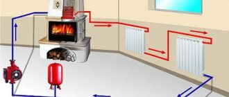
Supply and return in the heating system are separate systems designed to supply heated water to heating radiators and remove cooled liquid to the boiler or other heating equipment in order to further increase the temperature of the coolant. In what ways can you organize supply and return in modern conditions, read on.
Location of supply and return in the heating system
What is needed for this
To calculate the diameter of the pipe, as a rule, the following factors are taken into account:
- Total heat loss of the home.
- What power do heating radiators have separately in each room.
- The total length of the circuit pipes.
- How is the system wired?
To be able to calculate the diameter of the pipes, it is necessary to determine in advance the total heat loss, the power of the boiler equipment and batteries for each room. It is also important which method will be chosen for pipe routing. Having all these parameters in hand, a future calculation scheme is drawn up.
It is also important to remember some of the specific markings of different pipes. Thus, on polypropylene pipes for heating a private house, the outer diameter is indicated (the same applies to copper products). To calculate the internal parameter, the wall thickness is subtracted from this indicator. Steel and metal-plastic pipes are marked by their internal cross-section.
Selecting the appropriate pipe diameter for heating
It is almost impossible to accurately calculate the pipeline cross-section. For these purposes, several methods are used, with approximately the same final result. As you know, the main task of the system is to deliver the required amount of heat to the batteries in order to achieve maximum uniform heating of the heating device.
In forced circuits, a pipeline, coolant and circulation pump are used for these purposes. Using this set of devices, it is necessary to supply the required portion of the coolant in a fixed time. There are two ways to achieve this task - using smaller diameter pipes in combination with a higher speed of water movement, or using a system with a larger cross-section in which the traffic intensity will be lower.
Reasons for the popularity of the first option:
- Lower price for thinner pipes.
- Great ease of installation.
- In open areas such systems are less noticeable. If they are placed on the floor or walls, smaller installation spaces are required.
- Narrow pipes contain less liquid. This leads to a decrease in system inertia and fuel savings.
Thanks to a set of standard diameters and a fixed amount of heat transported through them, there is no need to carry out the same type of calculations. For these purposes, special tables have been compiled: they allow, having on hand data on the required amount of heat, water supply speed and operating temperature of the heating circuit, to calculate the required dimensions. To determine what pipe diameters there are for heating, you need to find the necessary table.
To calculate the diameter of heating pipes, the following formula is used: D = √354x(0.86x Q/∆t)/V, where D is the desired pipeline diameter (mm), ∆t° is the temperature delta (the difference between supply and return), Q is load for a given section of the system, kW – a certain amount of heat required to heat the room, V – coolant velocity (m/s).
Autonomous systems usually have a coolant movement speed of 0.2 - 1.5 m/s. As practical experience shows, the most optimal speed in such cases is 0.3 m/s - 0.7 m/s. When this indicator decreases, there is a real threat of air jams; when it increases, the coolant begins to make a lot of noise when moving.
There are tables to select the optimal value. They contain data for pipes made of different materials - metal, polypropylene, metal-plastic, copper. When determining the diameter of heating pipes, as a rule, the emphasis was placed on standard operating conditions with high and medium temperatures. Some examples will help you understand the essence of the procedure.
Air locks in heating
If the radiators are not heated in any of the rooms, it means that the air accumulated in the system is preventing the free movement of the coolant. An air lock can form due to many reasons, including the following:
- air enters when water is drained from the system and then refilled;
- Oxygen is released from water when heated;
- a faulty expansion tank creates a local area of low pressure;
- air is sucked into the system through connections with broken seals;
- air diffusion occurs through the surfaces of plastic pipes.
Air bubbles can accumulate either at the highest point of the piping system, or only in one of the radiators. Then the bottom of the battery will be hot and the top will remain cold. The presence of air in the pipes also provokes the appearance of unpleasant gurgling sounds. Most often, heating devices on the top floor of a building stop heating.
Due to air bubbles, not only does the heat supply through the piping system stop, but also corrosion of metal elements begins. The smooth operation of the circulation pump is also disrupted.
The use of simple technical devices will help get rid of the problem of clogging the heating system with air locks.
The most effective way to remove air from a closed heating system is to use automatic air vents. If they are mounted in several problem areas at once, then the air from each group of system elements will be released as it accumulates.
In addition to automatic ones, there are also manual air vents (Maevsky valve). Such a device is installed at the end of the radiator, located on the topmost floor. You can learn how to use it from the video presented here.
How to bleed air through the Mayevsky tap
Depending on how the heating system is designed, it may sometimes be necessary to bleed air through an expansion tank in the attic. The circulation pump can also help expel air pockets from the system.
Calculation of two-pipe systems
We are talking about a two-story house with a two-pipe heating system, two wings on each floor. Polypropylene pipes are used to construct the system. Operating mode – 80/60, temperature delta – 20 degrees. Heat loss level - 38 kW of thermal energy (first floor - 20 kW, second - 18 kW).
- First you need to decide which pipe to decorate the area between the boiler and the first branch. The entire volume of coolant is transported here, transferring heat to 38 kW. The reference data indicates two suitable parameters - 40 and 50 mm. It is more profitable to stay at a smaller diameter of 40 mm.
- At the point of flow separation, 20 kW is sent to the first floor, and 18 kW to the second. According to the reference book, the section is determined. In this case, for each direction the optimal diameter is 32 mm.
- In turn, each circuit includes two lines with an equal load. On the first floor, 10 kW is distributed in both directions (20 kW/2 = 10 kW), on the second floor - 9 kW (18 kW/2) = 9 kW). A suitable value for these branches would be 25mm. It is more reasonable to use this parameter until the load is reduced to 5 kW. After this, they switch to a diameter of 20 mm. The first floor is translated by 20 mm immediately behind the second radiator. The second floor usually passes after the third device. As practice shows, this transition is best carried out at a load of 3 kW.
In this way, the diameter of polypropylene pipes for a two-pipe system is calculated. There is no point in determining the dimensions of the return pipe: they are taken the same as for the supply. This procedure is simple: the main thing is to have everyone’s initial data. If you plan to use a different type of pipe to organize the system, you need to use data for a specific material of manufacture. Calculating the diameter of heating pipes with natural circulation is somewhat different.
Heating battery return is cold - device, causes, solutions
The efficient operation of the heating system determines how comfortable the temperature in the house will be during the cold season. Sometimes situations arise when hot water is supplied to the system, but the batteries remain cold. It is important to find the cause and eliminate it. To solve the problem, you need to know the design of the heating system and the reasons for cold return during hot supply.
The heating system consists of an expansion tank, batteries, and a heating boiler. All components are connected to each other in a circuit. A coolant liquid is poured into the system. The liquid used is water or antifreeze. If the installation is done correctly, the liquid is heated in the boiler and begins to rise through the pipes. When heated, the liquid increases in volume, the excess enters the expansion tank.
Heating system design with expansion tank
Since the heating system is completely filled with liquid, the hot coolant displaces the cold coolant, which returns to the boiler, where it is heated. Gradually, the temperature of the coolant increases to the required temperature, heating the radiators. Liquid circulation can be natural, called gravitational, or forced, using a pump.
The return is a coolant that, having passed through all the heating devices included in the circuit, gives up its heat and, cooled, enters the boiler again for the next heating.
Batteries can be connected in three ways:
- 1. Bottom connection.
- 2. Diagonal connection.
- 3. Lateral connection.
In the first method, the coolant is supplied and the return is discharged at the bottom of the battery. This method is advisable to use when the pipeline is located under the floor or baseboards. With a diagonal connection, the coolant is supplied from above, the return is discharged from the opposite side from below. This connection is best used for batteries with a large number of sections. The most popular method is side connection. The hot liquid is connected from above, the return is discharged from the bottom of the radiator on the same side where the coolant is supplied.
Return in the heating system
Heating systems differ in the way pipes are laid. They can be laid in one-pipe or two-pipe ways. The most popular is the single-pipe wiring diagram. Most often it is installed in multi-storey buildings. It has the following advantages:
- a small number of pipes;
- low cost;
- ease of installation;
- serial connection of radiators does not require the organization of a separate riser for liquid drainage.
Disadvantages include the inability to adjust the intensity and heating for a separate radiator, and a decrease in the temperature of the coolant as it moves away from the heating boiler. To increase the efficiency of single-pipe distribution, circular pumps are installed.
To organize individual heating, a two-pipe pipe layout is used. Hot feed is carried out through one pipe. In the second, cooled water or antifreeze flows back into the boiler. This scheme makes it possible to connect radiators in parallel, ensuring uniform heating of all devices. In addition, the two-pipe circuit allows you to regulate the heating temperature of each heating device separately. The disadvantage is the complexity of installation and the high consumption of materials.
Sometimes, with a hot supply, the return of the heating battery still remains cold. There are several main reasons for this:
- installation was performed incorrectly;
- the system or one of the risers of a separate radiator is airborne;
- insufficient fluid flow;
- the cross-section of the pipe through which the coolant is supplied has decreased;
- The heating circuit is dirty.
Adjusting the check valve in the heating system
Cold return is a serious problem that must be eliminated. It entails many unpleasant consequences: the temperature in the room does not reach the desired level, the efficiency of radiators decreases, and there is no way to correct the situation with additional devices. As a result, the heating system does not work as it should.
The main trouble with cold return is the large temperature difference that occurs between the supply and return temperatures. In this case, condensation appears on the walls of the boiler, reacting with carbon dioxide, which is released during fuel combustion. As a result, acid is formed, which corrodes the walls of the boiler and shortens its service life.
If you find that the return is too cold, you should take a number of steps to find the causes and troubleshoot problems. First of all, you need to check that the connection is correct. If the connection is not made correctly, the down pipe will be hot when it should be slightly warm. The pipes should be connected according to the diagram.
Sometimes it may be necessary to dismantle the control valve to increase the cross-section
To avoid air pockets that impede the flow of coolant, it is necessary to provide for the installation of a Mayevsky valve or bleeder for air removal. Before bleeding the air, you need to turn off the supply, open the tap and let out the air. Then the tap is turned off and the heating valves open.
Often the cause of cold return is the control valve: the cross-section is narrowed. In this case, the tap must be dismantled and the cross-section increased using a special tool. But it is better to buy a new faucet and replace it.
The reason may be clogged pipes. You need to check them for passability, remove dirt and deposits, and clean them well. If passability cannot be restored, the clogged areas should be replaced with new ones.
If the coolant flow rate is insufficient, you need to check whether there is a circulation pump and whether it meets the power requirements. If it is missing, it is advisable to install it, and if there is a lack of power, replace or upgrade it.
Knowing the reasons why heating may not work efficiently, you can independently identify and eliminate malfunctions. Comfort in the house during the cold season depends on the quality of heating. If you carry out the installation and inspection of the heating system yourself, you can save on hiring third-party labor.
obustroen.ru
Calculation of a single-pipe forced-type system
The principle applied is the same as in the previous case, but the algorithm of actions changes. For example, you can take the calculation of the internal diameter of a simple single-pipe heating system in a one-story house. The circuit has six radiators connected in series.
The procedure for calculating the diameter of the heating pipeline based on thermal power:
- The boiler transfers 15 kW of heat to the beginning of the system. According to the reference data, this section can be equipped with 25 mm and 20 mm pipes. As in the first example, it is better to choose 20 mm.
- Inside the first battery, the thermal load is reduced to 12 kW. This does not affect the cross-section of the outgoing pipe in any way: it remains the same value of 20 mm.
- The third radiator reduces the load to 10.5 kW. In this case, the cross-section remains the same - the same 20 mm.
- The transition to a smaller diameter of 15 mm occurs after the fourth battery, as the load is reduced to 8.5 kW.
- The coolant is transported to the fifth device through a 15 mm pipe, and after it there is a transition to 12 mm.
At first glance, it may seem that calculating pipe diameters for a heating system is easy and simple. Indeed, when polypropylene or metal-plastic products are used to organize the circuit, difficulties usually do not arise. This is explained by their low thermal conductivity and small heat leaks through the walls (they can be ignored). The situation is completely different with metal products. If the steel, copper or stainless steel pipeline is of considerable length, quite a lot of thermal energy will flow through its surface.
Consequences of problems with return flow
This article has already mentioned that problems with the return flow must be corrected as soon as possible. Now we will provide you with a list of reasons that explain the consequences of slowness in this matter.
- Poor battery heating. It is logical that in this situation the quality of heating will suffer first. The room will not warm up properly and the rooms will have a low temperature.
- Dissonance between temperatures, that is, a very large difference between the temperature at which water is supplied and the temperature at which it returns back to the boiler. This leads to the formation of condensation inside the boiler, which, entering into a chemical reaction with the released carbon dioxide, turns into acid. This acid will destroy the inner walls of the boiler, which will eventually lead to its failure.
How to calculate metal pipes
Large heating systems equipped with metal pipes require taking into account heat loss through the walls. Although on average these figures are quite low, on very long branches the total value of lost energy is quite high. Often because of this, the last batteries in the heating circuit do not heat up well enough. There is only one reason - the diameter of the pipes was chosen incorrectly.
An example would be the determination of losses of a 40 mm steel pipe with a wall thickness of 1.4 mm. For the calculation, the formula is used q = kх3.14х(tв-tп), where q is the heat loss of a meter of pipe, k is the linear heat transfer coefficient (in this case it corresponds to 0.272 W*m/s), tв is the temperature of the water inside (+80 degrees), tп – air temperature in the room (+22 degrees).
To get the result, you need to substitute the required values into the formula:
q = 0.272x3.15x(80-22) = 49 W/s
The picture that emerges is that every meter of pipe loses heat in an amount of almost 50 W. On very long pipelines, the total losses can be simply catastrophic. In this case, the volume of leaks directly depends on the cross-section of the circuit. To take into account such losses, a similar indicator on the pipeline must be added to the indicator for reducing the thermal load on the battery. Determination of the optimal pipeline diameter is carried out taking into account the total value of leaks.
Typically, in autonomous heating systems, these indicators are not critical. In addition, during the procedure for determining heat loss and boiler power, the data obtained is usually rounded up. Thanks to this, a safety stock is created, freeing from complex calculations.
Finding relevant data
As for finding the optimal reference data, almost all websites of manufacturers of heating system components provide this information. In cases where suitable values have not been found, there is a special system for selecting diameters. This technique is based on calculations, and not on average patterns based on processing data on a huge number of heating systems. Calculation of the coolant by pipe cross-section was developed by plumbers with practical experience in installation work, and is used for arranging small circuits inside homes.
In the vast majority of cases, heating boilers are equipped with two sizes of supply and return pipes: ¾ and ½ inches. This size is taken as the basis for wiring up to the first branch. In the future, each new branch serves as a reason to reduce the diameter by one position. This method allows you to calculate the cross-section of pipes in an apartment. We are talking about small systems with 3-8 radiators. Typically such circuits consist of two or three lines with 1-2 batteries. Small private cottages can be calculated in a similar way. If there are two or more floors, you have to use reference data.
Options for organizing the supply and removal of coolant to radiators
When installing heating systems, two main wirings are used: with one or two pipes; a combined supply of free-standing heat exchangers is often practiced. In many cases, the connection points for radiators are their two pipes located on the sides; modifications with two lower outlets are similarly connected when installed using special N-shaped bottom connection units (binoculars).
Fig. 5 Top supply in an apartment building - traffic diagram
Single pipe system
This wiring has become widespread in public utilities and everyday life due to its following advantages and features:
- The option with one pipe is the most profitable from a financial point of view, allowing you to save materials twice as much as compared to a two-pipe one.
- In addition to saving materials, the complexity of installation is reduced and, accordingly, the cost of arranging a single-pipe distribution is reduced - fewer grooves are made in the walls, a relatively small number of different types of fittings are purchased: bends, tees, shut-off and control valves, couplings, the work on assembling the pipeline is accelerated by soldering, press or compression fittings.
- In a line with one pipe, the coolant moves sequentially along the entire chain of radiators, with the first one, closest to the heating boiler or heating network, having the highest heat transfer, and the last one being the coldest.
Equation method
Although pipes made of different materials are marked with different values (internal or external), in some cases they can be equated. This applies to situations where it is not possible to find data on a specific pipe: in such a situation, you can use information on a similar cross-section of a product made of a different material.
Let's say you need to calculate what diameter of a metal-plastic pipe is needed for heating, but the necessary information on this material has not been found. As an alternative, a table of coolant speed in the heating system for polypropylene products is used. Using the appropriate dimensions, the appropriate parameters for the metal-plastic pipe are selected. In this case, it is impossible to avoid inaccuracies, but in forced-type circuits they are not critical.
The battery does not heat up
If one or more radiators do not heat or heat poorly, then the first thing you need to do is check if there is air in them using air vents. If water flows from the drains, but the radiator still does not heat, then you need to make sure that both taps of this radiator are open (such inattention can often occur). The next step is to check if the radiator is clogged. To do this, other heating radiators that heat and are on the same branch as the non-working one must be shut off so that all the water flows through this radiator. If it starts to warm up, it means it is not clogged. In this case, it is necessary to hydraulically level the branch. In simple terms, it is necessary to cover the remaining radiators on the branch so that the one who is not working gets more. You need to be prepared that leveling will take more than one day, because the heating system may be slow to respond to changes in settings. If the taps in front of the radiator are completely open, and it is cold, then it is clogged (extremely low probability). Basically, the last radiators on the branch may not heat . But this can always be eliminated by hydraulic leveling. If someone tells you that “it’s not pumping there” or “the pump’s power is insufficient,” don’t rush to believe and touch the pump or pipes. In order to prevent the pump from pumping too much, you need to try very hard when installing the heating system. If one or more of the last radiators does not heat up even after working with the taps, then there may be an air lock in the pipes (see circulation disturbance in the heating system).
Conclusion
Using a not very complex and branched scheme to organize the heating of your home, you can calculate the optimal pipeline diameter on your own. To do this, you need to arm yourself with information about the heat loss of your home and the power of each battery. Next, using special tables and reference books, the optimal value of the pipe cross-section is selected, which can ensure the transportation of the required volume of thermal energy to each of the rooms.
If complex schemes with many elements are used, then it is advisable to invite a professional plumber to calculate them. If you have confidence in your own abilities, it is still recommended to consult with a specialist. There are cases when, due to mistakes made, it is necessary to undertake an expensive reconstruction of the entire circuit.
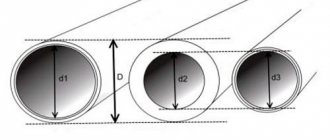
The diameter of the heating pipes depends on the volume of coolant that will pass through them. Obviously, on the main supply pipeline coming from the heating boiler, the diameter will be larger, on the branch with three radiators it will be even smaller, and on the final radiator it will be the smallest. Accordingly, the diameter of the pipe will depend on the total thermal power of the radiators that feed the pipeline.
In addition, the diameter of the pipeline depends on the speed of movement of the coolant in the system and on the supply/return temperature difference. The higher this difference, the smaller the pipeline diameter required. The standard temperature difference is 20°C. In more comfortable systems, this difference is less – 10°C.
A heating system with a circulation pump is characterized by a high coolant speed, while a system with natural circulation has a low speed, so this must be taken into account when selecting heating pipes. You should not factor in too high a speed of water movement in the pipes when calculating pipelines, because... this will create various unpleasant noises and babbling in the pipes. If the speed is too low, there is a risk of air locks forming in the system. The speed of movement in the pipes should be in the range of 0.4 - 0.6 m/s. A gravity-flow system is characterized by a significantly lower coolant velocity, so the diameter of the pipes must be chosen larger.
Therefore, below we provide tables for selecting pipe diameters for various systems with the specified parameters. The table uses the selection of pipe diameters from various materials. VGP steel pipes are designated by the internal diameter, while polypropylene, metal-plastic and cross-linked polyethylene pipes are designated by the outer diameter. This is taken into account in the table for selecting pipeline diameters.
How important is the speed of water circulation?
This is one of the most important questions. I answer it immediately and very definitely. Water speed is very important. If the water speed is low, you will freeze and waste extra fuel. Although this sounds like a cliche, it is actually not completely cliche. I hope you understand this now.
Why should water go into a branch?
This is the question that tormented me when I was designing a heating system for myself. I really can't figure out what causes water coming through a straight pipe to enter a 90 degree branch of that pipe. If you understand this, you are happy people! But I don't understand. I put myself in the place of water. There is a wide pipe in front of me. I'm moving along it in a straight direction. Why on earth would I, the water that is, suddenly be distracted from this movement and go across its current into a thinner pipe, and even at a right angle to my original direction of movement? In order to go into a more subtle branch, I need to at least notice it. Then I have to brake to turn. Then I need to slow down even more, because in a narrower pipe I cannot move at the same speed. Well, okay, if I had a special lane for turning (like on a highway), I would have seen the sign in advance, changed lanes (smoothly) and just as smoothly turned onto the branch. But we don’t give the water such conditions, and for some reason we expect it to willingly go into a perpendicular pipe. No! I absolutely don’t understand!
Single pipe heating
What do I think could cause water to go into the branch?
I think - only an obstacle in a straight pipe. Then this obstacle will create some kind of excess pressure, and due to this pressure, the water will look for other passage ways and go into the branch. What could be such an obstacle?
- A sharp turn on the main road.
- Friction of water on the inner surface of the main pipe.
- Air, sand, rust accumulated in the line.
- Water with a different density, for example, is colder.
- (Attention!!!) High water speed in the system!
It seems to me that the higher the water speed, the higher the friction and the greater the obstacle any roughness in the line or turn will be. Speed cannot increase indefinitely. The speed is balanced by friction and as a result the water pressure increases.
conclusions
If the supply line is straight, if its inner surface is smooth and if the water speed is low, then, apparently, nothing will force the water to enter the radiator. He will always be cold.
If the excess pressure during water movement is minimal, then the speed of water in the radiator and its temperature will be exactly the same minimum. For example, if a branch gradually cools over 30 cm from the fork, then this means that water flows into this branch, but its speed is so tiny that it manages to cool while it passes these same 30 cm. You can estimate the speed yourself in this case.
Application example: two-pipe system with circulation pump, total power 18 kW.
The wiring is made with a polypropylene pipe, symbol - PP.
As we can see from the diagram, first a polypropylene pipe with a diameter of 40 mm comes out of the boiler, its internal clearance is 25 mm, which corresponds to a metal VGP pipe of 1 inch (25 mm). Next comes the outlet for the boiler (4 kW) and heated floors (2 kW) of two PP pipes with a diameter of 16 mm. After this, part of the coolant separated, so there is no need for such a thick pipe. A thinner pipe will be used for heating the 1st and 2nd floors - 32mm, it will go to the first tee. At the tee, a branch is separated to the 1st floor, with a diameter of 25 mm, and to the 2nd floor, also with a diameter of 25 mm. A polypropylene pipe with a diameter of 16 mm is already suitable for the final radiators. And on the last 3 radiators the supply pipe is also narrowed to 16mm.
In a one-pipe system, unlike a two-pipe system, the entire coolant of the system is supplied through one pipeline. Therefore, in such a system, the entire pipeline (after branching the pipe to the boiler and heated floor) will have a diameter of 32 mm, and 16 mm pipes will be suitable for individual radiators from the main pipeline.
In the article we will consider systems with forced circulation. In them, the movement of the coolant is ensured by a constantly running circulation pump. When choosing the diameter of heating pipes, it is assumed that their main task is to ensure the delivery of the required amount of heat to heating devices - radiators or registers. For the calculation you will need the following data:
- General heat loss of a house or apartment.
- The power of heating devices (radiators) in each room.
- Pipeline length.
- Method of wiring the system (one-pipe, two-pipe, with forced or natural circulation).
That is, before you start calculating the diameters of the pipes, you first calculate the total heat loss, determine the power of the boiler and calculate the power of the radiators for each room. You will also need to decide on the wiring method. Using these data, you draw up a diagram and then just start calculating.
To determine the diameter of the heating pipes, you will need a diagram with the thermal load values assigned to each element.
What else do you need to pay attention to? The fact is that the outer diameter of polypropylene and copper pipes is marked, and the inner diameter is calculated (subtract the wall thickness). For steel and metal-plastic ones, the internal size is indicated when marking. So don't forget this little thing.
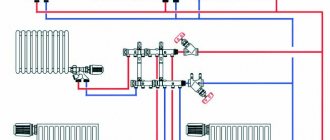
Connection diagrams for boilers, radiators, piping in home heating
You can make a heating system for your home yourself if you have the skills to do plumbing and construction work. In other words, you need to be able to solder pipes, cut them, connect them, and also tighten nuts, know the purpose and technical characteristics of the equipment used, have an understanding of hydraulics and heating engineering, and much more...
Then, using standard proven schemes and solutions, you can create a heating system for a small house only with your own hands.
But if you don’t have the skills to do the work, you will have to watch how specialists make the heating system. At the same time, it is also highly advisable to familiarize yourself with the basic rules for creating a system, equipment layout diagrams, etc., in order to monitor the progress of work and eliminate errors in a timely manner, if any are made.
Below are some nuances of creating a heating system in a private home, which you should always pay attention to first. Let's start with connecting the boiler, since many mistakes are often made in the boiler room.
Connecting a wall-mounted boiler
Wall-mounted boilers are usually automated; they contain two important elements of the heating system:
- safety group, which usually consists of an air valve, pressure gauge, emergency overpressure valve;
- circulation pump, which ensures the movement of fluid in the heating system;
Therefore, connecting a wall-mounted boiler is the simplest; it should be done according to the following scheme (we consider the direction “from the boiler”):
Supply: – tap with American connection for connecting the boiler; - transition fitting for pipes - American.
The tap is required and is placed immediately in front of the boiler so that the boiler can be serviced without draining the system.
Return: - tap with American connection for connecting the boiler; — dirt filter; - tap; — a tee with an expansion tank, a shut-off valve, a drain and fill valve for the system. - transition fitting for pipes - American.
A dirt filter is a mandatory element of any heating system. It is installed with the sump facing down, or, in extreme cases, horizontally. Dirt from the system will accumulate in the filter and is periodically removed from the sump. When installing, you must observe the direction relative to the stream.
The taps near the filter are required; only by closing both taps can you service and clean the filter.
Next, let's look at the piping of a floor-standing boiler. It is more complicated, since a floor-standing boiler does not have a safety group and a pump. Therefore, they are installed independently, like elements of a boiler room.
Safety group, circulation pump, expansion tank
For the safety group, it is better to purchase a special tee and mount the devices listed above on it. It is important to select devices in accordance with the parameters of the heating system, usually the maximum pressure is 4 MPa, the operating pressure is 1.5 - 2.0 Atm.
The pump is purchased according to the characteristics of the system. For an ordinary small house (up to 150 sq. m.), a circulation pump with a pressure of up to 4 m (0.4 atm) will always be sufficient for the heating system (often for radiators up to 250 sq. m.)
Accordingly, the pump is marked 25 - 40, where the first number indicates the thread diameter of the connection pipes, in this case 25 mm - 1 inch, but it can be 32 mm or more. The second number 40 is a designation of the pressure created - up to 0.4 atm, and therefore, indirectly, the power of the pump.
Each circulation pump has a rotation speed adjustment in at least 3 positions, which will determine the volume of liquid pumped and the actual power consumption.
In the first adjustment position, the circulation pump 25-40 will consume no more than 30 W of electricity. More often, for a properly designed heating system in an insulated house up to 150 sq. m. There will be enough thermal energy that can be supplied by this pump at first speed.
An often repeated mistake when creating a heating system is installing overly powerful pumps, despite the fact that they cost many times more and consume more electricity. Where a pump of 25 - 40 m is optimal (in most small houses), pumps of 25 - 60, and even 25 - 80 and more powerful are installed.
The volume of the expansion tank can be selected using a simplified formula - 1/10 of the volume of coolant in the system. A little more is better, but not less. For example, if the system has 200 liters, then it is better to install a 35 liter expansion tank but not less than 20 liters.
Connecting a floor-standing non-automated boiler
Let's look at a diagram of how a floor-standing boiler that is not equipped with automation should be connected. (In the direction from the boiler.)
How to choose the diameter of a heating pipe
It will not be possible to calculate exactly what cross-section of pipes you need. You will have to choose from several options. And all because the same effect can be achieved in different ways.
Let me explain. It is important for us to deliver the right amount of heat to the radiators and at the same time achieve uniform heating of the radiators. In systems with forced circulation, we do this using pipes, coolant and a pump. In principle, all we need is to “drive” a certain amount of coolant over a certain period of time. There are two options: install pipes of a smaller diameter and supply coolant at a higher speed, or make a system of a larger cross-section, but with less traffic. Usually the first option is chosen. And that's why:
- the cost of products with a smaller diameter is lower;
- they are easier to work with;
- when laid open, they do not attract so much attention, and when laid in the floor or walls, smaller grooves are required;
- with a small diameter, there is less coolant in the system, which reduces its inertia and leads to fuel savings.
Calculation of the diameter of copper heating pipes depending on the power of the radiators
Since there is a certain set of diameters and a certain amount of heat that needs to be delivered through them, it is unreasonable to calculate the same thing every time. Therefore, special tables have been developed, according to which, depending on the required amount of heat, the speed of movement of the coolant and the temperature indicators of the system, the possible size is determined. That is, to determine the cross-section of pipes in the heating system, find the required table and select the appropriate cross-section from it.
The diameter of the heating pipes was calculated using the following formula (you can calculate it if you wish). Then the calculated values were recorded in a table.
Formula for calculating the diameter of a heating pipe
D - required pipeline diameter, mm ∆t° - temperature delta (difference between supply and return), °C Q - load on a given section of the system, kW - determined amount of heat required to heat the room V - coolant velocity, m/s - selected from a certain range.
In individual heating systems, the coolant movement speed can be from 0.2 m/s to 1.5 m/s. Based on operating experience, it is known that the optimal speed is in the range of 0.3 m/s - 0.7 m/s. If the coolant moves more slowly, air jams occur; if it moves faster, the noise level increases significantly. The optimal speed range is selected in the table. The tables are designed for different types of pipes: metal, polypropylene, metal-plastic, copper. The values are calculated for standard operating modes: high and medium temperatures. To make the selection process more clear, let’s look at specific examples.
Penalty for excess return flow Blog of a heating engineer
Hello, dear readers of the blog teplosniks.ru! On my blog I previously wrote about overheating of the heating return. The most unpleasant thing in such a situation is when you are given a specific bill for overheating in the return pipeline. No one wants to part with money, especially when the volume of heat consumption is calculated in the form of penalties. You have to pay the meter and more. So, how exactly does the energy supply organization calculate the fine?
The first point determines the contractual flow of network water through the heating unit. It is determined by the formula:
where Qdog is the heat load for heating under the contract (this figure must be in the contract, look). Let's take a specific figure of 0.332 Gcal/hour.
C—heat capacity of water, kcal/kg °C
t1 — supply temperature according to schedule, °C
t2 — return temperature according to schedule, °C
We substitute specific numbers. Usually the temperature graph is 150/70 °C (but it can also be 130/70 °C and 105/70 °C, etc.). In our case t1 = 150°С; t2 = 70°C. The heat capacity of water can be taken to be unity, C = 1. In fact, the heat capacity will be slightly different from unity, but we don’t need such super-precision. So, we calculate the figure, the consumption of network water, which should be according to the contract.
Gdog = 0.332*1000 /(150-70)*1 = 4.15 t/hour.
We have the water consumption according to the contractual load that must pass through your heating unit. The actual consumption (according to the meter printout) should not exceed the contractual one. If it exceeds, it means you are overheating. In order to count further, you need a printout from the heat meter. The printout looks like this.
This is a printout from the KM-5 heat meter. I give it only as an example. Your metering device can be any other one, not necessarily KM-5. But the essence of the matter does not change, in any printout, from any heat meter, the main figures are heat consumption Q in Gcal and temperatures t1 and t2, in °C. Using this very printout, we need to calculate the actual water flow through the heating unit. It is calculated according to the same formula:
Gfact = Qfact*1000 ⁄(t1fact-t2fact)*C.
We look at your printout of the supply and return temperatures t1 and t2. Let t1 = 73.1 °C, t2 = 49.5 °C. We also look at the amount of heat Qfact from the printout, let this figure be 101.4 Gcal. We divide the number of Gcal per month by the number of hours in the month, 101.4 Gcal per 720 hours, we get 0.141 Gcal/hour. Let's count further:
Gfact = 0.141*1000 ⁄(73.1-49.5)*1 = 5.97 t/hour.
At t1 = 73.1 °C, return according to the schedule is 43.8 °C. In fact, here we have 49.5 °C. Overheating 49.5-43.8 = 5.7 °C. If expressed as a percentage, then it was overheated by 13.01%. Accordingly, such overheating gave us an excess of actual consumption over the calculated G exceeded. = 5.97-4.15 = 1.82 t/hour. Now you can calculate specifically how many Gcal penalties the heat supply organization will charge you.
It is calculated by the formula:
Qfine = Gexceed*С*(t2actual-t2 permissible excess according to schedule)*number of hours per month*0.001.
We calculate the permissible excess of t2 according to the 5% schedule as follows: take t2, which should be at t1 = 73.1 °C, according to the schedule - 43.8 °C and multiply by 1.05 we get 45.99 °C. Let's calculate how much we will be charged for overheating:
Calculation for a two-pipe system
There is a two-story house with a two-pipe heating system, two wings on each floor. Polypropylene products will be used, operating mode 80/60 with a temperature delta of 20 °C. The heat loss of the house is 38 kW of thermal energy. The first floor has 20 kW, the second 18 kW. The diagram is shown below.
Two-pipe heating scheme for a two-story house. Right wing (click to enlarge)
Two-pipe heating scheme for a two-story house. Left wing (click to enlarge)
On the right is a table from which we will determine the diameter. The pinkish area is the zone of optimal coolant movement speed.
Table for calculating the diameter of polypropylene heating pipes. Operating mode 80/60 with a temperature delta of 20°C (click to enlarge)
- We determine which pipe needs to be used in the area from the boiler to the first branch. The entire coolant passes through this section, therefore the entire heat volume of 38 kW passes through. In the table we find the corresponding line, follow it to the pink-tinted area and go up. We see that two diameters are suitable: 40 mm, 50 mm. For obvious reasons, we choose the smaller one - 40 mm.
- Let's look at the diagram again. Where the flow is divided, 20 kW goes to the 1st floor, 18 kW goes to the 2nd floor. In the table we find the corresponding lines and determine the cross-section of the pipes. It turns out that we are dividing both branches with a diameter of 32 mm.
- Each of the circuits is divided into two branches with equal load. On the first floor there is 10 kW each to the right and left (20 kW/2=10 kW), on the second floor 9 kW each (18 kW/2)=9 kW). Using the table, we find the corresponding values for these areas: 25 mm. This size is continued to be used until the heat load drops to 5 kW (as seen in the table). Next comes a section of 20 mm. On the first floor we go 20 mm after the second radiator (look at the load), on the second - after the third. At this point there is one amendment made by accumulated experience - it is better to switch to 20 mm at a load of 3 kW.
What is heating system return?
Knowing the basic principles of a heating device, it is quite simple to answer the question of what a return is - it is a pipeline through which the medium leaving the heat transfer devices is directed to the boiler equipment for subsequent heating.
Almost any heating device has at least two built-in connection pipes, and with a two-pipe system, the return and supply circuits have a clear distinction (separate collectors). With a single-pipe connection method, the devices are connected in series to each other, so the supply pipe is connected to the first battery in the circuit from the boiler, and the return pipe is the pipe coming out of the last one. When using the popular “Leningrad”, the return should be considered the pipeline section after all the heaters in the circuit.
Rice. 2 Multi-circuit heating scheme for a cottage - example (the return of the heating system is marked in blue)
Determination of pipe diameter for a single-pipe system with forced circulation
The principle remains the same, the methodology changes. Let's use another table to determine the diameter of pipes with a different principle for entering data. In it, the optimal zone of coolant movement speeds is colored blue, the power values are not in the side column, but are entered in the field. That's why the process itself is a little different.
Table for calculating the diameter of heating pipes
Using this table, we calculate the internal diameter of the pipes for a simple one-pipe heating circuit for one floor and six radiators connected in series. Let's start the calculation:
- 15 kW is supplied to the system input from the boiler. We find values close to 15 kW in the optimal speed zone (blue). There are two of them: in a line measuring 25 mm and 20 mm. For obvious reasons, we choose 20 mm.
- On the first radiator, the thermal load is reduced to 12 kW. We find this value in the table. It turns out that it goes further from it of the same size - 20 mm.
- On the third radiator the load is already 10.5 kW. We determine the cross section - still the same 20 mm.
- Judging by the table, the fourth radiator is already 15 mm: 10.5 kW-2 kW = 8.5 kW.
- On the fifth there is another 15mm, and after that you can already put 12mm.
Scheme of a one-pipe system with six radiators
Please note again that the table above defines internal diameters. Using them you can then find the markings of pipes made of the desired material.
It seems that there should be no problems with how to calculate the diameter of the heating pipe. Everything is quite clear. But this is true for polypropylene and metal-plastic products - their thermal conductivity is low and losses through the walls are insignificant, therefore they are not taken into account when calculating. Another thing is metals - steel, stainless steel and aluminum. If the length of the pipeline is significant, then the losses through their surface will be significant.
Features of calculating the cross-section of metal pipes
For large heating systems with metal pipes, heat loss through the walls must be taken into account. The losses are not that great, but over a long distance they can lead to the fact that the temperature on the last radiators will be very low due to the wrong choice of diameter.
Let's calculate the losses for a 40 mm steel pipe with a wall thickness of 1.4 mm. Losses are calculated using the formula:
q = k*3.14*(tв-tп)
q is the heat loss per meter of pipe,
k is the linear heat transfer coefficient (for this pipe it is 0.272 W*m/s);
tw — water temperature in the pipe — 80°C;
tп — room air temperature — 22°С.
Substituting the values we get:
q = 0.272*3.15*(80-22)=49 W/s
It turns out that almost 50 W of heat is lost per meter. If the length is significant, this can become critical. It is clear that the larger the cross-section, the greater the losses will be. If you need to take these losses into account, then when calculating losses, add losses in the pipeline to reduce the thermal load on the radiator, and then, using the total value, find the required diameter.
Determining the diameter of heating system pipes is not an easy task
But for individual heating systems these values are usually not critical. Moreover, when calculating heat loss and equipment power, the calculated values are most often rounded upward. This gives a certain margin, which allows you not to make such complex calculations.
An important question: where to get tables? Almost all manufacturers' websites have such tables. You can read it directly from the site, or you can download it for yourself. But what to do if you still haven’t found the necessary tables for the calculation. You can use the diameter selection system described below, or you can do it differently.
Despite the fact that different values (internal or external) are indicated when marking different pipes, they can be equated with a certain error. Using the table below you can find the type and marking for a known internal diameter. You can immediately find a corresponding pipe size made of a different material. For example, you need to calculate the diameter of metal-plastic heating pipes. You did not find a table for MP. But there is one for polypropylene. Select sizes for PPR, and then use this table to find analogues in MP. Naturally, there will be an error, but for systems with forced circulation it is acceptable.
Correspondence table for different types of pipes (click to enlarge size)
Using this table, you can easily determine the internal diameters of the heating system pipes and their markings.
Selection of pipe diameter for heating
This method is not based on calculations, but on a pattern that can be traced when analyzing a fairly large number of heating systems. This rule was developed by installers and is used by them on small systems for private houses and apartments.
The diameter of the pipes can be simply selected following a certain rule (click to enlarge size)
Most heating boilers have two sizes of supply and return pipes: ¾ and ½ inches. It is with this pipe that the pipe is routed until the first branch, and then at each branch the size is reduced by one step. In this way you can determine the diameter of the heating pipes in the apartment. Systems are usually small - from three to eight radiators in the system, maximum - two or three branches with one or two radiators on each. For such a system, the proposed method is an excellent choice. The situation is practically the same for small private houses. But if there are already two floors and a more extensive system, then you have to count and work with tables.