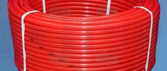
Water heated floors are gaining popularity every year. The most important part of this design is the pipes. Today, the construction market offers a large number of pipes for heating water floor systems from different manufacturers. Therefore, in all this diversity it is difficult to choose the right contour for a warm floor.
This article will reveal all the pros and cons of each type. This will help you understand the features of the products and purchase a high-quality pipe at an affordable price for laying a heated floor in a “pie” in a private house or apartment.
Choosing a diameter based on pipe material
The question of what pipe diameter to choose for a heated floor can be resolved by taking into account the amount of heat transfer from the materials used to produce this product.
To install heated floors, use:
- metal-plastic pipes;
- polyethylene products, including those made from cross-linked polyethylene;
- copper products;
- stainless steel corrugated pipes.
Metal-plastic products
When choosing pipes for a heated floor, preference is given to metal-plastic, you should know that this material has a complex structure. Inside the products there is an aluminum tube, which is lined with polyethylene in several layers.
Such products are characterized by a high degree of heat transfer, so when constructing a system, a 16 mm diameter is suitable. When choosing pipes for a warm water floor in favor of metal-plastic products, you must remember that aluminum and polyethylene have different expansion coefficients, and this circumstance can affect the service life of the heating structure.
Cross-linked polyethylene
Thanks to modern technologies, such a seemingly fragile material as polyethylene has been made suitable for the production of pipes.
In conventional polyethylene, hydrocarbon molecules are not connected to each other in any way, but in a new material (PEX, or cross-linked polyethylene), hydrocarbon molecules are connected through the interaction of hydrogen and carbon atoms. Additional processing under high pressure makes the material even more durable. The production of cross-linked pipes for heated floors has become widespread only recently, although the technology itself was developed about 40 years ago. The new material has characteristics that are not inherent in its predecessor. In particular, cross-linked propylene for heated floors is characterized by high mechanical strength, that is, it is not afraid of scratches and does not wear out, and is resistant to temperature fluctuations. Mainly, the properties of the material are affected by the technique and degree of crosslinking.
When deciding which cross-linked polyethylene to choose for a heated floor, you should pay attention to a material with a degree of cross-linking of 65-80%. This indicator will affect the strength and durability of the products, but at the same time, their price will also increase
True, unnecessary costs at the installation stage will pay off in the future due to the reliability and long service life of the pipes.
With a low degree of cross-linking, polyethylene will quickly lose its original qualities, crack under the influence of external factors and require replacement. However, no less important is the way in which molecular bonds are created.
There are 4 types of crosslinking:
- peroxide;
- silane;
- nitric;
- radiation.
When choosing which pipe to make a heated floor from, take a closer look at its markings. The highest quality is PEX-a, although it is the most expensive. But pipes marked PEX-b, cross-linked using the silane method, are in high demand. They have a relatively low price along with good performance properties.
This material also has other advantages, in particular:
- Ability to fully operate at temperatures from 0 ℃ to 95 ℃.
- Cross-linked polyethylene begins to melt only at a temperature of 150 ℃, and it burns at 400 ℃, so it can be successfully used in underfloor heating systems.
- Pipes made of cross-linked polyethylene are characterized by the so-called “molecular memory”, that is, after increasing the temperature of the material, any possible deformations are smoothed out, and the products themselves return to their original shape.
- The good resistance of cross-linked polyethylene products to pressure drops in heating systems is another argument in their favor when deciding which pipe to use for a heated floor. Depending on the characteristics, such pipes can maintain a pressure of 4-10 atmospheres.
- PEX pipes are characterized by good ductility, so even if they are repeatedly bent in the same place, they do not break.
- Cross-linked polyethylene is biologically and chemically resistant. This means that bacteria and fungus do not multiply on the inner surface of the pipes, and the material itself does not react with an aggressive environment and does not corrode.
- The chemical composition of cross-linked polyethylene is absolutely safe. It does not release toxins, and at the moment of combustion it breaks down into carbon dioxide and water.
Recommended operating temperatures for cross-linked polyethylene pipes are 0-95 ℃, but for a short time the range can expand to -50 - +150 ℃, and the material will not burst and will remain durable. However, such increased loads lead to a reduction in the service life of the material.
Some users confuse heat-resistant polyethylene pipes with PEX products. It is not correct. Indeed, heat-resistant polyethylene is capable of functioning at high temperatures, but in all other qualities it lags far behind cross-linked polyethylene. PEX pipes can resist aggressive external factors much longer, but their price is higher. And their installation does not require complex equipment and is accessible to every consumer.
So, if you are in doubt about what kind of pipes are needed for a heated floor, you can safely choose products made from cross-linked polyethylene. Moreover, their characteristics make it possible to use such pipes even for radiator heating and hot water supply. The only limitation is to minimize the exposure of the material to direct sunlight, although this is not relevant for heated floors.
In order not to damage the outer anti-diffusion layer on the pipes, their transportation and installation should be carried out very carefully. Violation of the integrity of the protective coating will lead to a decrease in the durability of the pipe due to oxygen entering the material structure.
Plastic pipe products
Polypropylene pipes have a lower heat transfer rate, and in addition, when they are bent, significant heat loss is possible, so when laying heated floors, you need to use products with a 20 mm diameter. It is advisable to use polyethylene products, since they have a smaller bending radius.
If it is necessary to heat large rooms, it is necessary to use underfloor heating pipes with a diameter of 25 millimeters. But for them it is necessary to install heating equipment with increased power.
Comparison of one-pipe and two-pipe systems
We have already found out how to calculate heating pipes and what diameter is needed for both types of systems. For closed circuits, with a room area of 120 m2 or more, this figure is 32 mm for polypropylene. In this case, the nominal bore for products with a nominal pressure of 20 and 25 atmospheres is 21.2 mm. For products with a nominal pressure of 10 atmospheres, the nominal bore is 20.4 mm and the outer diameter is 25 mm.
- Efficiency - definitely, “hitches” heat the room more efficiently than single-pipe ones;
- saving money - all that can be saved on Leningradka is some segment of the contour and that’s it.
The number of tees will be the same, and the same number of taps, but more adapters may be required. Imagine a circuit from which two pipes extend at a short interval. One of them goes to the radiator inlet, and the second returns the coolant back to the system. It turns out that the section between the pipes is a bypass. In order for the circulation in the battery to be better, the bypass must be made of a smaller diameter than the main heating circuit. It follows from this that a couple more units of fittings will be required. It turns out that we spend less money on pipes and more on fittings, resulting in no savings, and the efficiency is lower.
As a result, we can conclude from this that the stories about how good and cheap a single-pipe heating system is are simply unfounded.
Copper pipes
The highest degree of heat transfer is found in pipe products made from copper. When installing a heated floor, you can use copper products with a diameter of 14 to 16 millimeters.
But such pipe products have several negative characteristics:
- High price - on average, one linear meter of copper pipe will cost 2 - 2.5 times more than the cost of plastic and metal-plastic products.
- Difficult installation - copper pipes are not easy to give a given shape, so when laying a heated floor structure, welding is used.
Minimum mandatory requirements for pipes
Before visiting a store to purchase a hydronic floor heating kit, you should carefully study the minimum requirements for water pipes operating under pressure in the screed. This is a necessity that is not discussed. Too specific operating conditions.
1. There should be no pipe splices in the laid “warm floor” circuit. Any type of connection: fittings, flanges, welding, gluing has been and remains the most vulnerable point in any pipeline. Therefore, the risk of leaks is very high. And this means complete dismantling of the floor with large financial expenses.
2. The second logically follows from the first requirement - the length of the pipes must be sufficient for one circuit. There should be a bay, not footage.
3. Steel pipes are immediately rejected: there are many reasons, but the first three are deadly:
- You can’t do without welding;
- are susceptible to corrosion, including those made of stainless steel - the alkaline environment of the cement-sand mortar slowly but surely corrodes the metal;
This is what a metal pipe looks like inside after 10-15 years of operation.
- the coefficient of linear expansion does not coincide with the concrete screed when heated - microcracks appear.
4. The walls of the pipeline should not allow oxygen to pass through, which oxidizes divalent iron (Fe2+) dissolved in water. Over the course of a year, up to 4 kg of rust can appear in the coolant (circulates along with the liquid). Exactly the same process occurs with ferric iron (Fe3+). Only there is more rust - up to 12 kg and it settles on the walls of the pipes.
5. The pipe material must withstand temperatures of about +90oC. Such emergency situations arise when the control equipment fails and hot liquid flows directly from the boiler into the circuit.
6. When the circuit material is heated, it elongates. The screed prevents this and, in turn, compresses the pipes, which is why deformation and destruction are possible. The problem can be solved in two ways: the material must have a small coefficient of linear expansion under the influence of temperature, or it must have sufficient strength and elasticity to resist the resulting stress.
Corrugated products
Pipes made from corrugated stainless steel appeared on the domestic market relatively recently. They are inexpensive, yet they are of high quality.
Corrugated stainless steel products 16x2, along with metal-plastic products, are considered the optimal solution to the problem of which pipes to choose for a heated floor to ensure a reliable heating system.
Filling with water and pressure testing for leaks
Once connected, it’s time to fill the system with water.
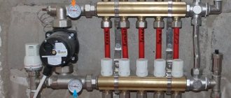
This should be done not through the heating boiler, but directly through the drain and fill taps. They are located on the rear plug of the distribution manifold.
Mistake #4 - if you pump water through the boiler, there is a risk of failure of the circulation pump.
In this case, be sure to shut off the ball valves with the supply from the boiler.
Next, using a special key, close all circuits except one. This is where you will begin filling the system with water.
Also close all valves on the rotameters, except one.
Now you can connect the water hose to the drain valve on the supply comb.
A hose for draining water is connected to the return comb. After which you can slowly let the water in.
Lower the drain hose from the return comb into the sewer or simply into a bucket and wait until all the air has drained.
As soon as one water flows, the valve of this circuit can be closed and proceed to the next one. The whole procedure is repeated again.
After filling all the circuits, you can begin supplying water to the distribution system through the heating unit or the boiler itself.
Only after this do you open the ball valves on the manifold and finally release the remaining air through the air vents.
Before pouring the screed, the underfloor heating pipelines themselves should be checked for leaks.
Tests are carried out in cold water. In this case, the test pressure must exceed the working pressure by 1.5 times.
As a rule, hydraulic tests take place within 3 hours. During the first hour, every 10 minutes the decreasing pressure is adjusted to the required level.
And over the next 2 hours, a control measurement is taken.
The pressure in a working and serviceable system should not drop from the original by more than 2 bar.
Mistake #5 - trust only pressure readings, without visually and physically (by hand) checking the joints.
You definitely need to make sure that not only the tubes are tight, but also all joints and connections. The fact is that a slight undermining is not determined by a drop in pressure.
As a result, satisfied with all the readings, you will finally fill the screed and install the entire system. And after a while, these wet places will show themselves in all their glory.
As an exception, if your site has a negative temperature, pneumatic tests with compressed air or inert gas are allowed for floor-mounted systems.
The tightness of each connection is checked with a foaming compound.
Hydraulic tests are usually documented in a protocol.
Using Formulas to Calculate Diameter
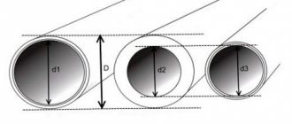
You can find out the diameter of the pipes for arranging a water heated floor by applying the formula that experts once compiled:
D=18x(p/LxG2)x 0.19, where:
- D – internal diameter of the pipeline;
- p – pressure of the pumping equipment used for the heating system; this parameter can be found out from the documentation attached to the circulation device;
- L – designed length of the heating circuit. Do not forget that the maximum length of the underfloor heating pipe is limited;
- G is the volume of water required to ensure circulation of the heating system; the value of this value can also be taken from the technical documentation;
- 18 and 0.19 are constant parameters that were obtained as a result of compiling this formula.
Characteristics of pipes for water heated floors
The construction of a water heated floor is a complex and time-consuming process, especially when using a concrete screed and the need to reinforce the structure. Therefore, great demands are placed on the pipes that are planned to be laid in the “pie”.
Important! The use of standard PVC water pipes is prohibited.
Since they cannot withstand high loads that are formed due to high temperatures and pressure created in the pipeline.
The main requirement for a pipeline in a warm water floor, both in a private house and in an apartment, is durability and tightness. It is necessary that during a sharp temperature change the system does not depressurize.
After all, if there is a screed, it is difficult to find and eliminate the defect. In addition, it must withstand the effects of aggressive chemical compounds found in the coolant and mechanical loads. The elasticity of the contour is of no small importance - it should bend easily.
We should not forget about the level of thermal conductivity when choosing a coil for water-type underfloor heating; the higher this coefficient, the more efficiently the device works. And also, regarding the degree of expansion when heated, up to 0.25 mm/mK is considered acceptable.
Pipes are produced in coils with a certain footage. When purchasing, remember that the loops must be solid, without joints.
For your information! The pipeline for heated water floors must be marked to permit their use in heated floors.
Pipeline length calculation
Before choosing a pipe for a warm water floor, you need to decide on its diameter, which depends on the area of the heated room, or more precisely, on the length of the coil that needs to be laid to ensure a normal degree of heating.
When calculating the length of the pipeline, use graph paper and proceed as follows:
- Determined with the pipe layout. They can be laid in a spiral, in the shape of a “snail” or “snake”, and in different variations. The installation technology largely depends on the presence of window and door openings in the room - they are areas that require additional heating.
- The selected layout of the heating circuit is transferred to paper, taking into account the scale and installation step, having previously reduced the area of the room into areas where large furniture is located.
- Perform calculation. When making final calculations, you should take into account the distance between the room and the heating equipment.
You can also determine the length of the tube for a warm water floor using formulas, but using graph paper is a simpler option.
A specific example of calculating a heating branch
Let's assume that you need to determine the parameters of the thermal circuit for a house with an area of 60 square meters.
For the calculation you will need the following data and characteristics:
- room dimensions: height – 2.7 m, length and width – 10 and 6 m, respectively;
- the house has 5 metal-plastic windows of 2 sq. m;
- external walls - aerated concrete, thickness - 50 cm, Kt = 0.20 W/mK;
- additional wall insulation – polystyrene foam 5 cm, Kt=0.041 W/mK;
- ceiling material – reinforced concrete slab, thickness – 20 cm, Kt=1.69 W/mK;
- attic insulation – 5 cm thick polystyrene foam boards;
- dimensions of the entrance door - 0.9 * 2.05 m, thermal insulation - polyurethane foam, layer - 10 cm, Kt = 0.035 W/mK.
Next, let's look at a step-by-step example of performing the calculation.
Step 1 - calculation of heat loss through structural elements
Thermal resistance of wall materials:
- aerated concrete: R1=0.5/0.20=2.5 sq.m*K/W;
- expanded polystyrene: R2=0.05/0.041=1.22 sq.m*K/W.
The thermal resistance of the wall as a whole is: 2.5 + 1.22 = 3.57 sq. m*K/W. We take the average temperature in the house to be +23 °C, the minimum temperature outside is 25 °C with a minus sign. The difference in indicators is 48 °C.
Calculation of the total wall area: S1=2.7*10*2+2.7*6*2=86.4 sq. m. From the obtained indicator it is necessary to subtract the size of the windows and doors: S2 = 86.4-10-1.85 = 74.55 sq. m. m.
Substituting the obtained indicators into the formula, we obtain wall heat loss: Qc=74.55/3.57*48=1002 W
By analogy, heat costs through windows, doors and ceilings are calculated. To assess energy losses through the attic, the thermal conductivity of the flooring material and insulation is taken into account
The final thermal resistance of the ceiling is: 0.2/1.69+0.05/0.041=0.118+1.22=1.338 sq. m*K/W. Heat loss will be: Qp=60/1.338*48=2152 W.
To calculate heat leakage through windows, it is necessary to determine the weighted average value of the thermal resistance of the materials: double-glazed window - 0.5 and profile - 0.56 sq. m*K/W respectively.
Ro=0.56*0.1+0.5*0.9=0.56 sq.m*K/W. Here 0.1 and 0.9 are the proportion of each material in the window structure.
Window heat loss: Qо=10/0.56*48=857 W.
Taking into account the thermal insulation of the door, its thermal resistance will be: Rd=0.1/0.035=2.86 sq. m*K/W. Qd=(0.9*2.05)/2.86*48=31 W.
The total heat loss through the enclosing elements is: 1002+2152+857+31=4042 W. The result must be increased by 10%: 4042*1.1=4446 W.
Step 2 - heat for heating + general heat loss
First, let's calculate the heat consumption for heating the incoming air. Room volume: 2.7*10*6=162 cubic meters. m. Accordingly, ventilation heat loss will be: (162*1/3600)*1005*1.19*48=2583 W.
According to these room parameters, the total heat costs will be: Q=4446+2583=7029 W.
Step 3 - required power of the thermal circuit
We calculate the optimal circuit power required to compensate for heat loss: N=1.2*7029=8435 W.
Next: q=N/S=8435/60=141 W/sq.m.
Based on the required performance of the heating system and the active area of the room, it is possible to determine the heat flux density per 1 sq. m
Step 4 - determining the laying pitch and contour length
The resulting value is compared with the dependence graph. If the coolant temperature in the system is 40 °C, then a circuit with the following parameters is suitable: pitch – 100 mm, diameter – 20 mm.
If water heated to 50 °C circulates in the main, then the interval between branches can be increased to 15 cm and a pipe with a cross-section of 16 mm can be used.
We calculate the length of the contour: L=60/0.15*1.1=440 m.
Separately, it is necessary to take into account the distance from the collectors to the heating system.
As can be seen from the calculations, to install a water floor you will have to make at least four heating loops. We looked at how to properly lay and secure pipes, as well as other installation secrets here.
