To control the operation of the heating system (primarily the boiler itself), automation is required. It ensures safety, maintaining the desired temperature, turning off the burner, adjusting the flame, protection against overheating, and saving fuel.
Automation for gas heating boilers can be either volatile or non-volatile.
Modern boilers are usually already equipped with all the necessary appliances. Automation of old-style gas heating boilers can be purchased separately in the form of a ready-made multiblock, which includes a gas valve, thermostat, pressure and draft sensors, and an actuator relay.
On old boilers, automation must also be installed in accordance with safety standards.
Features and principle of operation of gas boiler automation
Stable operation of a gas boiler depends on many factors: stable pressure, timely supply and shutdown of gas, ignition and control of the presence of flame. The principle of operation of automation is to ensure control over all these parameters and is necessary for the stable operation of household gas boilers.
The first regulators had a simple design and ensured that gas did not leak due to flame extinction. In some boiler models, there was no igniter; the main burner was manually ignited at minimum power. The gas supply was adjusted in three modes.
Modern automation for gas heating boilers has improved functionality and ensures complete operational safety.
The automation has a design and operating principle that allows for interchangeability. In most cases, you can replace the mechanical regulator in the boiler with an electronic one.
Mechanical and electronic automation
There are two main types of automation that regulate the operation of the boiler. Based on their design, it is customary to distinguish between mechanical and electronic regulators.
Each type of controller has its own characteristics, which affect the principle of their operation:
- Mechanical automation of household gas boilers - the operating principle is based on the use of the electrical potential of a thermocouple. The device consists of two metal rods, made of metals of different densities, soldered together in several places. When heated, a low-potential voltage arises, acting on the mechanical gas supply valve and holding it in the open position. When cooling, electricity stops being generated and a reverse process occurs, leading to the closing of the gas valve. The design also uses a thermostat installed in the water heating circuit. Inside the device there is a metal rod (Invar). Under the influence of temperature, the inner strip of metal lengthens or shortens, opening or closing the valve that regulates the gas supply to the burner.
Electronic automation has a complex design. In addition to the main tasks, turning off the gas burner and adjusting the heating intensity of the coolant, it ensures safe operation and other functions. Modern fifth-generation boilers are equipped with built-in weather-dependent automation or a separate programmer that can automatically control operation during the week. The control is carried out by a microprocessor. The operating principle is based on the use of an electromagnetic valve and is volatile, therefore, in the event of power surges or lack of electricity, the operation of gas equipment becomes impossible.
For a gas boiler, it is better to choose electronic type automation. To prevent shutdowns during voltage surges and power outages, install an uninterruptible power supply and a stabilizer.
Volatile and non-volatile automation
The operating principle of non-volatile automation is significantly different from volatile devices. The main differences are as follows:
- Non-volatile mechanical automation - works using physical laws for regulation. The gas supply is opened by a thermocouple, which produces low-potential electricity equal to 40-60 mW when heated. The voltage holds the gas valve rod in the open position. The heating intensity is adjusted through thermal expansion of the internal rod located in the cavity of the temperature sensor.
Volatile electronic automation - in this case, the work is controlled by a microprocessor chip. The boiler design and water circuit are equipped with sensors that read information about operating parameters: gas pressure, coolant temperature, air flow intensity and draft characteristics. After processing the information received, the microprocessor chip gives signals to operate gas valves, fans and other shut-off and control valves .
The only drawback of the electronic controller is the dependence of the automation on energy consumption. The microprocessor automatically adapts to actual operating conditions, selects the optimal heating mode and ensures safety.
Electronic automation connected to room thermostats saves up to 30% gas compared to boilers operating with mechanical control units.
Automation APOK-1 with gas burner device
Ministry of Housing and Communal Services of the Ukrainian SSR Republican Industrial Association "UkrkommunmaSh" Kiev Production Association "Kievkommuntekhnika"
Passport
Installation, adjustment, preventive maintenance and repair of the APOC-1 automation with a gas burner device (hereinafter referred to as the ALOC-1 automation) is permitted only to specialized gas industry enterprises.
PURPOSE OF THE PRODUCT
Automation APOK-1 is designed for automatic protection and regulation of thermal processes of heating water boilers with a power of up to 29 kW in accordance with GOST 20548-81 and GOST 22451-77, operating on low-pressure natural gas.
Automation APOC-1 is produced in the following standard sizes indicated in Table 1.
TECHNICAL SPECIFICATIONS
CONTENTS OF DELIVERY
PREPARING THE PRODUCT FOR OPERATION
1. Ventilate the room in which the heating boiler is installed for 10-15 minutes. Check the operation of the supply and exhaust ventilation by placing a strip of paper near the air ducts.
2. Check whether the gas valves on the downstream side of the boiler and valve 2 (see figure) after the shut-off valve in front of the burner are closed.
3. Check the presence of draft by placing a strip of paper near the ignition hole.
4. Ventilate the firebox and boiler flue for 10 minutes by opening the secondary air damper 6 located on the front sheet under the burner and the igniter window 5. After ventilation, close the secondary air damper.
5. If the boiler was stopped after normal operation, the position of the water temperature regulator indicator 4 should not be changed before lighting.
6. The boiler and heating system are prepared for start-up in accordance with the instructions for the heating boiler.
OPERATING PROCEDURE
a) open the gas valve on the descent to the boiler;
b) open the igniter window 5 and bring in a burning paper bundle;
c) press plate 7 of shut-off valve I;
d) wait until the gas on the igniter ignites and remove the paper bundle;
e) check whether the flame is well washed around the end of the bimetallic plate and close the ignition hole with a damper;
f) keep the shut-off valve plate 7 pressed for 1 minute, then release;
g/ smoothly turn the tap handle with the safety lever 3 installed on it, after the shut-off valve, while the gas should pass to the burner;
h) if the igniter circuit does not warm up the end of the bimetallic plates well or the gas along the entire igniter treadmill ignites, stop ignition and release
plate 7. Repeat ignition, proceeding strictly in the previously specified sequence.
2. Stop the boiler.
a) close the tap on the descent to the boiler;
b) close valve 2 after the shut-off valve;
c) when stopping the boiler for a short time, it is recommended to turn off only the burner by turning the handle of tap 2, while only the igniter lights up, which facilitates further ignition;
d) if the main parameters deviate beyond the established limits, the gas to the burner and igniter is automatically cut off. In this case, you must immediately close the gas taps in the order specified in points “a” and “b”;
To identify and eliminate automation malfunctions or other problems, it is necessary to call a fitter at a specialized gas industry enterprise.
MAINTENANCE
1. The temperature that the water temperature regulator 4 must maintain is set by turning the pointer to the required position. To increase the temperature maintained by the regulator, turn the pointer towards the “hot” side, and to lower it - towards the “cold” side. A thermometer must be installed on the boiler outlet manifold, which is used to control and set the temperature of the heated water entering the heating system.
2. It is prohibited to regulate the gas flow to the burner using taps located in front of the shut-off valve, including the tap on the lower side to the boiler.
3. The regulation principle carried out by the APOK-1 automation ensures a stable air temperature in the room with small external changes in meteorological conditions without outside intervention. If there are significant changes in the heat loss of the building, it is necessary to call a specialized gas service technician to re-adjust the automation.
4. Automation should be protected from mechanical damage; no objects should be placed on the automation devices.
5. It is necessary to periodically clean the igniter and burner treadmill holes to prevent clogging or carbonization of these holes.
SAFETY
1. If the smell of gas is detected, it is prohibited to start ignition.
2. While observing the combustion, do not put your face close to the ignition hole.
3. Operating a boiler with a faulty automatic safety unit is not allowed.
CERTIFICATE OF ACCEPTANCE
The APOC-1 automation system was manufactured in accordance with TU 204 of the Ukrainian SSR 124-82, tested, accepted by the quality control department and declared fit for use.
QC release date
TRANSPORTATION AND STORAGE
APOK-1 automation is transported to the customer by any type of transport.
The placement of APOC-1 automation assembly units and their fastening during transportation should ensure their safety.
APOK-1 automation systems should be stored at temperatures from +5 °C to +35 °C and relative air humidity in the range of 60-80%.
After transportation in packaging at sub-zero temperatures, the APOK-1 automation must be kept at storage temperature for 24 hours before installation on the boiler.
WARRANTY
The manufacturer guarantees compliance of the APOK-1 automation with the requirements of the technical specifications TU 204 of the Ukrainian SSR 128-82, subject to the conditions of operation, storage, transportation and installation.
The warranty period is 12 months from the date of sale through a retail network, and when supplied for off-market consumption - from the date of receipt by the consumer.
The warranty period for the operation of the APOK-1 automation system, which has been duly assigned the State Quality Mark, is 18 months from the date of sale through a retail distribution network, and for supplies for off-market consumption - from the date of receipt by the consumer.
If factory defects in the automation are detected during the warranty period, the owner should call a representative of a specialized gas enterprise to draw up a report indicating the malfunction and send: the faulty unit, report and passport to the manufacturer at the address: 252116, Kiev-116, st. .Sholudenko, 30 KPO "Kievkommuntekhnika".
Operating principle and types of volatile systems
How does a gas boiler automation work? Volatile systems require electricity and are complex electronic devices that independently regulate fuel supply and flame power, which means they help save money on home heating.
Room thermostat
The thermostat is located in the room where the temperature needs to be controlled. Sensors make measurements.
If the temperature drops below the set value, the thermostat sends a signal to the boiler and it automatically starts working.
When t reaches values that are comfortable for residents, the valve closes and the boiler stops working.
Connects to the boiler with a cable.
Daily programmer
The device performs the same role as a thermostat, but with the ability to set a program for 24 hours. Programs the temperature for heating and hot water supply by time. A day later the cycle repeats.
It is connected to the boiler by cable and via radio.
Weekly programmer
It has greater capabilities for programming the climate in the house. There are ready-made modes and customizable ones. Range of action – from 30 m and more. The data is displayed on a backlit display. Devices can be selected according to color for a specific interior.
Weekly programmer Auraton 2025
Modern devices not only regulate the temperature, but also carry out self-diagnosis of the equipment, control the operation of the pump and protect the boiler from freezing.
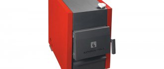
Gas equipment for KChM 630 EUROSIT
In distant post-Soviet times, when natural gas for the population cost nothing, solid fuel boilers began to be produced with gas fittings of the APOK-1 type, which replaced solid fuel in the form of coal and wood. The gas supplied to the KChM had a complex and cumbersome device with burners that consumed gas within large limits. Nowadays, they have begun to produce more modern and economical gas boilers that consume less gas, but not all owners of private houses can afford them. Of course, old KChM boilers are not so aesthetically pleasing and modern, but if they are modernized, they can serve as heating devices for many years.
Automation units for gas boilers ZhMZ
The boiler automation unit is one of the most important components included in the design of AOGV/AKGV gas boilers.
The main purpose of the automation unit is to pass gas through itself, distribute it to a constantly working pilot burner through an igniter to maintain a constantly burning torch, and to the main burner at a certain frequency.
Also, the main purpose of the automation unit is a shutdown function to block the gas supply when the protection systems are triggered and when the burner is blown out.
Initially, the automation unit consisted of a cast housing and a magnetic box. Subsequently, the automation unit was structurally improved, became collapsible, and now consists of two main components: a magnetic valve and a thermostat unit. This design allows for partial replacement of a faulty unit without completely replacing the entire unit. Such automation units are used on modern AOGV/AKGV boilers of the “Economy” series with a power of 17.4 kW, 23.2 kW and 29 kW. On boilers with a power of 11.6 kW, the automation unit was not structurally changed.
In our online store you can buy an automation unit for ZhMZ boilers at the manufacturer’s price list!
We sell automation units for any models of AOGV boilers from the Zhukovsky Machine-Building Plant at the most affordable prices, since we are its official dealers.
Flame sensor - draft sensor - bimital plate APOC-1
APOC-1 Mechanical thrust-flame sensor. (bimital plate)
-
- Remove this product from my favorites list
- Add product to Favorites
- Seal
- More details
- Reviews
Flame sensor - draft sensor - bimital plate APOC-1
For safe and automatic operation of the gas heating boiler, a protection and automation system is provided. It is responsible for maintaining the specified temperature conditions, as well as for the safe operation of the unit. One of the main elements of unit protection is the gas boiler draft sensor.
1 Purpose of the draft sensor
2 Design and principle of operation of the draft sensor
3 Reasons why the traction sensor is triggered
4 Popular models of draft sensors for gas boilers
Purpose of a draft sensor A draft sensor or thermostat is a device for determining the intensity of draft in the chimney of a gas boiler. Its main function is to provide a timely signal about an unacceptable amount of draft in the boiler.
A malfunction of the traction sensor can result in an emergency. After all, sufficient draft is necessary not only for drawing out smoke, but also for efficient combustion of gas. If there is no draft, then the combustion will be unstable, and this can affect the integrity of the entire unit. Poor draft can cause a gas boiler to go out.
Design and operating principle of a draft sensor There are 2 types of gas boilers: with natural and forced draft. The traction sensors in them are also different. Boilers with natural draft use an open combustion chamber, and draft is created by selecting the correct dimensions of the chimney (height and cross-section). Such units use a traction sensor based on a bimetallic element. This is a plate of certain dimensions with a contact attached to it. It is installed in the gas path of the unit and reacts to temperature changes. If the draft in the boiler is good, the temperature will be low. As the thrust intensity drops, the temperature will begin to rise and cause the metal of the plate to expand. Its material is selected in such a way that when a critical temperature is reached, the contact is disconnected and the gas valve closes. After the temperature drops, the valve closes again. The critical temperature is set by the gas boiler manufacturer and can be located in the range of 75-950C.
On a note. “Backdraft” - this phenomenon occurs in the absence of vacuum in the combustion chamber. It can only be observed in boilers with natural draft and an open combustion chamber. During normal operation of the boiler, air is constantly sucked into the combustion chamber, and if the draft disappears, the smoke will flow in the opposite direction, not from the room, but into it. This is “reverse thrust”.
Boilers with forced draft have a closed combustion chamber, and the draft is created by the operation of a fan. Therefore, in such boilers a draft sensor in the form of a pneumatic relay is used. It provides control over the operation of the fan and the intensity of removal of combustion products. The sensor is a membrane that bends under the influence of the flue gas flow created by the smoke exhauster. If the flow weakens, then the membrane voltage drops, at a certain moment the contacts open and the gas valve closes.
Reasons for the draft sensor to be triggered Various factors can cause the draft sensor to trigger: Clogging of the chimney. Incorrect installation of the chimney for a gas boiler, or an error in calculating its dimensions. The gas boiler was installed incorrectly. Fan stop (in forced draft boilers).
Attention! If the traction sensor triggered, then there were good reasons for this; you should look into them carefully. But it is strictly forbidden to forcibly close the contacts of the draft sensor to resume boiler operation. It is also not permissible to operate the boiler without a working draft sensor.
A temperature sensor for boilers with natural draft and a pneumatic sensor for boilers with forced draft are reliable elements of protection for gas heating boilers. For additional protection, you can install an external air gas analyzer to detect gas contamination. This will ensure complete control of the boiler operation, even if one of the sensors malfunctions.
Automation for pump
Regulates the operation of the system, controlling many functions, such as, for example, pressure, water distribution.
For normal operation, the following components are required: a manifold that provides water supply, a relay that controls the pump, a pressure gauge that measures pressure, a dry-running sensor that prevents the device from overheating if the water runs out.
All automation responsible for the pump is divided into several models, based on the time of creation:
First generation automation;
The first simplest water supply design. Used to solve simple problems when it is necessary to provide a room with a source of water. It consists of three components: a dry running sensor, a hydraulic accumulator that performs the task of accumulating water and contains a membrane, and a relay that controls water pressure. It usually does not cause any difficulties during installation, since the system completely eliminates complex electrical circuits. The mechanism is also extremely easy: the order is cyclical—when the water is completely filled, the pump turns off, then the cycle repeats.
Third generation automation
It is a more worthy version of its predecessors, and costs more accordingly. The unit stands out for its greatest reliability, efficiency, improved safety program, and most importantly, maximum accuracy of the device.
To maintain the device in automatic mode, a relay is installed. The mechanism is simple: when the water pressure decreases, the relay starts the system, and similarly, when the pressure increases, it stops.
Thermostat to turn the pump on or off
The most common type of automation for a pump in home heating. Mechanism: first, information is collected from the sensor, then the indicators are compared, the operation of the pump depends on this. For example, if the owner sets the mode to +60 and the hysteresis to +5, then the water must be +65 for the system to start, and for it to stop, the temperature must be +55.
Single-circuit or double-circuit?
The design of heating units depends on the number of circuits - liquid supply and discharge lines - in its composition. Single-circuit ones have a low cost. When installed, fuel costs will be low. Therefore, they are considered less expensive. These devices are only suitable for heating small rooms. If hot water is required for household purposes, a boiler is installed.
The double-circuit heats the room and supplies hot water. But simultaneous operation of both systems is impossible. For example, when a hot water tap is turned on, the heating system turns off. If a small volume of liquid is required at a time, a double-circuit flow-type boiler is well suited. If you need a large amount of hot liquid, you need to choose models with a boiler.
Gas unit operation diagram
How does a gas heating boiler work? Central systems use natural gas as a source of energy and heat. There are two combustion options: methane and a mixture of propane and butane. It is worth examining the main aspects of the operation of heating equipment.
Operating principle of the boiler
The operating principle of all gas heating boilers can be described as follows:
- In equipment connected to the gas supply system, the ignition system is activated.
- A spark from electricity ignites the burner.
- The igniter ignites the main burner, which can have different designs.
- The fire heats the water jacket and coolant. As a result, the heat exchanger heats the water to a certain value specified by the user. After which the burner turns off.
- If the temperature drops, the sensors send a signal to the automation, which resumes operation of the system until it reheats.
Single-circuit boiler
Gas boiler design
Models from different manufacturers may differ slightly in design and arrangement of components, but they have several common parts:
- Valve for supplying or shutting off fuel.
- Burner.
- Electrical block.
- Fire sensor.
- Gas combustion chamber.
- Fan.
- Heat exchanger.
- Set of sensors.
- Expansion tank.
- Water filter.
- Set of valves.
- Bypass.
- DHW filter.
It is worth considering the operation of the main components separately in order to understand the operation of the boiler as a whole.
Gas burner and smoke removal system
The burner is the main module that provides heating of the coolant. In most modern devices, it can regulate the volume of gas supplied. The adjustment occurs under the influence of a thermostat, which gives a signal when the temperature is too hot or the temperature drops.
Gas is supplied through a valve. It is regulated by an electric power unit, which is controlled by the automation system in the boiler. This allows you to control most of the DHW operation processes.
Heat exchangers
There are two types of heat exchangers in the system: primary and secondary. The first is located above the burner and includes several copper pipes through which the coolant circulates. The secondary one is needed to heat water from hot water supply. It looks like a set of lamellas, in the spaces between which liquid circulates from the primary and secondary heat exchanger.
Double-circuit boiler
DHW system
This system is the main difference between double-circuit elements. It is through this that you can quickly gain access to hot water. It is provided by a secondary heat exchanger, several valves and sensors that control the operation of the device. The main sensor is the flow sensor.
The liquid begins to heat up in the main heat exchanger. Afterwards, it moves inside the housing with the help of a pump, passing through a secondary system of lamellas, in which it is additionally heated.
Bypass
This bypass pipe connects the forward and return pipes. Additionally, a valve is attached to it, which opens if necessary, and part of the water begins to move into the return pipeline.
Expansion tank
This part of the system is required to stabilize pressure during heating. Due to increased pressure, water expands, which can damage equipment. The tank consists of 3 components:
- container for water;
- membranes;
- space for gas.
Due to the bends of the membrane, it balances the pressure in the system.
Control board and sensors
The control unit is a mandatory module required for the operation of the boiler. It is through this module that you can set the required operating mode and regulate the operation of the elements.
Diaphragm tank
Varieties
All equipment of an automatic gas water heater that controls the heating system modes can generally be divided into two main components. Moreover, the first group includes safety devices that are capable of maintaining the operation of the AGV in a given temperature range and ensuring the reliability of the system.
The second group includes automatic safety devices designed to ensure the most comfortable operation of the units. For example, a built-in electric ignition or an electronic thermometer is used for this purpose.
The mandatory list of safety automation systems used for gas boilers includes a regulated group of elements.
- A unit that controls the pilot flame. It should include automatic elements for gas units that have the ability to independently stop the gas supply.
- A unit that controls heating parameters of the coolant, capable of stopping heating when the maximum permissible level is reached.
- A module that controls draft, capable of interrupting the gas supply to the operating burner in the event of violations of the exhaust outlet.
- A safety valve that allows the release of excess pressure in the coolant.
If all the specified elements are present that ensure adjustment of the equipment of the existing gas boiler, the existing heating system is recognized as suitable for safe use and is allowed to operate. An entry about this is made in the automatic safety log of the water heating boiler.
Portal about construction
Statistical studies show that at least 50% of heating equipment runs on natural gas.
This popularity is due to objective reasons - convenience and ease of use and the relatively low cost of the energy carrier (natural gas).
Talking about an automatic gas boiler in this article, we will immediately make a reservation that any modern gas boiler is automatic, that is, it does not require daily cleaning and loading of fuel like boilers running on solid fuel or periodic refueling like boilers running on liquid fuel.
The difference is that “simple” boilers are equipped with a standard set of automation and protection, while “complex” boilers are equipped with additional options that improve their maintenance and configuration.
Commissioning of a wall-mounted boiler
For installation and initial start-up of a wall-mounted gas boiler, it is better to contact the organization of the specifics in question. The presence of all approvals and appropriate qualifications for the installation of water heating equipment on the part of the service center will allow you to purchase a warranty, as well as extend it with proper operation in subsequent years. All this must be accompanied by documentation in the form of an act or card with a stamp and signature.
In addition to the provided warranty, when contacting specialists, another advantage is the safe installation and adjustment for economical operation of the gas boiler. Safety means the absence of gas leakage and the risk of unwanted ignition.
Installation features
According to SNiP requirements, the heating boiler must be connected to the gas main using a copper pipe or a stainless steel bellows hose. The presence of a gas shut-off valve is mandatory. It is also possible to use various types of adapters and fittings for connection. We must not forget about the presence of gaskets and sealing materials at the joints.
Gas boilers can only be mounted on fireproof walls at a distance of at least 2 centimeters. Otherwise, a fireproof material (plaster, metal or ceramics) must be placed between the boiler and the wall. The distance to the wall should be more than 3 centimeters, and the sheet area should exceed the dimensions of the heating installation in width and height.
Another important condition for placing a gas boiler is the presence of a hood and a window with elements of free air access. After installing the heating boiler, it is necessary to check for gas leaks using an electronic device or a soap solution.
Commissioning
The sequence of actions when starting a wall-mounted gas boiler may differ slightly and be as follows:
Working with AOGV
It begins when the gas supply is blocked - the corresponding valve closes. And this is a general principle for similar work with any boilers and columns.
How to clean the burner of an AOGV gas boiler? After shutting off the gas, this element is removed from its position. The burner has a nozzle
It is carefully unscrewed and carefully cleaned with a brush. The burner itself is cleaned by blowing using a special pump. Then the nozzle and burner are returned to their place
Then the nozzle and burner are returned to their place.
These are general criteria. And the details are presented on the next two models.
First. AOGV 11.6-3. This is a reliable and practical device.
But after a certain period of operation, it is thoroughly cleaned. The process goes like this:
The burner block is removed
To do this, the pan of the apparatus is rotated, and three tubes are disconnected from the automation unit: contact, gas and thermocouples
Carefully unscrew the nuts located on the fittings of the automation mechanism. The paronite gasket on the main gas pipe is removed and its conditions are studied
If it is damaged, it needs to be replaced. The marked pallet is taken out through the groove, which is as close as possible to the tubes
The casing is also pulled out along with it. When fixing the lower part of the tray, point it towards you and remove the remaining holders (two pieces) from the engagement. This entire assembly falls to the floor. The main burner is examined and cleaned. The igniter nozzle is inspected. The wick and thermocouple are unscrewed. The box-shaped casing is separated from the pilot burner. This clears the way to the nozzle. If it is brass and there is plaque on it, it can be removed with fine-grained sandpaper. Cleaning the nozzle. To do this, thin copper wire and a blowing method under high pressure are used. The second action is carried out by a special pump from the side where the tube is connected to the tee
The same sandpaper is used to very carefully clean the bend of the thermocouple tube.
After this work, all the parts are assembled using the reverse algorithm. Smoothly, avoiding distortions, lift the entire block. The burner should be inside the housing, and the igniter and thermocouple should not touch the casing flange.
From the side of the tubes, the entire assembly should be tilted towards itself with a slight downward slope. The opposite side of the tray should rise.
Then feed it forward and simultaneously put on a pair of distant holds. They should be on the casing flange. The nearest hook goes to a cut groove. After it enters there, the entire pallet rotates in the opposite direction to the clockwise direction. The gas pipe should be positioned only under its branch pipe of the automation unit.
Next, it is tested how correctly the gaskets fit, and all the tubes are returned to their places. The wrench tightens the nuts on two tubes: the igniter and the gas tube.
Before reassembling the thermocouple tube, its contact areas are carefully but carefully cleaned. The nut here is tightened with your fingers.
The final stage is to check the tightness of all connections for potential leaks. If they are absent, the boiler turns on. If available, these places are covered with sealant, the nuts are tightened.
The second model is AOGV-23.2-1 Zhukovsky.
It works like this:
- The nut is unscrewed so that the gas pipe passes through.
- The angle, igniter and thermocouple are unscrewed.
- All burners in the set stretch outward and extend to the side towards the user. If there are difficulties with their movement, loosen and unscrew the studs with pliers. Clean all jets and other components.
- Disassembly of burners. To do this, unscrew 4 pins on both sides.
- The plates with slots are removed from the top of the burners, then the springs. All parts are thoroughly cleaned.
- Reassemble all elements in reverse order.
After reassembly, a leak test is carried out to examine how tightly the burners adhere to the body.
What automatic settings are there?
Currently, the market offers consumers a wide selection of control devices. Therefore, you need to know what automation systems for home heating systems generally exist, and what to give preference to.
Room thermostat
According to installation criteria, there are:
- Wired thermostats. The advantage of this type is the ability to supply power up to approximately 50 meters via wires.
- Wireless thermostats. The advantage is that it is not necessary to create holes for the wires. However, they have a significant drawback - reinforced concrete walls reduce the signal power.
According to functionality they are distinguished:
- Simple thermostats. They retain the desired level of warmth.
- Programmable thermostats. Such devices are capable of setting a certain number of degrees for a whole week in advance (the period depends on the model) with maximum accuracy down to seconds. The advantages also include cost savings due to weekly programming.
Thermostats are also distinguished:
- Electronic thermostats. The kit contains three components: temperature sensor, signal transmitter, relay. The main advantage of the device is the maximum accuracy of the equipment. Don't forget ease of use.
- Mechanical thermostats. The basis of the devices is the ability to change properties under the influence of temperature levels. Due to temperature changes in the gas membrane, a circuit is closed or opened, causing certain mechanisms to work.
- Electromechanical thermostats. The mechanism of the device is much simpler than an electronic one. The main element is the relay. The node looks like a tube, which is filled with a special substance that reacts to temperature. If the boiler heats up, the substance expands; similarly, when the boiler cools, the substance contracts. And the drive, dependent on the substance, regulates the temperature thanks to an electrical circuit.
Connection can be made to:
- Kotlu;
- To the pump;
- Servo drive;
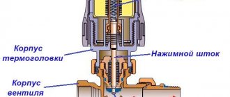
Thermal head
This is a thermostatic element that, under the influence of the external environment, slightly opens or closes the radiator. An inexpensive type of automation for heating a home. A significant advantage is that the thermal head is very convenient for local heating, and there are also significant cost savings. Of the minuses: firstly, the adjustment occurs according to standards consisting of abstract numbers, not degrees. Secondly, the sensor measures the degree of heat around the installation, but not the room, which reduces the accuracy of the device.
Weather-compensated automation
The design of weather-dependent automation for heating a house is simple: as the weather outside decreases, the temperature of the coolant increases. However, a weather-dependent installation has a very significant drawback - the system sometimes does not have time to adapt to the temperature, and, therefore, the effect is delayed. The especially mentioned disadvantage manifests itself if an addition is connected - heated floors. The disadvantages include the fact that the devices do not operate entirely correctly, approximately, so the change is noticeable only during seasonal climate changes. It is worth noting that the prices for the unit are relatively high. But the units will be very convenient in production, large-scale houses (over 500 square meters).
Functions and principle of operation of security automation
In accordance with regulatory documents, automation equipment for boiler installations must stop their operation by cutting off the fuel supply in the following situations:
- the draft in the chimney is insufficient and there is a danger of burning;
- the gas pressure in the supply pipeline is too low or, conversely, too high;
- The flame on the igniter went out.
The listed situations can lead to the main burner going out and the room becoming gassed, which is unacceptable. For this reason, safety automatics for gas boilers must be installed on all old-style boilers where it was not provided by the manufacturer. Although it is often cheaper to replace a heater than to purchase and install automation on an old one. In addition to preventing gas contamination of the room or fumes, its functions also include maintaining the temperature of the coolant at a certain level specified by the user.
To understand how the automation of a gas boiler works, let’s briefly analyze its structure. It should be noted that both foreign and Russian manufacturers use the same operating principle in their products, although the design of the devices may differ significantly. Automatic gas valves from Italian manufacturers are traditionally considered the simplest and most reliable, which is why they are most common.
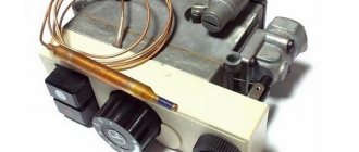
A prominent representative of such gas appliances is the Italian automatic SIT, or rather, its most popular modification 630 EUROSIT, whose device is shown below.
Automation device SIT
All structural elements are placed in one housing, to which gas pipelines are connected. In addition, a capillary tube from draft and temperature sensors (thermocouples), a gas supply line for the igniter and a cable from the piezoelectric element are connected to the device. Inside there is a shut-off solenoid valve, whose normal state is “closed,” as well as a gas pressure regulator and a spring valve.
Any automatic gas boiler equipped with a combined gas valve EUROSIT or another is started manually. Initially, the fuel path is blocked by an electromagnetic valve, which opens by pressing the adjusting washer, after which the fuel fills the chambers of the device and goes through a small gas pipeline to the igniter. While holding the washer, press the button of the piezoelectric device and ignite the igniter, heating the temperature-sensitive element for 10-30 seconds. This, in turn, generates a voltage that keeps the solenoid valve open, after which the adjusting washer can be released.
Then everything is simple, we turn the washer to the required division and thereby open access of fuel to the burner, which is independently ignited by the igniter. Since the automation of gas boilers is designed to maintain the set temperature of the coolant, human intervention is no longer required. The principle here is this: when heated, the medium in the capillary system expands and acts on the spring valve, closing it when it reaches a high temperature. The burner goes out until the thermocouple cools down and the gas supply resumes. You can study the operation of Italian SIT automation in detail by watching the video.
By material and type of heat exchanger
Heat exchangers can be:
- cast iron;
- copper;
- aluminum-silicon;
- made of carbon or stainless steel.
The design of the heat exchanger may also vary.
The most popular are separate heat exchangers. Heating water flows separately, and water for residents’ household needs passes separately. They are a little more expensive, but more reliable.
A bithermic heat exchanger looks like a pipe within a pipe. In the inner pipe there is DHW water, which needs to be heated, and in the outer pipe the heating coolant circulates.
The third type is a heat exchanger in which a coil is built in. The container with water is heated by the coolant flowing in the coil. An indirect heating system is good for everyone, but in the summer you will either have to heat the boiler or live without hot water.
The bithermic option is not recommended for use where there is hard water. And be prepared that every time scalding water will flow out of the tap first, and only then at the temperature you need.
Setting up the boiler yourself
Correct adjustment of a gas boiler is needed for:
- saving resources;
- comfortable stay in the room;
- increasing the service life of equipment.
First of all, it is necessary to correctly determine the power of the heating equipment
It is important to take into account the features of the room: the number and area of windows, doors, the quality of insulation, the material from which the walls are made. The minimum calculation is based on heat loss per unit of time
As is known, the heating power is directly dependent on the modulation of the gas burner
If you have an electronically controlled unit, then the thermostat is activated, which is connected to the room thermometer
As you know, the heating power is directly dependent on the modulation of the gas burner. If you have an electronically controlled unit, then the thermostat is activated and connected to the room thermometer.
The adjustment is carried out automatically: the thermometer measures the temperature in the room. As soon as its indicators drop below comfortable levels, it sends a signal to start the burner or increase the flame power.
In normal mode, the thermometer monitors the temperature in only one room. But if you install valves in front of each radiator, there will be control in every room.
You can adjust the burner manually by operating the gas valve. This is true for atmospheric boilers with an open combustion chamber. For example, in the Protherm Cheetah and Protherm Bear models, the valve is controlled by an electric motor. To change the settings you need to go to the service menu. Usually this work is performed by a specialist, and the user himself acts according to the instructions.
However, it is still necessary to know how to call up the hidden menu for adjustments. Let's look at a few examples.
Before going to the menu and setting up, you need to perform the following steps:
- open the taps on the batteries;
- the room thermostat must be set to maximum values;
- in the user settings, set the maximum temperature mode, which you usually set at the lowest possible temperature outside. The burner always turns off when the readings are 5°C higher than the set values. For example, at 75°C, shutdown will occur upon reaching 80°C;
- The coolant should be cooled to 30°C.
For Protherm Gepard:
- You need to hold down the Mode key on the panel. As soon as you see zero on the display, set the value to 35 by pressing “+” and “-“.
- Next, press Mode to confirm;
when d.0 lights up on the screen, you need to enter the line number in the menu. These manipulations are also performed by pressing “+” and “-” d. (number). In order to set the maximum burner power, you need to select d.53, for the minimum - d.52.
- In order to proceed to the selection of a parameter, Mode is also used, it changes “+” and “-“.
- The installation receives automatic confirmation.
- Return to the original menu and hold Mode.
While making adjustments through the panel, monitor the change in flame and temperature intensity.
Display of the gas boiler Proterm Panther
For Proterm Panther the procedure is different:
- Hold Mode for about seven seconds.
- Next, enter code 35.
- The entry is confirmed.
- When d.00 appears on the left side of the screen, you must enter a number using two buttons.
- Then change the parameter on the right side of the screen using the 3 keys.
- After confirmation, click mode to exit the menu.
Electric and diesel heat generators
Connecting a diesel fuel boiler to the radiator system is identical to piping gas-using installations. Reason: a diesel unit operates on a similar principle - an electronically controlled burner heats the heat exchanger with a flame, maintaining the set coolant temperature.
Electric boilers, in which the water is heated by heating elements, an induction core, or through the electrolysis of salts, are also connected directly to the heating. Automation located in an electrical cabinet connected to the network according to the electrical diagram provided is responsible for maintaining temperature and safety. Other connection options are shown in a separate publication on the installation of electric heating boilers.
Wall-mounted mini-boiler rooms equipped with tubular heaters are intended only for closed heating systems. To work with gravity wiring, you will need an electrode or induction unit, which is tied according to the standard scheme:
If you look at it, there is no need for a bypass here - the boiler will not work without electricity either
Flame and draft sensors
Flame and draft sensors work on this principle. The draft sensor reacts to deteriorating smoke draft and transmits an impulse to the control system. It is located in the smoke hood. Equipped with a plate made of an alloy of two metals: iron and nickel. When draft deteriorates, flue gases accumulate and heat the plate. It becomes deformed, the contacts open, and the flow of fuel into the combustion chamber stops. When the temperature decreases, the plate returns to its normal state.
The temperature sensor works on the same principle. When the water in the boiler heats above the set temperature, the lever mechanism is activated and the temperature regulator valve closes. The gas supply stops and the burners go out.
When the water cools, the sensor bellows contracts, the lever mechanism is activated, the temperature regulator valve opens, gas begins to flow, and the burners light up.
Review of the best models and manufacturers
The most famous brand among Western manufacturers is the Italian automation company EUROSIT, which is popular throughout the post-Soviet space.
American automation manufacturers Honeywell are confidently in second place, whose equipment is distinguished by a more loyal pricing policy. At the same time, American technology is practically not inferior to Italy in the range of services provided.
Using the example of a model designated Honeywell VR 400, you can consider the list of useful functions:
- device for smooth ignition;
- modulation mode of hot water boilers;
- built-in mesh filter;
- a mode designed to keep the burners at low flame;
- inputs for installing a relay that controls minimum and intermediate pressure.
Among domestic manufacturers, the most famous is the Orion company, which also produces SABC security automation in the city of Ulyanovsk.
SABC security automation is known for its wide range of systems offered, which can have both the most necessary elements and a wider list of conveniences.
All SABC gas automatics, depending on cost, are divided into several consumer groups. When selecting equipment, be sure to clarify all questions with the seller.
Elements of safety and comfortable operation
The group of automatic devices for boilers includes many elements that can be divided into two large groups: mechanisms that ensure safe operation, and devices that facilitate comfortable operation of the boiler.
The following parts are responsible for safe operation:
- thermostat;
- draft and flame control sensors;
- safety valve.
The flame control sensor consists of a thermocouple and an electromagnetic gas valve that shuts off or turns on the gas supply.
The flame temperature regulator (thermostat) maintains the required coolant temperature and also provides protection against overheating. This module turns the boiler on or off as soon as the coolant reaches a critical point (maximum or minimum).
The draft control module stops gas supply to the burner as soon as the location of the bimetallic plate changes due to increased temperature (it bends when heated, blocking the pipe through which the fuel is supplied).
The safety valve is used to regulate, distribute and shut off the gas flow
In a heating system, a safety valve is an integral component of pipeline fittings, which is important in controlling the volume of coolant involved in the circuit. The hole in the valve through which gaseous fuel moves is called the seat
To turn off the device, you need to block it with a disk or piston
The hole in the valve through which gaseous fuel moves is called the seat. To turn off the device, you need to close it with a disk or piston.
Depending on the number of operating positions, gas valves can be one-, two- and three-stage, as well as modeling:
- Single-stage devices have only two operating positions: on/off.
- The two-stage device is equipped with one input and two outputs, and the valve opens when it is turned to an intermediate position, due to which the switching occurs more smoothly.
- A three-stage device is equipped with boilers that have two power levels.
- Modulating valves are used to smoothly change the power rating of devices.
Automation, used for convenience, includes options that are usually performed by users of heating systems. These include auto-ignition of the burner, self-diagnosis, selection of the optimal operating mode, and others.
Brief overview of products from popular manufacturers
The second place in popularity among foreign gas valves after the “Italians” is confidently occupied by American-made Honeywell automatics. The simplest budget model of a combined device works on the same principle as EUROSIT and has the same set of functions.
Under this brand, there are other types of automation on the market for gas boilers and other gas installations with advanced capabilities. For example, the Honeywell VR 400 model is equipped with two valves with a servo drive for working with electronic control units of gas boilers or remote controllers. The device has the following additional functions:
- smooth ignition system;
- modulation operating mode;
- built-in mesh filter;
- maintaining the burner mode “low flame”;
- additional outputs for connecting minimum and intermediate pressure switches.
Considering the operating conditions in the post-Soviet countries, the installation of automation on a gas boiler, which is adapted to these conditions, does not lose its relevance. Such devices are offered by many Russian manufacturers, among them Orion combined gas valves and SABC automation deserve attention. The latter is manufactured (Ulyanovsk), and the range of products for gas installations is very wide.
It includes both the simplest safety devices with a minimum set of functions, and equipment sets that include several units: control, power and gas burner. SABC brand products are well known to consumers for their affordable cost and maintainability.
Installing SABC
Orion automation is also widely popular, namely the Orion - 16 and Orion - 20 models for household boilers. These 2 products use the same principle in their work with a thermocouple, solenoid valve and piezo ignition, only in addition to the main functions, these devices can support low flame mode burners when the set coolant temperature is reached. The range of their application is gas boiler installations with a power of up to 32 kW.
https://youtube.com/watch?v=6jTJyCcGkSo
The most common automation malfunctions and methods for eliminating them
Before setting up the automation on the boiler, it is necessary to diagnose it. As a rule, serious malfunctions occur that will require specialist intervention. The adjustment can also be entrusted to a gas technician. Or you can do it yourself by reading the instruction manual.
Attention! Before each seasonal operation, it is necessary to check the operation of the safety sensors.
Most often, the filter becomes clogged, problems arise with the valves, sensors burn out due to power surges, and a gas leak is detected. Proper cleaning of the filter should be done by a professional. You can try to replace electronic elements yourself by carefully studying the operating instructions for your boiler.
In order to replace the temperature sensor, you need to turn off the gas boiler and cool the water to a temperature of 40 degrees. Shut off the flow of coolant, remove the control knob by unscrewing the screw. Next, remove the PTV adjustment screw. Remove the sensor bellows with the support washer. Unscrew the union nut of the sensor thermal bulb. Install the thermal bulb of a working sensor into the boiler jacket and screw it tightly. Install the sensor bellows into the pipe socket, install the support washer on the bellows, install the PTB adjustment screw and adjust the temperature.
If problems arise with igniting the igniter, then one of the possible causes is a malfunction of the draft sensor. In this case, it must be dismantled, diagnosed, checked contacts, cleaned, and, if necessary, replaced with a new one.
Also, common reasons why the pilot light does not light may be:
- gas valve malfunction;
- clogging of the hole in the igniter nozzle (it can be cleaned with wire);
- strong air draft;
- low gas inlet pressure.
When the gas supply is turned off, it is necessary to check the chimney (it may be clogged), the electromagnet, and the gas pressure at the inlet to the gas boiler.
Attention! To diagnose and repair the gas boiler automation, you must invite a specialist. Inept actions can aggravate the problem and lead to undesirable consequences.
For the automation of AGUK, AGU-T-M, AGU-P systems, the most common problem is the burnout of the bimetallic plate, which is used as a sensitive element.
In Arbat and Orion, you can only replace the thermocouple and draft sensor, as well as the solenoid valve (rarely). The automation unit is practically beyond repair. In Arbat, the system shutdown button often breaks down.
Typical problems for SABC automation are damage to the main valve membranes and drying out of the thermostat stuffing box, resulting in gas leakage. Impulse tubes, bimetallic plates, and ball valves are subject to control.
In conclusion, I would like to emphasize once again that automation is designed to maintain the operation of heating equipment in a safe mode. Therefore, it is simply necessary for owners of gas boilers.
This video shows how to troubleshoot an automatic boiler AOGV, step-by-step assembly process and testing the result.
KSU-2P control kit.
The following modifications are available for boilers operating on gas fuel:
- KSU-2P-1-G (as part of control and signaling units BUS-1 and switching element unit BKE-1) - for boilers with natural circulation with vacuum;
- KSU-2P-2-G (as part of blocks BUS-2 and BKE-1) - for boilers with natural circulation with pressurization;
- KSU-2P-3-G (as part of blocks BUS-3 and BKE-2) - for direct-flow boilers with supercharging.
The supply voltage of the kit is a three-phase network 380/220 or 220/127 V with fluctuations ranging from +10 to -15%. The supply voltage is set using jumpers on the block located in the control and signaling unit (BUS). AC frequency 50 ± 1 Hz. Power consumption no more than 300 VA.
KSU-2P, together with sensors and actuators, provides: two-position regulation of the main technological parameters of the boiler (stabilization of the water level in the drum - for KSU-2P-1-G and KSU-2P-2-G; stabilization of steam pressure - for all modifications); safety automatics (gas supply to the boiler is stopped in case of emergency decrease and increase in gas pressure, decrease in air pressure, increase in steam pressure at the boiler outlet, absence of burner flame, emergency increase and decrease in the level in the boiler drum - for KSU-2P-1-G and KSU-2P-2-G, lowering the vacuum in the boiler furnace - for KSU-2P-1-G, in case of an emergency increase in the temperature of the steam at the boiler outlet and the temperature of the exhaust gases - for KSU-2P-3-G); light and sound alarms with storage of the root cause of the accident; issuing signals to the control panel about turning on the set and stopping the boiler; automatic start and stop; working alarm.
The BUS contains functional blocks. On the front panel of the BUS there are operational control and alarm controls (figure below). In addition, the BUS includes intermediate relays used to control the boiler actuators and magnetic starters of the BKE unit 16, as well as to switch the BUS circuits during the execution of the control program.
Block - security
The safety unit consists of a shut-off valve, a draft sensor, a flame sensor with an igniter and impulse tubes. As can be seen from the diagram shown in Fig. 17, the gas enters the shut-off valve into the space above the small membrane and does not pass further. When igniting, the plate of the shut-off valve is pressed, its rod rises, the gas is directed to the igniter, where it is ignited with a match or torch, through the throttle it is supplied under the large membrane and then along the impulse tube to the emergency mode sensors - the draft sensor and the flame sensor. No gas is supplied to the burner because the gas valve is closed. [2]
The boiler safety block with its valve cuts off the gas supply to the burners according to pulses received from the vacuum control sensors 13, the water temperature in the boiler 17, the presence of flame 16 - 18, and thanks to the original device of the vacuum sampling chamber, all of the listed pulses activate the safety block valve through its vacuum control device. [3]
A safety block has been created for high-force crank presses, which is a stand adjustable by means of a screw, which is placed on the presses in the socket of the frame. [4]
Each security unit is equipped with a switch, the contacts of which are connected in series to the alarm line connecting the boiler room to the control room. When any of the shut-off valves of the safety unit are triggered, the contacts of its switch open, which causes the alarm line to de-energize. At the same time, a red light on the control center console lights up and a sound signal sounds. The alarm line is supplied with 24 V DC through the alarm unit. [5]
A number of presses are equipped with safety blocks that ensure safety when finishing and repairing the die without removing it from the press. The safety block (Fig. 85) consists of a housing 5 with a handle and a screw 6 screwed into it, the rotation of which adjusts the overall height of the block. The block is installed on bracket 2, rigidly fixed to the press frame. In the top 7 and bottom 8 plates of the die, areas of 150X150 mm in size or 150 mm in diameter must be provided for installing blocks when finishing or repairing dies directly on the press. To remove the block from the bracket, it is necessary to disconnect the connector by rotating the nut of the plug connector 1. In this case, the control circuits of the presses are broken. The press can be put into operation only after installing the blocks in place and connecting the connectors. [6]
Each boiler has a safety block 8, which is a shut-off valve on which are mounted: a gas pressure control device, a vacuum control device, a signaling device and a fuse. [7]
The safety of the installation is ensured by a boiler safety unit and a gas pressure monitoring device or a general boiler safety unit. [8]
The pressure pulse from the gas pipeline is supplied to safety block 6 through a tube and through throttle Dr. Tube a is connected to tube b, which in turn is connected to the vacuum pulse sampling chamber 11 of each boiler. During normal operation of the boilers, tubes a and b are sealed and block 6 records the pressure in the gas pipeline. In the event of sharp pulsations (pops and explosions) in the boiler furnace, a valve connecting the tube b to the atmosphere is activated. In this case, the pressure in tube a drops, which leads to the gas supply to the burners being cut off. [9]
The pressure pulse from the gas pipeline is supplied to the safety unit through a tube (o) through a throttle. Following the continuation of this tube (b), the pulse is supplied to the valve of the KOR vacuum extraction chamber for each boiler. During normal operation of the boilers, tube a is sealed and the safety unit records the pressure in the gas pipeline. If sudden pulsations (popping) occur in the boiler furnace, the KOR valve is activated. In this case, the pressure in tube a drops, which leads to the gas supply to the burners being cut off. The boiler is fed by a pump connected to a feed valve. [10]
The pressure pulse from the gas pipeline is supplied to the safety unit through a tube and through a throttle. Along the continuation of this tube b, the pulse arrives at valve 16 of the vacuum sampling chamber / COP for each boiler. During normal operation of the boilers, tube a is sealed and the safety unit records the pressure in the gas pipeline. In this case, the pressure in tube a drops, which leads to the gas supply to the burners being cut off. [eleven]
The pressure pulse from the gas pipeline to the safety unit is supplied through tube a through the throttle, then through tube b the pulse is supplied to the valve of the KOR vacuum sampling chamber for each boiler. [12]
The automation system performs the functions of protection (safety unit) and regulation. The safety unit is designed to ensure proper ignition of the boiler and shut off the gas supply to the burners in the absence of draft and the flame goes out, or the impulse lines are broken. Regulation is carried out based on the water temperature at the boiler outlet. [13]
If there is a violation of any of the monitored parameters of the boiler safety unit, then the contact of the corresponding relay de-energizes the 2PA boiler emergency relay, breaking the common power circuit of the windings of all three gas solenoid valves. The control and working solenoid valves are closed, and the section of the gas pipeline between them is switched by the ignition-purge valve to the safety plug. [14]
To activate the automatic boiler safety system, turn the safety unit handle counterclockwise until it stops. After 5 - 10 seconds, the handle is returned to its original position. [15]
Connecting the Openterm protocol controller
The smooth action controller exchanges an analog signal with the control board. Depending on the rate of heating of the air in the room, it makes adjustments to the temperature supply, reduces the burner power, or, on the contrary, increases it if the temperature is too low.
Another additional feature is that when exchanging data with the boiler control system, a blocking indication can be seen on this controller. That is, if the boiler stops, you can see this without going to the boiler itself, but directly on the display of the sensor located in the room.
+ The device automatically adjusts the heater power based on a number of parameters.
— Quite a high price.
The most popular models of safety systems for boiler equipment
Today, the Russian market of climate control equipment offers more than a dozen automation models from different brands. The popularity of a particular brand depends entirely on the demand for heating units of the same brand. Many owners of domestic boiler equipment ask how the automation works in a Lemax gas boiler? These installations use EvroSit automation from an Italian manufacturer. It is this automation system that ranks first in popularity among domestic manufacturers of heating devices.
EuroSit
Models in this line have good functionality and are easily integrated into almost any boiler design. Standard functions: gas pressure control; monitoring the presence of flame in the burner and on the igniter; control of coolant temperature and chimney draft. Using the automation of this brand does not cause any particular difficulties for owners, but requires some skills.
- Before starting the device, you must press the adjustment and ignition knob and at the same time the piezoelectric element button.
- After igniting the igniter, it is necessary to hold the knob pressed for 5 to 10 seconds to heat the thermocouple.
- If, after releasing the handle, the igniter does not go out, then you can proceed to turning the washer to adjust the gas pressure. After this, the main burner is ignited.
Further, the boiler operates fully automatically.
Honeywell
Automation of this brand is quite widespread in the Russian market of climate control equipment due to its relatively low cost, good functionality and wide model range. Standard functionality: maintaining coolant temperature in the range from 40 to 90°C; control of pressure and fuel supply; automatic stop of the device in the absence or occurrence of a backdraft effect; control over the presence of flame in the burner.
AOGV
Rostov products today are in demand by domestic users on a par with European automation models due to their reliability and low cost. The functionality of automatic AOGV systems is also quite rich. The standard capabilities of this equipment make it possible to stop the operation of the boiler unit if the following situations occur: the temperature of the coolant exceeds the set level; failure of flame in the igniter and burner; low pressure and lack of coolant in the system; any failure in the gas supply system; decrease in fuel pressure below the established norm; in the absence or insufficient traction. How does the automation of a gas boiler AOGV work? The operation of the gas valve is controlled by the voltage generated by the thermocouple. It is this voltage that acts on the valve coil and keeps it open while the burner is burning. Temperature regulation occurs due to a thermostat and valves, which, when the temperature rises or falls, opens or shuts off the fuel supplied to the burner. The exhaust gas removal is monitored by a draft sensor. Making the right choice of automation for gas boilers is quite difficult. We strongly recommend seeking professional help.
Features of operation
The boiler was produced, naturally, at factories in the USSR, made from domestic raw materials and equipped with locally produced electronics. The quality of workmanship was at a high level, but the automation failed in the vast majority of cases already in the first heating season. But the equipment worked perfectly without it, so no one paid attention to such a defect.
But the boiler was reliable and durable in all other respects. The level of gas consumption was indeed incredibly low, although the efficiency barely reached 70%, which is an extremely low figure for gas installations. But still, for private houses this was the only way to heat a home using a modern unit, and not an old wood- or coal-burning stove. And in multi-storey buildings, such a boiler made it possible to improve living conditions, since residents could regulate the temperature of the interior themselves.
The factory glass thermometer also quickly failed and had to be replaced with a higher quality product. But for repairs it was possible to use parts from any other equipment. The main thing is that the size and shape are suitable, and craftsmen can figure out how to fit them in place without any problems. In general, the model had an incredible number of user modifications.
Elements of safety and comfortable operation
The group of automatic devices for boilers includes many elements that can be divided into two large groups: mechanisms that ensure safe operation, and devices that facilitate comfortable operation of the boiler.
The following parts are responsible for safe operation:
thermostat; draft and flame control sensors; safety valve.
The flame control sensor consists of a thermocouple and an electromagnetic gas valve that shuts off or turns on the gas supply.
The flame temperature regulator (thermostat) maintains the required coolant temperature and also provides protection against overheating. This module turns the boiler on or off as soon as the coolant reaches a critical point (maximum or minimum).
The draft control module stops gas supply to the burner as soon as the location of the bimetallic plate changes due to increased temperature (it bends when heated, blocking the pipe through which the fuel is supplied).
We examined temperature, draft, pressure and flame sensors in more detail in this article.
The safety valve is used to regulate, distribute and shut off the gas flow
In a heating system, a safety valve is an integral component of pipeline fittings, which is important in controlling the volume of coolant involved in the circuit. The hole in the valve through which gaseous fuel moves is called the seat
To turn off the device, you need to block it with a disk or piston
The hole in the valve through which gaseous fuel moves is called the seat. To turn off the device, you need to close it with a disk or piston.
Depending on the number of operating positions, gas valves can be one-, two- and three-stage, as well as modeling:
Single-stage devices have only two operating positions: on/off. The two-stage device is equipped with one input and two outputs, and the valve opens when it is turned to an intermediate position, due to which the switching occurs more smoothly. A three-stage device is equipped with boilers that have two power levels. Modulating valves are used to smoothly change the power rating of devices.
Automation, used for convenience, includes options that are usually performed by users of heating systems. These include auto-ignition of the burner, self-diagnosis, selection of the optimal operating mode, and others.
Automation responsible for safety
According to the rules set out in the regulatory documentation (SNiP 2.04.08-87, SNiP 42-01-2002, SP 41-104-2000), gas boilers must have a safety system. The purpose of this block is to urgently shut off the fuel supply in the event of any breakdown.
The presented diagram shows an automation system that allows you to regulate the functions of the gas device, with a detailed image of all the components
The principle of safe operation of the gas boiler automation system is based on monitoring instrument readings.
The control unit monitors the following factors:
Gas pressure. When it drops to a critical level, the supply of flammable substances is immediately stopped. The process occurs automatically using a valve mechanism pre-set to a certain value.
Gas supply. Responsibility for this property in volatile devices lies with the maximum or minimum relay. The mechanism of operation is to bend the membrane with the rod as the number of atmospheres increases, which leads to the opening of the contacts of the heating device.
No flame in the burner. When the fire dies out, the thermocouple cools down, causing current production to stop, and the gas supply stops due to the gas valve being closed by the electromagnetic damper.
Presence of traction. As this factor decreases, the bimetallic plate heats up, which causes a change in its shape. The modified element presses on the valve, which closes, stopping the flow of flammable gas.
Coolant temperature. Using a thermostat, it is possible to maintain this factor at a given value, which helps prevent overheating of the boiler.
The possible malfunctions mentioned above can cause the main burner to go out, resulting in the possibility of gas entering the room, leading to fatal consequences.
This figure shows a schematic design of the functioning of the control automation, designed to prevent overheating of the system or other disturbances in its operation
To avoid this, all boiler models must be equipped with automatic devices. This is especially true for outdated models, where such devices have not yet been provided by manufacturers.