Autonomous heating systems in a private house can be open or closed, with gravitational and forced circulation of coolant. Closed-type schemes with forced water movement are considered optimal and more practical. Volatile heating lines ensure uniform supply of coolant to all devices without reducing the water heating temperature. But for the circuit to work uninterruptedly, you need automation for the heating circulation pump - what this is and why, you should understand in more detail.
How necessary is a thermostat for heating?
Scientific and technological progress allows us to take advantage of new products that improve our lives.
About 30 years ago, special devices began to be used in the heating system, with the help of which it is possible to control the temperature conditions indoors. Heating thermostats - as these devices are called - have become an integral part of any heating system, regardless of the purpose of the room where it is used. The novelty appealed to both specialists and ordinary people. Using thermostats, you can not only regulate the flow and temperature of the coolant in heating radiators, but also, if necessary, completely shut off the supply of the latter. This makes it easier to repair or replace the device, since there is no need to stop the entire heating process and completely drain the coolant. So this is an indispensable device in all respects. Therefore, installing a thermostat is a very worthwhile investment.
Electronic type models
They are also briefly referred to as ET. These are automatic devices that help maintain a given temperature. If necessary, they can be used with any type of pump.
An electronic thermostat can automatically control system actuators such as valves and pumps, mixers, and boilers.
How does it all work?
The presence of a remote or built-in temperature sensor in the design becomes mandatory. It is installed in a place free from direct influence of other heating devices. This part is used to adjust the device.
The temperature sensor gives the ET information about what temperature is maintained in the environment. Currently, digital and analog versions of ET are produced.
The former have greater functionality, due to which they have become widespread.
In turn, digital type models are divided into two types:
- with open;
- or closed logic.
Why do you need a pump in a heating system?
Circulation pumps for heating private houses are designed to create forced movement of coolant in the water circuit. After installing the equipment, the natural circulation of liquid in the system becomes impossible; the pumps will operate in constant mode. For this reason, high demands are placed on circulation equipment regarding:
- Productivity.
- Noise insulation.
- Reliability.
- Long service life.
A circulation pump is needed for “water floors”, as well as two- and one-pipe heating systems. In large buildings it is used for domestic hot water systems.
As practice shows, if you install the station in any system with natural coolant circulation, the heating efficiency and uniform heating along the entire length of the water circuit increases.
The only disadvantage of this solution is the dependence of the pumping equipment on electricity, but the problem, as a rule, is solved by connecting an uninterruptible power supply.
Installing a pump in the heating system of a private home is justified both when creating a new one and when modifying an existing heating system.
Operating principle of the circulation pump
The operation of circulation pumps increases the energy efficiency of the heating system by 40-50%. The operating principle of the devices, regardless of type and design, is as follows:
- The liquid enters a cavity made in the form of a shell.
- Inside the housing there is an impeller, a flywheel that creates pressure.
- The speed of the coolant increases and, through centrifugal force, the liquid is discharged into a spiral channel connected to the water circuit.
- The coolant enters the water heating circuit at a given speed. Due to the swirling of the water flows, the hydraulic resistance during fluid circulation is reduced.
The operating principle of a heating system with a circulation pump differs from circuits with natural circulation in that the fluid movement is forced. The heating efficiency is not affected by slopes, the number of installed radiators, or the diameter of the pipes.
The operation of circulation pumps may differ slightly depending on the type of design, but the principle of operation remains the same. Manufacturers offer more than hundreds of equipment models, with various performance and control parameters. Based on the characteristics of the pumps, stations can be divided into several groups:
- According to the type of rotor - to enhance the circulation of the coolant, models with a dry and wet rotor can be used. The designs differ in the location of the impeller and moving mechanisms in the housing. Thus, in models with a dry rotor, only the flywheel, which creates pressure, comes into contact with the coolant fluid. “Dry” models have high performance, but have several disadvantages: a high level of noise is created from the operation of the pump, and regular maintenance is required. For domestic use, it is better to use modules with a wet rotor. All moving parts, including bearings, are completely enclosed in a coolant medium that serves as a lubricant for the parts that bear the greatest load. The service life of a “wet” type water pump in a heating system is at least 7 years. There is no need for maintenance.
- By type of control - the traditional model of pumping equipment, most often installed in small domestic premises, has a mechanical regulator with three fixed speeds. Regulating the temperature in the house using a mechanical circulation pump is quite inconvenient. The modules are distinguished by high power consumption. The optimal pump has an electronic control unit. A room thermostat is built into the housing. The automation independently analyzes the temperature in the room, automatically changing the selected mode. Electricity consumption is reduced by 2-3 times.
There are other parameters that distinguish circulation equipment. But to choose a suitable model, it will be enough to know about the nuances listed above.
What parts will you need: DIY thermostat
For a temperature sensor, a thermistor is most often used; this is an element that regulates electrical resistance depending on the temperature reading.
Semiconductor parts are also often used:
Temperature should have the same effect on their characteristics. That is, when heated, the transistor current should increase and at the same time it should stop working, despite the incoming signal. It should be taken into account that such parts have a big drawback. It is too difficult to calibrate, or more precisely, it will be difficult to associate these parts with some temperature sensors.
However, at the moment the industry does not stand still, and you can see devices from the 300 series, this is the LM335, which is increasingly recommended by experts and the LM358n. Despite the very low cost, this part occupies the first position in the markings and is oriented towards combination with household appliances. It is worth mentioning that modifications of this part LM 235 and 135 are successfully used in the military and industrial sectors. Including about 16 transistors in its design, the sensor is capable of working as a stabilizer, and its voltage will completely depend on the temperature indicator.
The dependency is as follows:
- For each degree there will be about 0.01 V, if you focus on Celsius, then at 273 the output result will be 2.73V.
- The operating range is limited to -40 to +100 degrees. Thanks to such indicators, the user completely gets rid of adjustments by trial and error, and the required temperature will be ensured in any case.
Also, in addition to the temperature sensor, you will need a comparator, it is best to purchase LM 311, which is produced by the same manufacturer, a potentiometer to generate a reference voltage and an output setting to turn on the relay. Don't forget to purchase a power supply and special indicators.
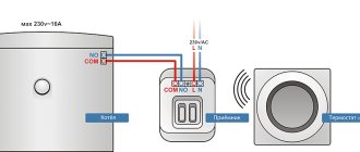
Connection diagram of the circulation pump to the electrical network
The connection diagram for the circulation pump to the electrical network is as follows:
Note. the pump connection diagram must contain either a differential circuit breaker (as in our diagram) or a combination of a protective circuit breaker and an RCD (Residual Current Device)
This is required, first of all, to protect a person from electric shock in the event of a pump malfunction or incorrect connection.
As you can see, there is nothing complicated in the circuit; to operate, a household circulation pump requires a phase and a zero (working zero), and in addition, an indispensable safety element is grounding (protective zero). Therefore, there are three contacts in the pump terminal box, with corresponding markings.
Detailed photo instructions for connecting the circulation pump to the electrical network, according to this diagram - HERE (link will open in a new window).
Most circulation pumps in heating systems are connected according to this standard scheme. The main disadvantage of which is that the pumps have to be turned on and off manually each time, so they are often turned on at the beginning of the heating season and turned off at the end. Disadvantages of this connection method. I think it is obvious that there is excess energy consumption and a decrease in the service life of the pump.
You can automate the operation of the circulation pump in the heating system in order to reduce energy costs and increase the overall service life of the pump by connecting it through a thermostat.
At the same time, the thermostat measures the temperature of the coolant and, if it is low, the circulation pump does not turn on, so as not to waste cold water (or other coolant) through the system, and when the temperature of the coolant at the boiler reaches the required level, the pump starts.
What wire can be used to connect room thermostats?
Another important point in connecting the thermostat is the choice of wire. Typically, the cross-section and number of cores are indicated in the instructions for a specific product. In addition, you need to remember the distance from the thermostat to the boiler or hub to which the thermostat is connected - if the output on the thermostat is potential, then the length of the wire can have a significant impact on the operation of the automation. This is due to the voltage drop on the wire. To reduce it, you should take a wire with the largest possible cross-section.
Most often, to connect mechanical thermostats, a two-core wire with a cross-section of 0.5 or 0.75 “squares” is used . For electronic ones, as I described above, it is important to consider the length of the wire. The longer the wire, the larger the cross-section should be (usually the cross-section does not exceed 1.5 “squares”) . But manufacturers do not recommend exceeding the wire length of 100 meters, although this is not specified in the data sheets and instructions for the products.
Operating principle
The operating principles of thermostats differ: for example, flow-through thermostats only block access to the coolant into the radiator circuit, while three- and four-way thermostats mix heated liquid with cooled liquid. Each thermostat has its own advantages and disadvantages. The installation of this device should be based on its operational characteristics.
In 1994, when construction companies, in accordance with the new SNiP, were required to equip heating systems with thermoregulating elements, only one enterprise in Kazan was engaged in the production of such devices. Today there are dozens of such manufacturers.
Mechanical models
The valve and thermal head are the main elements, without which it is impossible to imagine almost any thermostat. In this case, the latter performs the function of a sensitive element. These parts do not require external energy in order to function properly.
In turn, the thermal head also has several components. This is a regulator and drive, a liquid element, sometimes elastic or gas parts are found as an alternative.
Internal organization
When choosing a temperature controller, it is necessary to take into account all factors that may affect the operation of the device in the future. Its main parts are as follows:
- adjustable scale;
- ring that fixes the set temperature;
- mechanism of compensatory action;
- union nut;
- stock;
- spool;
- detachable connection;
- sensing element;
- thermostatic element;
- thermostatic valve.
Two-way thermostats
The operating principle of these devices differs significantly from those described above. They are the same valve, only with two pipes - for connecting to the radiator and the coolant supply pipe. In this case, no mixing of coolants occurs. The temperature is reduced by shutting off the hot water supply in the circuit.
But can such devices be classified as thermostats? Most likely it is possible. Let's look at the design of a simple mechanical device.
It resembles a mechanical thermostat, but the liquid filler can be replaced with gas or spring filler. In both cases, the efficiency of responding to temperature changes is sharply reduced. But still this is a reaction without the presence of a person. In this design, the main move is to shut off the main coolant supply circuit and reduce its speed. This is precisely what the work of such a mechanism is based on.
DIY thermostat: diagram
About the design of the thermostat, we can say that it is not particularly complicated, it is for this reason that most radio amateurs begin their training with this device, and also hone their skills and craftsmanship on it. You can find a very large number of device circuits, but the most common is a circuit using a so-called comparator.
This element has several inputs and outputs:
- One input responds by supplying a reference voltage that corresponds to the required temperature;
- The second receives voltage from the temperature sensor.
The comparator itself receives all incoming readings and compares them. If it generates a signal at the output, it will turn on the relay, which will supply current to the heating or refrigerating unit.
Materials used in the production of circulation pumps
This is a very important aspect that affects not only the quality of work, but also the cost of the unit. It is clear without words that contact of pump parts and assemblies with water brings a lot of trouble. Therefore, for the production of this type, high-strength materials are used that can withstand water with a fairly high temperature.
For example, today analogs are produced where the shaft, that is, the rotor, and bearings are made of ceramics. Such parts have high strength and a long service life. In addition, ceramics are not afraid of water. Plus, such parts work silently.
The average guaranteed service life of circulation pumps is at least ten years. Of course, the manufacturers' requirements here must be strictly followed, otherwise there are no guarantees. What do manufacturers require? Correct selection, correct installation, prepared coolant, preventing some negative indicators in the heating system, for example, air inside.
Homemade thermostat: step-by-step instructions
If you have purchased all the necessary components for assembly, all that remains is to review the detailed instructions. We will consider the example of a temperature sensor designed for 12V.
A homemade temperature controller is assembled according to the following principle:
- We prepare the body. You can use old shells from the meter, for example from the Granit-1 installation.
- You select the circuit that you like best, but you can also focus on the board from the meter. The forward stroke marked “+” is necessary to connect the potentiometer. The inversion input with o will be used to connect the temperature sensor. If it so happens that the voltage at the direct input is higher than required, the output will be set to a high level and the transistor will begin to supply power to the relay, and it, in turn, to the heating element. As soon as the output voltage exceeds the permissible level, the relay will turn off.
- In order for the thermostat to operate on time and temperature differences to be ensured, you will need to make a negative connection using a resistor, which is formed between the direct input and output of the comparator.
- As for the transformer and its power supply, you may need an induction coil from an old electric meter. In order for the voltage to correspond to 12 volts, you will need to make 540 turns. It will only be possible to fit them if the diameter of the wire is no more than 0.4 mm.
That's all. These small steps are where all the work of creating a thermostat with your own hands lies. It may not be possible to do it yourself without certain skills right away, but with the help of photo and video instructions you will be able to test all your skills.
Thanks to its simple design, a self-created thermal controller can be used anywhere.
- For heated floors;
- For the cellar;
- Heating boiler;
- Can adjust air temperature;
- For the oven;
- For an aquarium where the water temperature will be controlled;
- In order to control the temperature value of the electric boiler pump (its switching on and off);
- And even for a car.
It is not necessary to use a digital, electronic or mechanical commercial thermal switch. Having bought an inexpensive thermal relay, adjust the power on the triac and thermocouple and your homemade device will work no worse than the purchased one.
Circulation pump connection
If the pump was not previously included in the heating system. it is required to be “inserted” into the pipeline. Since this operation requires the performer to have some skills and the presence of special equipment, it can be entrusted to professionals, or you can do the work yourself, having previously familiarized yourself with the technology of pipeline installation. The order of work and the list of equipment used will depend on the selected insertion method and pipeline material.
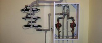
There are 2 ways to insert a circulation pump:
- on the main section of the pipeline;
- on the bypass section (bypass).
Installing the unit on the main site requires less time and money, but has one significant drawback. The pump operates from the mains power supply, so with this installation method, during a power outage in the apartment or house, the heating will not be able to function.
The second method is more complex, but provides the heating system with an increased level of autonomy. In this case, when the system operates in normal mode, the coolant moves through the bypass channel, and the corresponding section of the main line is closed using a specially installed ball valve. During a power outage, the faucet opens and liquid moves through the pipeline naturally.
Installation diagram of the pump on the bypass channel (bypass).
Although this option is common, it has one big drawback - the tap is on the main line. It is better if a ball valve is installed instead of a tap.
Installation of a pump on the supply of a gas floor boiler in a heating system with natural circulation. An article on the topic “How to choose a gas boiler” may be useful to you.
During normal operation, the valve is closed by excess pressure created by the pump above the ball. If the pump is de-energized, the ball rises under the pressure of water moving naturally along the line. This option is relevant if the pump is installed on the “supply” side for one reason or another.
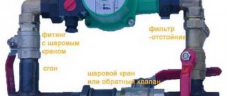
Pump tap-in installation kit includes:
- pipes of the required diameter;
- elements of pipeline fittings;
- union nuts (for polypropylene pipelines) or bends (for steel pipes);
- dirt filter;
- shut-off valves;
- check valve
The diameter of the pipes for tapping must correspond to the diameter of the already installed pipeline, and their total length is determined based on the results of measurements in the area where the pump is intended to be installed. A set of pipeline fittings is selected in the same way. Union nuts (or clamps) are used for quick installation and removal of the pump.
The dirt filter is installed directly before the entrance to the unit. It is necessary to protect the pump from contamination, the source of which may be deposits on the inner surface of the pipelines. The drainage hole of the filter should be directed downward to allow periodic cleaning.
Shut-off valves are placed at the inlet of the pump in front of the filter and at the outlet of it so that, if necessary, the unit can be dismantled without stopping the entire system. When installing a supercharger in a bypass section, an additional valve is installed on the main line parallel to the pump. The check valve is designed to protect the system from water hammer. It is mounted at the outlet of the pump in front of the shut-off valve.
Tip 3 How to connect heated floors to the boiler
The most economical and convenient option for heated floors is water floors with a connection to the boiler
. This system allows you to save a large amount of energy and makes it possible to independently regulate the heating temperature. In addition, it is easier to install.
- — wall-mounted boiler for heated floors;
- - collector cabinet;
- — shut-off valves;
- — compression fittings;
- - circulation pump;
- — thermostat (preferably, although not required).
Install heated floors in a sand-cement screed. To do this, prepare all the system components. Remove the existing screed and distribute all the elements of heated floors over the area where they are planned to be installed.
Then hang the boiler for heated floors in a convenient place - so that the loops of water pipes come from the collector. If you are installing floors in your own home, then it is advisable to place the equipment in a specially designated room. Regarding the installation of a boiler in an apartment, it is better to consult with an experienced technician.
Install the manifold cabinet. Its task is to circulate water in the pipes and combine floor heating with other home heating.
Place the supply and return pipes into the installed manifold cabinet. The first will supply hot water to the water floors. the second is to take the cooled liquid and return it back to the boiler. Install a shut-off valve on each pipe so that you can turn off the water if necessary.
Using a compression fitting, connect the pipe from the boiler to a metal valve, and connect the manifold inlet to the valve. Use fittings to connect the heated floor contours to the manifold.
Install a circulation pump in the collector designed to continuously circulate water. It is mounted on the supply pipe. It is better to purchase a pump with a thermostat. which will allow you to regulate the temperature of the floor heating.
After this, turn on the system and check its operation.
The final installation of heated floors is carried out only after the operation of the heating system has been checked. It should function for at least 10-12 hours. And, if everything is in order, the floor surface is laid over the pipes. Otherwise, there is a risk of flooding your own home due to a minor mistake. If the pipes are laid in a sand-cement screed, the system can be turned on only after the solution has completely hardened.
To avoid problems with connecting many different control devices, you can purchase a pump mixing circuit for wall-mounted boilers, which includes a circulation pump and almost the entire set of equipment.
- Installation of water heated floor
- how to connect a heated floor
Power connection
The circulation pumps operate from a 220 V network. The connection is standard; a separate power supply line with a circuit breaker is desirable. The connection requires three wires - phase, neutral and ground.
Circulation pump electrical connection diagram
The connection to the network itself can be organized using a three-pin socket and plug. This connection method is used if the pump comes with a connected power wire. It can also be connected via a terminal block or directly with a cable to the terminals.
The terminals are located under a plastic cover. We remove it by unscrewing several bolts and find three connectors. They are usually labeled (the pictograms are N - neutral wire, L - phase, and “ground” has an international designation), so it’s hard to make a mistake.
Where to connect the power cable
Since the entire system depends on the performance of the circulation pump, it makes sense to make a backup power supply - install a stabilizer with connected batteries. With such a power supply system, everything will work for several days, since the pump itself and the boiler automation “pulls” electricity to a maximum of 250-300 W. But when organizing, you need to calculate everything and select the battery capacity. The disadvantage of such a system is the need to ensure that the batteries do not discharge.
How to connect a circulator to electricity through a stabilizer
Hello. My situation, a 25 x 60 pump is located immediately after a 6 kW electric boiler, then the line from a 40 mm pipe goes to the bathhouse (there are three steel radiators) and returns to the boiler; after the pump, a branch goes up, then 4 m, down, rings a house of 50 sq. m. m. through the kitchen, then through the bedroom, where it doubles, then the hall, where it triples and flows into the boiler return; in the bathhouse there is a branch 40 mm up, it leaves the bathhouse and enters the 2nd floor of a house of 40 sq. m. m. (there are two cast-iron radiators) and returns to the bathhouse in the return line; there was no heat on the second floor; the idea of installing a second pump in the bathhouse for supply after the branch; the total length of the pipeline is 125 m. How correct is the solution?
The idea is correct - the route is too long for one pump.
What is a circulation pump and why is it needed?
A circulation pump is a device that changes the speed of movement of a liquid medium without changing pressure. In heating systems it is installed for more efficient heating. In systems with forced circulation it is a mandatory element, in gravity systems it can be installed if it is necessary to increase the thermal power. Installing a circulation pump with several speeds makes it possible to change the amount of heat transferred depending on the outside temperature, thus maintaining a stable temperature in the room.
Cross-section of a circulation pump with a wet rotor
There are two types of such units - with a dry and wet rotor. Devices with a dry rotor have a high efficiency (about 80%), but are very noisy and require regular maintenance. Units with a wet rotor operate almost silently; with normal coolant quality, they can pump water without failure for more than 10 years. They have a lower efficiency (about 50%), but their characteristics are more than sufficient for heating any private home.
DS18S20
Update September 15, 2015. Added firmware for a two-speed pump
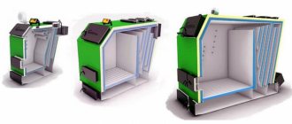
Update September 10, 2015. Added firmware for pic16F628A microcontroller
The device was initially assembled on a pic16f84a (pic16f628a) microcontroller. The DS1820 (DS18S20) sensor measures the temperature of the pipe at the boiler outlet. Depending on the temperature, the microcontroller turns the circulation pump on or off. Its main task is to turn on the circulation pump when the pipe is hot and turn it off when the pipe is cool.
To speed up the heating of the heating system when starting the boiler while the pipe is cold, by pressing the button you can switch the controller to manual mode for half an hour. In this case, the pump turns on when the pipe is cold. If the pipe does not warm up within half an hour, the controller goes into normal mode, turning off the pump.
When the temperature goes beyond the specified limits (less than +6 and more than +68 degrees), the controller sounds a sound signal and lights up the red LED. If the sensor breaks, a sound signal also sounds and the red LED lights up.
Simplified and schematically, this can be depicted as follows:
More information about the indication: LED1:
(temperature)
- off – temperature between 7 and 39
- green – temperature between 39 and 69
- yellow – temperature >69 or 6°C)
- 44H (68 => 34°C)
- 88H (136 => 68°C)
If you need to set other temperature thresholds, then you need to change these values. For example, you need to set the thresholds to 12, 45 and 75°C.
- 12 => 12*2=24 => 18H
- 45 => 45*2=90 => 5AH
- 75 => 75*2=150 => 96H
Thus, new values 18H, 5AH and 96H must be entered into the EEPROM cells before flashing.
Update:
In v2.2, the ability to select the temperature sensor type DS1820 or DS18B20 by setting the Jmp1 jumper has been added.
In final assembled form. The building cost half a kingdom.
Printed circuit board
Schematic diagram of switching on a two-speed pump. Nothing fundamentally changed in the basic design. A second node has been added (circled with a dotted line) to connect the high speed output of the pump. According to the logic of the controller’s operation, the second triac unit is turned on in the rapid heating mode. In normal mode, the second node is disabled and the first is enabled.
This scheme corresponds to firmware version 2.2.2
.
Firmware v2.2.2 has not been tested on a real device
Firmware
Version 2.2.2 for two-speed pump
Fuse configuration for pic16f628a 0x3FE9
In version 2.2.1, a bug in selecting a temperature sensor has been fixed. Firmware is available for two microcontrollers:
Fuse configuration for pic16f628a 0x3FE9
Version 2.2 added the ability to select a DS1820 or DS18B20 temperature sensor. DS18B20 is selected by installing jumper Jmp1. The firmware has not been tested in hardware. Subscribe, who will check.
Version 2.1 added the ability to set your own temperature values when flashing the firmware.
Version 2.0 fixed a small bug that only appeared when the temperature sensor was broken.
Varieties
Depending on the design, thermostats come with a built-in or remote sensor. The latter are convenient because they allow you to place the thermoelement and the control knob at a considerable distance from each other.
Classification by number of pipes
Based on the number of connected radiator pipes, they are divided into two-way, three-way and four-way. Two-way thermostats are also called walk-through thermostats. They have two outlets and are attached to only one pipe. A two-way regulator has a mechanical or electrical valve that partially or completely blocks the flow of coolant.
Heating systems equipped with three-way thermostats have great potential. The latter not only block access to hot water, but also supply cold water to the radiator circuit. As a result of mixing flows, the heating temperature of heating devices decreases.
It is important to install the three-way thermostat correctly. The manufacturer usually depicts the installation diagram on the device body
Blue color indicates the place for connecting the supply pipe with cooled coolant, red – with heated coolant, and the outlet location is marked with an arrow. The same applies to four-way models. True, unlike three-way regulators, they are capable of maintaining recirculation of cooled and heated coolants without mixing.
Classification by type of actuation
Depending on the method of actuation, thermostats are divided into two categories - manual and automatic. With the first ones, everything is simple: to reduce the flow of heated water or block its path into the radiator circuit, you need to turn the knob.
The second ones have a more complex design. They consist of a sensor and a thermostatic element built into a plastic housing. The sensor is filled with gas condensate, water or wax, which, when heated to a certain temperature, changes the volume of the medium. After this, the rod of the device begins to move, partially or completely closing the mechanical valve.
You can also install an electronic thermostat. It is equipped with an electrically operated valve. Depending on the principle of operation, electronic devices are:
- automated, which are triggered when the temperature recorded by the sensor changes;
- programmable, triggered in a user-specified period of time;
- radio-controlled, when the temperature of the heating radiator is controlled using a remote control.
Accurate thermometer
The use of semiconductor diodes and transistors as sensors is characterized by the difficulty of calibrating readings, which ultimately leads to an error in the measurement result. Therefore, to obtain an accurate result, a bifilar wound coil of thin conductor, placed in a cylinder with dimensions of about 4 × 20 mm, is used as a meter.
The basis of the design is the ICL707 chip and a glowing indicator. Power can be supplied from any source with an output amplitude of 12 V. The DA3 contains a normalizing converter that changes its output voltage depending on the signal received from the sensor.
The setting consists of setting the voltage on the 36th leg of the microcircuit to one volt. This is done using resistors R3 and R4. Instead of the sensor, a 100 Ohm resistor is connected. By changing resistance R14, zeros are set on the digital indicator. After which the device is ready for measurements.
Maintaining temperature conditions is a very important technological condition not only in production, but also in everyday life. Having such great importance, this parameter must be regulated and controlled somehow. They produce a huge number of such devices, which have many features and parameters. But making a thermostat with your own hands is sometimes much more profitable than buying a ready-made factory analogue.
Source of the article: https://radiator-lammin.ru/remont-i-montazh/prostoj-termoregulyator-svoimi-rukami-shema.html
What is a circulation pump
This is a small unit that is installed in the heating pipeline system and distils the coolant through all branches of the heating system, that is, it ensures the circulation of hot water. There is a wide variety of circulation pumps for heating systems. but for private houses, units with the so-called “wet rotor” are usually used. What is the design feature of this model?
The thing is that the moving parts of the pump, and this is mainly the rotor and impeller, are cooled and at the same time lubricated by the liquid flowing inside the pump, that is, the coolant. Hence the quiet operation, high reliability, and small dimensions of the unit itself. Let's add durability, efficiency and cost-effectiveness here.
Advantages
Thermostats can reduce thermal energy costs by 10-20%. Those systems that not only have individual thermostats, but are also additionally equipped with regulators at the heating source, save 25-35% of thermal energy.
In addition, a pleasant microclimate is constantly maintained in the room, especially if automation is used to control the coolant.
Additional benefits
Other benefits of using temperature control devices include versatility and high accuracy. The versatility lies in the fact that thermostats are suitable for installation in heating systems of any type.
This equipment is used with gas, electric and solid fuel boilers.
High accuracy of adjustment is manifested in the fact that even a mechanical device stops the supply of heated water to the battery at the correctly calculated moment, not to mention devices with electronic filling.
The latter can be configured in such a way as to maintain a specific, comfortable temperature at certain hours. Often, an electronic thermostat even has a weekly programming function. The advantages also include the following qualities:
- durability - devices are made of corrosion-resistant steel. Particularly interesting is Russian-made equipment, which in terms of hydraulic and strength properties corresponds to domestic realities;
- a wide range of brands and models - today thermostats are manufactured by many companies and supplied from abroad. High competition allows you to reduce the cost of products.
Automatic room heat regulation
What is it for
- The most common on the territory of the Russian Federation is centralized heating or autonomous heating, using gas boilers. But such, so to speak, luxury is not available in all areas and localities. The reasons for this are the most banal - the lack of thermal power plants or central boiler houses, as well as gas mains nearby.
- Have you ever visited a residential building, pumping station or weather station remote from densely populated areas in winter, when the only means of communication is a sleigh with a diesel engine? In such situations, very often they arrange heating with their own hands using electricity.
Autonomous heating with electricity using EOU
- For small rooms, for example, one room for the person on duty at a pumping station, an oil heating radiator - it will be enough for the harshest winter, but for a larger area a heating boiler and a radiator system will be required. To maintain the desired temperature in the boiler, we bring to your attention a homemade control device.
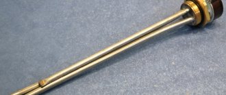
Temperature sensor
- This design does not require thermistors or various sensors such as TCM ; instead, an ordinary bipolar transistor is used here. Like all semiconductor devices, its operation largely depends on the environment, more precisely, on its temperature. As the temperature rises, the collector current increases, and this negatively affects the operation of the amplifier stage - the operating point shifts until the signal is distorted and the transistor simply does not respond to the input signal, that is, it stops working.
- Diodes are also classified as semiconductors , and rising temperatures have a negative effect on them as well. At t25⁰C, the “continuity” of a free silicon diode will show 700 mV, and for a permanent one - about 300 mV, but if the temperature rises, then the forward voltage of the device will decrease accordingly. So, when the temperature increases by 1⁰C, the voltage will decrease by 2mV, that is, -2mV/1⁰C.
- This dependence of semiconductor devices allows them to be used as temperature sensors. The entire operation circuit of the thermostat is based on this negative cascade property with a fixed base current (diagram in the photo above).
- The temperature sensor is mounted on a transistor VT1 type KT835B , the cascade load is resistor R1, and the DC operating mode of the transistor is set by resistors R2 and R3. To ensure that the voltage at the transistor emitter at room temperature is 6.8V, a fixed bias is set by resistor R3.
Advice. For this reason, in the diagram R 3 is marked with * and special accuracy should not be achieved here, as long as there are no large differences. These measurements can be made relative to a transistor collector connected by a power source to a common drive.
- The pnp transistor KT835B is specially selected; its collector is connected to a metal body plate that has a hole for attaching the semiconductor to the radiator. It is through this hole that the device is attached to the plate, to which the underwater wire is also attached.
- The assembled sensor is attached to the heating pipe using metal clamps , and the structure does not need to be isolated from the heating pipe with any gasket. The fact is that the collector is connected by one wire to the power source - this greatly simplifies the entire sensor and makes contact better.
Comparator
Comparator circuit diagram
- A comparator mounted on an operational amplifier OP1 type K140UD608 sets the temperature. The invertible input R5 is supplied with voltage from the emitter VT1, and through R6 the non-invertible input is supplied with voltage from the engine R7.
- This voltage determines the temperature for switching off the load. The upper and lower ranges for setting the threshold for triggering the comparator are set using R8 and R9. The required posteresis of the comparator is provided by R4.
Load management
- on VT2 and Rel1 and the thermostat operating mode indicator is also located here - red when heating, and green when the required temperature has been reached. A diode VD1 is connected in parallel to the Rel1 winding to protect VT2 from voltage caused by self-induction on the Rel1 coil when turned off.
Advice. The figure above shows that the permissible switching current of the relay is 16A, which means it allows control of a load of up to 3 kW. Use a device with a power of 2-2.5 kW to lighten the load.
power unit
Power supply for thermostat
- An arbitrary instruction allows for a real thermostat, due to its low power, to use a cheap Chinese adapter as a power supply. You can also assemble a 12V rectifier yourself, with a circuit current consumption of no more than 200mA. For this purpose, a transformer with a power of up to 5 W and an output of 15 to 17 V is suitable.
- The diode bridge is made using 1N4007 diodes, and the voltage stabilizer is based on an integrated type 7812. Due to the low power, it is not necessary to install a stabilizer on the battery.
Diagram and principle of operation of circulation pumps for heating
Structurally, the unit is a complex of main components and additional elements.
The supercharger circuit includes:
- Frame. Needed to protect the device from external influences.
- Box with terminals. Electrical components and adjustment devices are connected here.
- Electric motor. Puts the equipment into operation.
- Impeller. The part ensures the transportation of liquid through the pipeline at a given speed.
- Transfer chamber. The compartment is equipped with pressure and supply pipes for connection to the heating network circuits.
The principle of operation of the supercharger is simple:
- through the inlet pipe, water enters the pumping chamber;
- the coolant is picked up by the blades of the impeller, which begin to function when the engine is turned on;
- An increase in pressure sets the coolant in motion, water passes through the outlet pipe and enters the heating system line.
The circuit for the heating pump does not have any difficulties; the device works on the same principle as all blowers. The peculiarity lies in the correct choice of device depending on the type of heating network, design characteristics of the main line, boiler and heating devices.
Automatic control unit for circulation pump
The circulation pump is controlled by a thermostat, relay, and uninterruptible power supply. The complex is needed to regulate the heating of the coolant and maintain the operation of the equipment.
Thermostats
The units combine the functions of a thermoelement and a valve; they are needed to adjust the water heating temperature.
The thermostat for the heating circulation pump works like this:
- Reads information from the temperature sensor. Compares indicators with settings. To set the settings mode, there is a side menu with a difference between the pump start temperature and hysteresis. Hysteresis is the time interval of temperature lag when the heater is turned on and off.
- When the equipment is started, hysteresis is automatically added to the water heating indicator when the blower is turned on. When the pump is turned off, the hysteresis is subtracted from the total value.
By default, the hysteresis size is taken to be 1/10 of the coolant heating temperature. Thus, when the water is heated at +50 C, the hysteresis is only 5 degrees. For the automatic control unit to start working, the water must warm up to +55 C. To turn off the unit, it must cool to +45 C. Units with hysteresis are more convenient to use. The equipment maintains a temperature rise of 5 degrees, therefore it is protected from constant switching on/off.
The thermostat should be selected with a firmware hysteresis of at least +/- 1 degree, maximum +/- 10 degrees. Place a thermostat next to the boiler. Provided that it is adjusted taking into account the external temperature in the room, the boiler adjustment should be able to change the media indicator.
Uninterruptible power supply
The heating circulation pump control unit is a volatile equipment and will not work without electricity. A UPS (uninterruptible power supply) or generator will eliminate the possibility of downtime. It is permissible to do without a power supply device, starting the network in gravity mode. But there is a risk of errors in pipeline layout, which will lead to network failure.
The contours of the gravity heating network, according to the laying technique, are inclined towards the return circulation pipe. It is recommended to maintain the slope within 3 cm for each meter of pipeline. This requires accurate calculations of the circuit and increases the network layout area.
The return circulation line is mounted with a slope towards the heater, also taking into account the slope. If the level of reduction is small, there is a risk of coolant stagnation and the formation of an air lock. In addition, the heater should be installed at the lowest point of the circuit, which causes difficulties in the absence of a basement.
A circulation pump will help to avoid all problems; to provide it with power, a UPS or generator is built into the network. The choice depends on the user, but the generator makes a lot of noise during operation, while the uninterruptible power supply operates as quietly as possible.
On/off relay
This is a module for starting equipment into operation and turning off the unit. The heating pump activation relay is an important component responsible for maintaining the functionality of the entire unit.
The task of the unit is simple:
- a decrease in the pressure level in the network is a signal to start the device into operation, the relay turns on the equipment;
- exceeding the established pressure norm is a signal to stop the equipment.
Thus, when the coolant collection stops and the pressure in the network increases, the timer for the heating pump switches off. Resuming the extraction of hot water leads to a decrease in the pressure indicator and puts the device into operation. Whether or not to install a thermostat or UPS is up to the owner.
A high-quality circulation pump with a temperature sensor has a number of advantages:
- reduces fuel consumption;
- ensures maintenance of a comfortable temperature in the premises;
- makes it possible to quickly adjust the operating mode.
Experts recommend choosing devices in accordance with the manufacturers' instructions. Manufacturers of equipment without an automatic control unit indicate in the technical data sheet the parameters of the unit suitable for installation on the devices.
To simplify the regulation of water flow in the battery, it is recommended to equip all batteries in the house with thermostats. When choosing them, you need to take into account the gradations of the settings - the smaller the divisions, the more accurate the mode. It is more practical to take devices with a scale gradation of up to 5 degrees.
How to make a thermostat for heating with your own hands
Among the numerous assortment of useful devices that bring comfort to our lives, there are a large number of those that you can make with your own hands. This number also includes a thermostat, which turns heating and cooling equipment on or off in accordance with the specific temperature at which it is set. This device is perfect for periods of cold weather, for example for a basement where you need to store vegetables. So how to make a thermostat with your own hands, and what parts will be needed for this?
Functional purpose of thermostats
In most cases, during heating operation, uneven heat distribution in radiators and pipes is observed. This is due to its cooling while moving along transport routes. For stabilization and timely adjustment, room thermostats for heating are installed.
Controlling the degree of heating of the radiator. By regulating the flow of hot water, the temperature on the surface of the heating device changes;
Optimization of coolant heating costs. An overhead thermostat for heating reduces the cost of heating hot water by reducing the difference in coolant temperature between the supply and return pipes;
Automation of heating operation. Almost all models of temperature control devices operate autonomously
It is important to initially correctly set the initial operating parameters.
How does a thermostat for a heating boiler differ from a similar model for a radiator or circulation pump? First of all, the response speed of the control element and the operating temperature. Therefore, it is recommended to select the optimal model for each heating component. And to do this, you should consider their types and design features.
Any thermostat for heating a home has individual operating parameters - installation features, degree of temperature control, etc. They must correspond to the characteristics of the heating element on which the device will be installed.
Open logic
There are also freely programmable types of devices with open logic. They are also often found in circulation-type pumping products. Such devices can be easily adjusted to any environmental conditions and temperature conditions.
But managing them is quite difficult; special qualifications are required. That is why they are not widely used; in circulation-type devices, closed logic is most often found.
You should not save on purchasing a thermostat for your heating system, because this product significantly increases productivity and efficiency.
Source
Installation of a thermostat
Before installing the thermostat, you need to make sure that it is compatible with the heating system. Each device has its own valve capacity coefficients, denoted Kv and Kvs.
It is recommended to equip single-pipe systems with thermostats with a Kv value greater than 1, and even better - greater than 1.5. For two-pipe regulators, regulators with Kv in the range from 0.5 to 0.9% are more suitable.
Sequence of work
The sequence of installation work is as follows:
- after shutting off the supply riser, water is drained from the heating system;
- horizontal pipe connections are cut off at a short distance from the battery;
- disconnect the cut section of the pipeline along with the valves;
- if the system is single-pipe, a bypass is welded. This is a jumper that will allow coolant to circulate through the circuit when the valves are closed and there is no access to the battery. In two-pipe heating systems, the thermostat is mounted on the upper supply pipe, and the valve is mounted on the lower;
- remove the shanks with nuts from the shut-off valve and thermostat, and then screw them into the radiator plugs;
- The piping is assembled and installed, and then connected to the horizontal supply pipes.
Location nuances
The axis of the thermal head should always be located in a horizontal position so that the temperature measurement accuracy of the device is high.
In a vertical position, the sensor will be exposed to rising and falling heat flows, causing temperature readings to be incorrect.
If the rod axis is mounted vertically, it is better to use a remote electronic sensor with an electric drive or with radio signal transmission.
Thermostats that have a built-in sensor must be positioned so that they are visible, but not within the range of operation of heating devices. Also note that heat is shielded by thick curtains. The optimal height for placing the thermostat is at least 80 cm from the floor surface.
It is allowed to install thermostats on bimetallic, steel and aluminum batteries. If the radiator body is cast from cast iron, it is not recommended to install a thermostat due to the high inertness of this alloy.
About installation and its features
A thermostatic type valve is installed on the supply part of the regulator pipeline. It is important to maintain a horizontal position for the heating device head. Exposure to direct sunlight and heat in large quantities is unacceptable.
Radiators cannot perform their functions properly if they are covered with curtains or crowded with furniture. In such a situation, a zone with an almost complete lack of sensitivity appears. This means that there is no contact with the environment.
Otherwise
If it is impossible to install the heating system in any other way, you will have to use remote control sensors that have a sensitive overlay element. So-called mini heating regulators are also designed for installation in niches.
Experts recommend installing a special shut-off valve on the return line of the heating radiator. Then you will not have to disconnect the entire heating system from the riser if you need to clean the battery or dismantle it.
The pump thermostat must be fully opened when the heating season ends. After this, no excess sediment will form on the valve seat; the device itself simply turns counterclockwise.
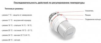
There are several thermal modes with which different types of pump devices can operate.
- summer - 28 °C;
- bathroom - 24 °C;
- living room - 20 °C;
- bedroom - 16 °C;
- internal corridor - 11 °C;
- frost protection - 7 °C.
It is necessary to adjust the thermostat for the pump before starting active operation. At this stage, additional hydraulic resistance is created. It is necessary to smoothly adjust the throttle mechanism to achieve the desired result of the pump.
The battery check valve and the battery inlet valve are equally good at accomplishing this same task.