Overheating of the coolant leads to its strong expansion, especially if the temperature has reached the boiling point. When the coolant expands, the pressure in the system rises, which can lead to serious consequences: from slight leakage of connections or failure of heating system components, to rupture of lines in inaccessible places (walls or under floor screed).
A well-known way to prevent the destruction of a heating system due to high pressure is a safety relief valve. In the article we will look in detail at its design and operating principle, define the criteria for choosing a mechanism, the installation algorithm in the heating system, as well as actions in a situation if the pressure relief valve has leaked.
Why might a valve leak?
The pressure relief valve in the heating system can leak for various reasons.
In some situations, this is an acceptable natural process; in other cases, a leak indicates a malfunction of the device. Leakage of the protection valve can be caused by the following reasons:
- Damage to the sealed rubber cup or disc as a result of repeated use. If during repairs a replacement part cannot be found on sale or is not included in the package, you will have to replace the device completely.
- In spring types, the opening of the side drain pipe occurs gradually; at borderline pressure values or short-term surges, the valve may partially operate and drip, which does not indicate its malfunction.
- Leakage can be caused by incorrect settings or malfunctions of the expansion tank - damage to its membrane, air escaping through a depressurized housing or a damaged nipple. In this case, sharp pressure surges are possible as a result of water hammer, causing periodic short-term leakage of coolant through the safety valve.
- The cause of leakage in some adjustable valves is fluid seeping down the stem through the top during actuation.
- If a back pressure is created at the outlet pipe above the device's response threshold, a leak will also occur.
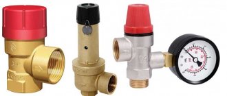
Appearance, cost of some brands of drain valves
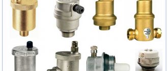
The safety valve of steam boilers is designed to protect them from excess pressure in the system caused by various factors, and is a mandatory element when operating this type of equipment. There is a wide range of safety devices on sale from Chinese, domestic and European manufacturers, which are characterized by a relatively low cost. When purchasing, it is rational to choose a protective group from several devices, which additionally includes a pressure gauge and an air release valve.
How to install
When installing safety drain fittings, observe the following rules:
- Typically, a pressure relief valve in a heating system is installed in a household circuit in a single copy. Its main placement points are directly above the electric, solid fuel, gas boiler on its outlet pipe or nearby in a horizontal pipeline. If this is not possible for technical reasons, the main condition for correct installation is installation in the supply line up to the first shut-off valve.
- The side outlet pipe is usually connected to a sewer or drainage system; if this is technically difficult or the volume of coolant in the circuit is low, you can use a flexible line, which is lowered into a container of suitable volume.
- The liquid must be drained with a stream breaking through a funnel or hydraulic valve to ensure the system is operational when the sewer is clogged.
- When installing in a pipeline, use a tee with a bottom outlet of a suitable diameter, its standard value is 1/2, 3/4, 1 and 2 inches. The diameter of the pipeline supplying the valve should not be less than that of the system.
Safety valve groups - types and price
Design features and operation
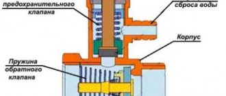
Consider in detail how a safety valve with a spring works. Its body is made using hot stamping technology from brass. The main working element is a spring, which presses the membrane that covers the seat.
Valve with spring mechanism
On the rod connected to the handle there is a washer that serves as a stop for the upper end of the spring. Using the handle, the position of the washer and, accordingly, the clamping force on the membrane are changed. The spring is made of steel; the handle, seals and membrane are made of polymer materials.
The operating principle of the device is as follows: as long as the parameters of the coolant do not exceed the specified maximum permissible values, the membrane tightly closes the hole. When the situation is close to an emergency, as the pressure increases, the superheated coolant (a mixture of water and steam) lifts the membrane, overcoming the resistance of the spring. Thanks to this, the steam-water mixture is discharged out through a special hole. After dumping the excess volume of the steam-water mixture, the pressure in the pipeline decreases, and the coolant again loses the ability to compress the spring.
Note! The device can operate cyclically if the boiler is operated at maximum power, heating the coolant to 90-95 degrees. This mode of operation has a negative impact on the protective device - after several operations the blast valve begins to leak due to loss of tightness
Design
A typical safety valve for a boiler has a collapsible design and consists of the following main elements:
Frame . Usually made of brass and shaped like a tee. On its sides there is a lower inlet threaded hole, a side outlet pipe and an upper seat on which the shaped seal is seated.
Locking group . It is a spring-loaded pulley with a cylindrical (disc) end locking element, onto which an elastic rubber seal in the form of a cup (disc) is placed.
Lid . A black cap made of heat-resistant polymer is screwed into the upper threaded pipe of the brass body, holding the spring-loaded rod in the working position. On the upper edges of the lid there are protrusions along which the upper cap, shaped at the bottom, slides, connected to the locking rod. When turned to a certain angle, the cap rises along with the rod and opens the side pipe - this allows you to use the safety valve for heating always open in manual mode.
Cap. The polymer part is usually red in color with a ribbed side surface, and is screwed to the hollow inside of the rod with a screw. The gentle protrusions at the bottom of the cap, when rotated, fall on the teeth of the lid - the handle rises along with the spring-loaded shutter and opens the side channel, allowing you to relieve pressure manually.
Adjusting washer . The inner wall of the cover has a thread in which the adjustment nut rotates; when lowered down, it compresses the spring - thus increasing the valve response threshold. When the nut is unscrewed upward, the spring weakens and the actuation pressure decreases. For turning, the nut is equipped with a transverse slot in the upper part for a flat-head screwdriver.
Valve for water heating boilers - design and appearance
Safety valve
The name of the device speaks for itself. Its main function is to relieve unexpected loads that may arise under certain circumstances. Plus additionally adjustable coolant flow.
By the way, it can be installed on any section of the pipeline
In this case, it is not the location that is important, but the ease of maintenance if such a need suddenly arises
Types of safety valves
- The simplest option is clutch fuses made of brass. Their design is simple - threads are cut on both sides, and the valve is a spring-loaded rod with an EPDM gasket. This is a direct-flow model, the valve of which opens under the pressure of the coolant flow. Back pressure is blocking the line. This is one of the cheapest devices, but it lasts a very long time, which is time-tested.
- There is another brass option, but with a more complex design, where the pipes are connected in perpendicular planes. It uses a stainless steel rod and spring. Install it directly after the circulation pump. The operating principle of such a device is quite simple. The coolant pressure compresses the spring, which begins to put pressure on the rod. It opens a channel through which the coolant is squeezed out of the system, saving it from ruptures of pipes and other elements. By the way, the maximum temperature that the valve can withstand is 120C.
- There are a large number of varieties of check valves, which are also included in the safety group. Their main function is to prevent a counterflow of coolant from occurring if the pressure in the system suddenly drops.
There are several main types - disk, ball, flag and others. But they are all divided into spring-loaded and springless. With the first, everything is clear - there the main emphasis is on the counterforce of the spring. The second type is when the locking element returns under the influence of its own mass.
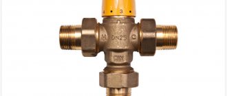
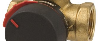
Three way valves. This type of shut-off valve is installed in heating systems where low-temperature circuits are provided. For example, when the circuit has a condensing boiler. Currently, manufacturers produce this type of valve with manual switching or electric switching. In the second case, it is necessary to connect the device to an alternating current network with a voltage of 220 volts.
Three way valves
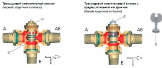
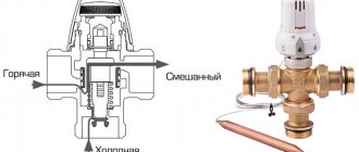
Let's take a closer look at three-way valves, because consumers rarely encounter them, and many are simply unknown to them. Their design has three holes - two output and one input. The coolant flow is regulated by a damper, which can be in the form of a rod or a ball. The rotational motion redistributes the flow of moving fluid.
We have already mentioned condensing boilers, but three-way valves are not only used in these systems. Very often they are used when different heating systems operate from one heating boiler. For example, “warm floors” and ordinary radiators. It is clear that for a warm floor it is not necessary to heat the coolant to a very high temperature. But what if there is only one boiler, and it heats hot water to a standard temperature for the entire system?
In this case, the three-way valve performs several functions at once:
- First, it separates the areas.
- Secondly, it differentiates the flow density along the branches.
- Thirdly, it helps to mix the coolant from the supply and return lines before the latter is supplied to the “warm floor” heating system. That is, water will flow into the floor heating at a lower temperature than to the radiators.
A few recommendations. Take a model with a servo drive. This will save you from the need to constantly monitor the coolant temperature. Such a device is automatic and operates from a sensor mounted in a low-temperature circuit. A change in temperature triggers the shut-off device, which opens or closes the water supply from the return line. So it's simple.
And one last thing. The servomotor may be included with the valve or sold as a separate item. The valves themselves are made of steel, cast iron or brass. The latter are used in residential heating systems.
Mounting options
To ensure reliable and safe operation of the valve in the heating system, it is recommended that installation be carried out in accordance with all rules. You can find them in special regulatory documentation. The rules differ depending on the power and operating pressure of the system. But the basic principles still remain, including:
- In a heating system, this device must be installed on the supply pipe directly after the boiler. If the power of the heat generator is high, it is possible to install two valves.
- The safety valve on the return pipe of heating systems is installed only to ensure hot water supply at the highest point of the boiler.
- It is also unacceptable to narrow the channel in places between the main line and the valve, and the installation of shut-off valves is unacceptable.
- Discharge pipes should be discharged into a sewer system or other safe place. The installation of shut-off devices on this line is completely unacceptable.
It is very important to make the right choice of safety valve for the heating system, which will prevent the boiler from boiling and reduce the pressure. For the valve to work correctly, it is necessary:
- Select spring equipment in which the spring will counteract the coolant pressure.
- Decide on the size and type of device so that the pressure in the heating system does not exceed the permissible values, since this is what should help the system operate.
- An open type valve must be selected if water is discharged into the atmosphere, and a closed type - if water is discharged into the return pipeline.
- It is advisable to select a full-lift and low-lift valve based on capacity.
- When discharging water into the atmosphere, it is recommended to install open type devices. For liquid fuel boilers, low-lift valves should be selected, and for gas boilers, full-lift valves.
The calculation of the safety device must be carried out in accordance with the methodology presented in SNiP II-35 “Boiler installations”.
Since manufacturers rarely indicate the actual height of the rod lift in the technical specifications, in the calculation this parameter is equal to 1/20 of the seat diameter. For this reason, the valve size as a result of this calculation is somewhat overestimated. In any case, after selecting a device, it is necessary to compare the thermal power of the heating system with the maximum power recommended in the technical description for the selected standard size.
Installation of a safety valve is required to protect the heating system from exceeding the pressure level above the maximum permissible value. For this reason, the calculation of this device should be reduced to calculating the maximum permissible increase in coolant volume and identifying possible sources of excess pressure.
Sources of volume growth can be:
- Overheating in a heat exchange or boiler unit with subsequent vaporization. When vaporizing, a liquid can increase its volume by 461 times, so this factor is the predominant factor when choosing a valve.
- Failure of automatic control of make-up lines of boiler houses and independent heating systems. This may also be a predominant factor in valve selection.
- The coolant, heating up in a heat exchange or boiler unit, increases in volume. When heated, the specific volume increase is from 0 to 100 °C, which is only 4%, so when selecting the size of a device of this type, this is not a fundamental point.
The selected equipment must ensure the discharge of the calculated amount of coolant, according to the most significant factor in the increase in volume.
Pressure regulator
The operation of the batteries and the pump is disrupted due to high or low pressure levels. Correct control of the heating system will help to avoid this negative factor. The pressure in the system plays a significant role, it ensures that water gets into the pipes and radiators. Heat loss will be reduced if the pressure is standard and maintained. This is where water pressure regulators come to the rescue. Their mission is primarily to protect the system from too much pressure. The operating principle of this device is based on the fact that the heating system valve located in the regulator works as a force equalizer. Depending on the type of pressure, regulators are classified into: statistical, dynamic. It is necessary to select a pressure regulator based on throughput. This is the ability to pass the required volume of coolant, in the presence of the required constant pressure drop.
Principle of operation
The valve that protects the boiler has a simple device and operates on a principle that is understandable even to a schoolchild. The device consists of a straight fitting with a 90-degree outlet and a spring-loaded seal that closes the side passage. When the pressure in the system increases due to overheating, exceeding the pressing force of the spring holding the valve in a stationary position, it rises up and opens the side hole.
Excess liquid begins to pour out from the side and is sent to a container, drainage or sewer system. After bleeding part of the coolant, the pressure in the system and on the valve weakens, the spring puts it in place, closing the side pipe.
Spring-type structural device
Where is the safety valve installed?
To answer this question, you must first understand what it serves. The purpose of installing this simple device is to protect heating systems and prevent increased coolant pressure in them. This can occur as a result of overheating of water in the boiler, especially for units that burn solid fuel. When the coolant in the boiler tank boils and steam formation begins, this is followed by a pressure surge in the system. The consequences may be:
- leaks and ruptures of heating pipelines, most often at connections;
- destruction of polymer pipes and fittings;
- explosion of the boiler tank, danger of electrical short circuit in the boiler room.
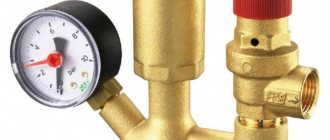
One small valve of a simple design can protect you from all these troubles. Based on the fact that pressure increases to a critical limit in the boiler, the safety valve must be installed as close to it as possible, on the supply pipeline. Some manufacturers of boiler equipment complete their products with a so-called safety group, which includes a relief valve, a pressure gauge and an automatic air vent. The group is mounted directly into the water jacket of the unit.
It should be noted that safety valves for heating are not always used in circuits. For example, when the heat source in the house is a gas or electric boiler, then a reset device is not required. The reason is the presence of automatic safety in these types of heat generators and the absence of any inertia. That is, when the set coolant temperature is reached, the gas burner or electrical element is turned off and heating stops almost immediately.
Another thing is a solid fuel boiler or stove with a water circuit; here the installation of a safety valve is mandatory. When the firewood in the firebox has flared up and the water in the network has reached the required temperature, you need to reduce its heating. The access of air to the combustion chamber is closed and the flame dies out, but the red-hot firebox continues to rise in temperature by inertia. If the process proceeds near the limiting values (temperature 90-95 ºС), then vaporization at such moments is inevitable.
As mentioned above, boiling is followed by an increase in pressure, which can be prevented by the safety valve of the heating system. It will automatically open the way out for the formed steam and release it, thereby reducing the pressure to normal. Then the device will close on its own and will be in standby mode again.
Material of manufacture
Most often, the body of the safety element is made of brass. This is due to the fact that this material is characterized by low thermal expansion, reliability, and is not subject to corrosive processes and its price will pleasantly surprise you.
p, blockquote 34,0,0,0,0 —>
The adjustment unit is usually made of heat-resistant plastic.
p, blockquote 35,0,0,0,0 —>
To summarize, it is worth noting that the safety valve is a very important link in protecting the heating system. The role of this detail is very important, so the choice should be approached responsibly, because The safety of your home's heating system is directly dependent on it.
p, blockquote 36,0,0,0,0 —> p, blockquote 37,0,0,0,1 —>
When choosing a valve, you need to pay attention to all technical indicators and quality of the product. It is important to set up and install the safety valve correctly, because... The slightest inaccuracies can lead to the device not responding in a timely manner in the event of an emergency.
Rules for installation and operation of the device
Installation of the product on the pipeline must be done with sealing gaskets without distortions. The working substance passing through the valve must be free of mechanical inclusions and abrasive particles. It is advisable to install a mesh filter of the appropriate diameter at the inlet to the system. Installation of the device with a spring mechanism is carried out strictly in a vertical position, with the lid facing up. For the lever included in the design of the lever-load device, it is necessary to ensure a horizontal position. It is not recommended to place shut-off elements in the form of taps, gate valves, or levers in front of a relief valve.
To eliminate excess liquid, it is necessary to install an additional outlet used to drain water into the sewer pipeline or return pipe.
During operation, it is necessary to periodically inspect the device, since in products with a spring mechanism, displacement of the plate towards the walls of the housing may occur.
Required tools and materials
To install the valve you will need:
- adjustable wrench;
- fum - ribbon or tow;
- special paste for sealing joints.
For example, let's look at the installation diagram of the device in front of the hot water heater in the apartment.
Work progress
Each product designed for releasing excess pressure is equipped with installation instructions, which should be carefully studied before starting work. Before installation, you also need to disconnect the water heater from the network and drain the water from it. The valve must be placed on the cold water supply up to the shut-off valve. The valve installation sequence is as follows:
- marking the installation site;
- removing a part of the pipe of a size corresponding to the length of the device body;
- threading the ends of pipes:
- covering the threaded part with tow or fum tape;
- screwing the valve onto the pipe thread;
- connecting to another pipe a pipe leading to the sewer system.
- tightening the threaded connection using an adjustable wrench;
- sealing the joint with a special paste;
- setting up the device in accordance with the passport values (if necessary).
Connection type
Based on the type of connection or connection to the pipeline, valves are divided into:
- flanged products - equipped with flange plates at each outlet and connected to mating flanges at the ends of the pipes using bolts;
- threaded - imply the presence of outlet pipes with external threads;
- welded - attached to the gas pipeline by welding and ensure 100% tightness.
Safety valve functions
After water is poured into the heating system, under the influence of temperature it heats up and increases in volume. This, in turn, increases the pressure in the pipes and water circuit of the boiler. All equipment connected to the boiler suffers from this.
An increase in pressure of more than 3.6 bar contributes to:
- water leakage at pipe fastening points;
- connecting elements and pipe fasteners can also fail and stop holding on;
- boiler explosion;
- shorted wiring in the boiler room.
The most dangerous is a solid fuel boiler.
where it is not possible to regulate temperature and pressure. The most dangerous in this regard are considered to be solid fuel boilers, in which there is no possibility to regulate the temperature of the water in the system. Equipment running on gas or electricity is much easier to adjust. You can set any temperature, and the automation will keep it.
As a rule, safety sensors are installed in the system, which regulate the temperature and turn off the heating elements in critical situations.
You will see how to properly set the safety valve in this video:
If the temperature of the heating liquid rises to 95°C, too much steam begins to be released. As a result, the pressure will rise. It is to solve this situation that a safety valve is installed. If there is excess pressure, the sensor opens and releases excess steam. After the situation normalizes, it automatically closes and the system continues to operate as normal.
Its installation is necessary not only in solid fuel boilers, but also in steam ones. Can also be installed in ovens that have a water circuit. This valve is installed by default in most factory-installed space heating equipment. The device can be installed directly in the boiler or nearby in the system pipe. This is of no fundamental importance, since steam will come out from anywhere in the system.
Types of overpressure relief valves
There are several generally accepted classifications of safety valves. Depending on the method of action, there are:
- direct-acting valves - devices are activated by direct action of the working medium on the spring mechanism;
- indirect action - operate under the influence of an external pressure source (hydraulic fluid or electric drive).
Based on the type of load on the membrane, the device is divided into the following types:
- cargo - the most common mechanism for adjusting the working pressure in the system;
- spring - the pressure of the working medium is counteracted by a lever that presses on the rod, holding it in the closed position;
- lever-spring – hybrid devices equipped with a spring and a lever mechanism;
- magnetic spring valves are indirectly acting valves equipped with an electromagnetic drive.
Modern manufacturers offer other types of excess pressure relief valves.
For example, there are thermal relief valves on the market that respond not to an increase in pressure, but to an increase in the temperature of the working environment. They may have a remote or built-in temperature sensor, which operates on the basis of a heat-sensitive liquid located in a bellows.
When the water temperature heats up to 95-100 degrees, the liquid in the capillary tube of the sensor flask puts pressure on the bellows, which opens the rod and drains the superheated water to normalize the pressure.
According to the control method, the valves are divided into two groups: manual and automatic - they are controlled, respectively, manually or are activated automatically when the pressure of the working medium increases. In addition, there are regulated and unregulated. Adjustment allows you to set any water pressure threshold.
Depending on the type of working medium, there are water and air. The former remove excess liquid, the latter discharge excess gases from the system, preventing airing of circuits in closed heating systems.
There are also control valves equipped with a built-in thermostat, which changes the throughput of the device, slightly opening or completely blocking the outflow of the working medium. Such devices are usually installed at the entrance to the heating radiator in the room.
Device
The standard design of an overpressure relief valve includes:
- cast body made of stainless steel, brass or bronze;
- plate - the main shut-off element that blocks the flow of the medium;
- plate lever - used to control this part;
- safety lever - performs protective functions if the main locking element does not work;
- tuning knob;
- springs;
- additional details (control buttons, counters, dials, barometer, etc.).
Burst valve for boiler. Calculation
The calculation of the safety device must be carried out in accordance with the methodology presented in SNiP II-35 “Boiler installations”.
Since manufacturers rarely indicate the actual height of the rod lift in the technical specifications, in the calculation this parameter is equal to 1/20 of the seat diameter. For this reason, the valve size as a result of this calculation is somewhat overestimated. In any case, after selecting a device, it is necessary to compare the thermal power of the heating system with the maximum power recommended in the technical description for the selected standard size.
Installation of a safety valve is required to protect the heating system from exceeding the pressure level above the maximum permissible value. For this reason, the calculation of this device should be reduced to calculating the maximum permissible increase in coolant volume and identifying possible sources of excess pressure.
Sources of volume growth can be:
- Overheating in a heat exchange or boiler unit with subsequent vaporization. When vaporizing, a liquid can increase its volume by 461 times, so this factor is the predominant factor when choosing a valve.
- Failure of automatic control of make-up lines of boiler houses and independent heating systems. This may also be a predominant factor in valve selection.
- The coolant, heating up in a heat exchange or boiler unit, increases in volume. When heated, the specific volume increase is from 0 to 100 °C, which is only 4%, so when selecting the size of a device of this type, this is not a fundamental point.
The selected equipment must ensure the discharge of the calculated amount of coolant, according to the most significant factor in the increase in volume.
Tips for choosing the optimal model
Before choosing a specific safety equipment, you must familiarize yourself in detail with the technical characteristics of the boiler installation.
The operation of the safety valve is negatively affected by sub-zero temperatures. Therefore, a fairly important characteristic for the device is the presence of frost protection
Do not neglect to study the manufacturer’s instructions, which indicate all the limit values.
Several criteria play a decisive role in choosing a heating device:
- Boiler performance.
- The maximum permissible medium pressure for the thermal power of heating equipment.
- Safety valve diameter.
You should check that the pressure regulator in the device has a range that includes the parameters of a particular boiler. The response pressure should be 25-30% greater than the operating pressure required for stable operation of the system.
The higher the operating pressure, the less time the device should spend on operation. The gap between the pressure at the start of movement and when the shutter is fully opened should be 15% for a nominal value less than 2.5 atm, 10% for higher parameters
The diameter of the safety valve cannot be less than the connector of the inlet pipe. Otherwise, constant hydraulic resistance will not allow the fuse to fully perform its immediate tasks.
The optimal material for manufacturing equipment is brass. It has a low coefficient of thermal expansion, which prevents destruction of the housing from exposure to strong pressure.
The control unit is made from heat-resistant plastic materials that maintain the required rigidity even when in contact with boiling liquid.
Operating principle
Most ordinary users faced with closed water heating systems are familiar with only one type of safety valve - a simple spring valve with a fixed setting, shown in the photo. The reason is clear - these products are universally installed on any boilers, since they are part of the safety group along with a pressure gauge and an air vent.
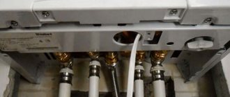
Note. Wall-mounted heat generators operating on electricity and natural gas are equipped with safety elements from the factory. They are placed inside the case and are not visible from the outside.
Let's understand how a regular emergency valve works, shown in the diagram above:
- Under normal conditions, the diaphragm, attached to the stem and supported by a spring, sits tightly in the seat and seals the passage.
- If the coolant overheats, it expands and creates excess pressure in a closed system, partially compensated by the expansion tank.
- When the amount of water pressure reaches the valve response threshold (usually 3 Bar), the spring is compressed under its influence and the membrane opens the passage. The boiling coolant is automatically discharged until the spring has enough strength to close the flow area again.
- In the event of an emergency, the owner of the house can relieve excess pressure himself by turning the handle at the top of the product.
A few words about where the relief valve is installed along with the safety group in a closed heating system. Its place is on the supply line in the immediate vicinity of the boiler (recommended no further than 0.5 m).
Important point. It is prohibited to install taps, valves and other shut-off devices on the pipeline leading from the heat generator to the safety elements.
You should not tightly connect the pipe of the product to the sewer - wet spots or puddles will indicate the valve has been activated and problems in the heating network. For example, the expansion tank failed or the circulation pump malfunctioned when working with a solid fuel boiler (the electricity may have been turned off). Often the device begins to leak due to debris getting between the seat and the plate. More about his work is described in the video:
Additional information. Masters and installers call spring relief valves blasting valves because the pressure of the coolant compresses the spring and causes the membrane to explode. Do not confuse them with explosive elements installed on the chimneys of industrial boiler houses that burn natural gas.
