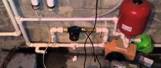
As heat sources for heating a house, solid fuel boilers have their own design features and must be included in the heating system in a certain way. The goal is the correct and durable operation of the installation and its protection in various emergency situations. One of the main elements involved in the piping scheme is a three-way valve for a solid fuel boiler.
Three way valve for boiler
Using the Safety Valve
This is not the same thing as a safety valve. The latter simply relieves pressure in the system, but does not cool it. Another thing is the boiler overheating protection valve, which takes hot water from the system and instead supplies cold water from the water supply. The device is non-volatile and is connected to the supply and return lines, water supply network and sewerage system.
When the coolant temperature is above 105 ºС, the valve opens and, thanks to a pressure in the water supply of 2-5 Bar, hot water is forced out of the heat generator jacket and pipelines with cold water, after which it goes into the sewer. How the solid fuel boiler protection valve is connected is shown in the diagram:
The disadvantage of this method of protection is that it is not suitable for systems filled with antifreeze liquid. In addition, the scheme is not applicable in conditions where there is no centralized water supply, because along with a power outage, the supply of water from a well or pool will also stop.
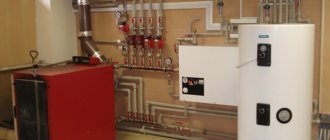
Why use a three way valve
The possibility of convenient and universal operation of boilers is based on the fact that they can easily be connected directly to the heating system.
The only nuance will be the correctness of the action performed, as well as ensuring the required level of protection in the event of various force majeure circumstances. To ensure this system, or rather its functioning under any conditions and situations, a three-way valve for a solid fuel boiler is used. It is used in piping schemes and must be purchased (used) without fail, regardless of the model, power or manufacturer of the boiler itself.
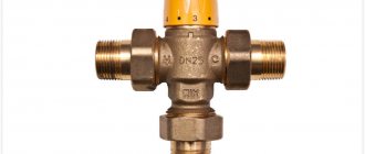
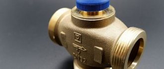
Part appearance
If this element is missing from the system, this can lead to dire consequences - serious damage to the boiler, a decrease in its performance, or even a dangerous situation may arise that threatens the life and health of people in heated rooms and directly next to the boiler itself.
Why is condensation dangerous for a boiler?
When lighting a solid fuel boiler, you have to deal with the fact that the cold coolant washes the walls of the already heated combustion chamber, cools them, which leads to condensation of water vapor, which is invariably present in the flue gases. Water particles, interacting with flue gases, form acids, which leads to the destruction of the inner surface of the combustion chamber and chimney.
But the negative effect of condensate is not limited to this: soot particles that settle on the walls dissolve in drops of water. Under the influence of high temperatures, this mixture sinteres, forming a dense and durable crust on the inner surface of the combustion chamber, the presence of which sharply reduces the intensity of heat exchange between the flue gases and the coolant. The boiler efficiency drops.
Removing the crust is not easy, especially if the boiler’s combustion chamber has a complex heat exchange surface.
It is impossible to completely eliminate the process of condensation formation in a solid fuel boiler, but the duration of this process can be significantly reduced.
Design
A typical safety valve for a boiler has a collapsible design and consists of the following main elements:
Frame. Usually made of brass and shaped like a tee. On its sides there is a lower inlet threaded hole, a side outlet pipe and an upper seat on which the shaped seal is seated.
Locking group. It is a spring-loaded pulley with a cylindrical (disc) end locking element, onto which an elastic rubber seal in the form of a cup (disc) is placed.
Lid. A black cap made of heat-resistant polymer is screwed into the upper threaded pipe of the brass body, holding the spring-loaded rod in the working position. On the upper edges of the lid there are protrusions along which the upper cap, shaped at the bottom, slides, connected to the locking rod. When turned to a certain angle, the cap rises along with the rod and opens the side pipe - this allows you to use the safety valve for heating always open in manual mode.
Cap. The polymer part is usually red in color with a ribbed side surface, and is screwed to the hollow inside of the rod with a screw. The gentle protrusions at the bottom of the cap, when rotated, fall on the teeth of the lid - the handle rises along with the spring-loaded shutter and opens the side channel, allowing you to relieve pressure manually.
Adjusting washer. The inner wall of the cover has a thread in which the adjustment nut rotates; when lowered down, it compresses the spring - thus increasing the valve response threshold. When the nut is unscrewed upward, the spring weakens and the actuation pressure decreases. For turning, the nut is equipped with a transverse slot in the upper part for a flat-head screwdriver.
Valve for water heating boilers - design and appearance
Operating principle and types of valve actuators
The product is produced in different configurations and with different drives, but the principle of operation of the three-way valve remains unchanged: mix two flows with different temperatures into one, the temperature of which is specified by the user or required by the scheme. The liquid inside the valve flows from one pipe to another until its temperature changes and reaches the set value. Then the drive gradually opens the flow from the third pipe, keeping the temperature of the leaving water within the set value. On this basis, such a valve is called a three-way valve.
Operating principle of three-way valve
Any three-way mixing valve has two inlets and one outlet. Flow distribution is carried out using a drive, which comes in several types:
- The thermostatic drive (thermostat) is one of the most popular; it works due to the thermal expansion of the sensing element, as a result of which pressure is placed on the valve stem and the liquid begins to mix.
- A widely used type of drive that is installed in a three-way changeover valve is electric, operating from a signal from the control unit.
- The valve can be controlled by pressing the stem using a thermostatic head drive. It reacts to the air temperature, which it determines itself or using a remote sensor and a capillary tube. The drive is most often used in underfloor heating systems.
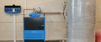
Stationary solid fuel boilers cannot be directly included in the heating system. One of the reasons is to prevent cold water from entering the boiler jacket until it has warmed up. Otherwise, condensation is released on the walls of the firebox, which, mixing with ash, forms a durable layer of soot. It interferes with free heat exchange, reducing the efficiency of the installation, and it is very difficult to clean off carbon deposits. The second reason is that cast iron fireboxes need to be protected from temperature changes in the event of an unexpected pump stop due to a power outage, and then its restart. The task is to prevent cold water from entering the hot boiler, which is why a three-way valve is needed. He will force the coolant to circulate in a small circle until it warms up, and only then will he begin to mix in cold water.
Criterias of choice
Three-way valve for solid fuel boiler
Before choosing a three-way valve for the boiler, you need to find out the operating parameters of the coolant, its flow rate and piping diagram. The temperature and flow rate of the coolant are determined from the design documentation; if it is missing, then the recommended water temperature in the return pipeline can be found in the passport for the solid fuel boiler. As a rule, it is 45-50 ⁰С. The coolant flow rate needs to be known in order to select a three-way valve based on its capacity. If there is no data, you just need to use the formula:
G = 3600Q / s (∆t), where:
- G – water consumption by mass, kg/h;
- Q – thermal power of the heating system;
- с – specific heat capacity of water, equal to 4.187 kJ / (kg ⁰С);
- ∆t – temperature difference in the supply and return pipelines.
Considering that for water the values of mass and volume are identical, the flow rate can be expressed both in kg/h and in dm3/h. Having calculated the flow rate, compare its value with the capacity of the crane indicated in the passport.
It is necessary to select a product by drive type depending on the wiring diagram of the solid fuel installation. The simplest connection diagram uses a three-way thermostatic valve for the boiler:
Here we show the connection of a heating installation with a heat accumulator, the water in which begins to warm up only after the solid fuel boiler has heated the water circulating in a small circle (through pipes No. 3 and 1) to the set temperature. When the coolant heats up, the three-way valve, set to one of three possible temperatures, will begin to open the flow of cold water from pipe No. 2. Then hot water will flow into the heat accumulator tank, replacing the outgoing cold water.
A more complex piping scheme involves the use of a solid fuel boiler with a three-way valve controlled by an external controller:
Diagram of using a solid fuel boiler with a three-way valve
Mixing taps with two types of drives are used here, operating in two coolant circulation circuits. The first one, standing near the heat source, is thermostatic and works according to the principle discussed above. The second has an electric drive, controlled by a controller depending on sensor signals. Here, the operation of the three-way valve is aimed at maintaining the required temperature of the coolant in the heating system circuit. An electrically driven device can also be used in the primary circuit if two or more different boiler units are operating in the boiler room under the control of one controller.
Another criterion by which you should choose a three-way valve for solid fuel boilers is the range of set temperatures. Here we are talking about products with a thermostatic drive, which can be used both in boiler piping and in underfloor heating or hot water systems. Manufacturers offer taps with different adjustment ranges depending on the purpose of the product, for example, from 20 to 43 ⁰С, from 35 to 60 ⁰С and so on. You need to pay attention to this when purchasing; in this example, for connecting to a solid fuel boiler, the second option is preferable.
Before installing the trim, it will be useful to know how to check the three-way valve that you recently purchased. It is not difficult to test a new product: you just need to set the minimum temperature from the adjustable range and pour hot water into pipe No. 3 (see Figure). After some time, a functional tap will turn it off. You can check the valve in an already installed system by measuring the temperature of the water in the return pipeline at the inlet to the solid fuel boiler. Its value must correspond to that set on the thermostat.
How to choose correctly
Before you start directly purchasing a valve, you should find out a lot of points regarding the boiler you are using and the features of the heating system, this will improve the efficiency of the system, otherwise it may lead to a deterioration in the standard performance.
The main thing in this matter is to determine the operating parameters of the coolant (this is easy to find out using the available documentation). In addition, it is necessary to take into account the heating costs and the wiring diagram itself.
The coolant flow and temperature can be determined using design documentation. If there is none, you can use the recommendations that are indicated in the passport of the boiler itself, which is used in the system.
All these parameters are needed in order to select the right valve (you have to choose purely based on throughput).
The drive control system is selected according to the type of heating system and the wiring of the boiler itself. The simplest models and options involve the use of a conventional thermostatic valve (although there are exceptions). And, as already mentioned, to ensure high-quality operation of floor heating, you should use a product with a thermostatic head.
If you plan to work with a complex piping system, then manufacturers recommend using a valve with an external control controller.
Be that as it may, any modern heating system must use a three-way valve, which is an important component in the entire system and there is simply nothing to replace it with - no alternative has been invented.
An exception is the previously used elevator systems, which have not been in use for a long time and are considered obsolete (due to their low efficiency and convenience).
Be sure to take into account that there is not only a mixing valve, but also a separating valve. The first option discussed above implies the possibility of mixing two flows into one, and the second option, a dividing valve, offers the opportunity to divide one flow into two, while regulating the flow to each of the outputs.
Both of these types of valves can be used in the system. However, mixing is necessary in any case, and separation is rarely used in simple heating systems.
The correct choice of valve can be called if the user selects a purchase not only by throughput, but also by temperature. If the first selection criterion is the main one - without taking it into account, one cannot count on the functionality of the system as a whole, then the second criterion implies the duration of operation of the valve - if it is not designed to operate in a system where the temperature is higher than permissible at the valve itself, the part will wear out faster and will require replacement, or will not function at all.
An autonomous heating system is a much more complex mechanism, consisting of a large number of interconnected components and assemblies that perform the corresponding functions. The three-way valve for the boiler in this mechanism plays the role of a mixer in which the temperature of the coolant is adjusted.
This is done so that the pipes are heated evenly and the heating level in each room is approximately the same. If you do not use the part, it will turn out that the water passing through the heat exchanger will not heat up equally, and as a result, some rooms will receive less thermal energy than all other rooms.
Design differences of the device
Based on their design differences, three-way valves are divided into the following types:
- Mixing valve with up and down adjustable stem (“stem-seat”). The rod moves using an electromechanical drive. In fact, here we are talking about extreme automation of the work and adjustment of the system. The mixing valve is designed to connect water flows and thermoregulation. For incoming streams that have different temperatures, two inputs and one output are provided. These valves are often used when installing underfloor heating to prevent the system from overheating.
- The second type is a separating valve that operates on a ball-socket system. The location of the ball changes due to its rotation. This valve is used if the coolant needs to be supplied in several directions at once. In essence, it is a mixer that forms a water flow at the required temperature. The device has good wear resistance, as it is designed to withstand sudden changes in fluid temperatures. It is classified as a shut-off valve. In households where water is consumed in a small volume, it can also be used as a regular mixer.
The shape of the valve is similar to a regular tee. However, its functionality is completely different. The three-way valve is also used as a mixer, as well as an air or hot water distributor.
Reasons that may result in overheating of a solid fuel boiler
Even at the selection and purchase stage, it is important to take into account the performance characteristics of the heating device. Many models that are on sale today have a built-in overheating protection system.
Whether it works or not is the second question. However, it is necessary to adhere to certain knowledge and skills in order to create an effective and safe autonomous heating system at home.
The reliable operation of the heating unit depends on the operating conditions. In case of obvious violations of the technological parameters of heating equipment and abuse of standard safety rules, there is a high probability of an emergency situation.
Possible negative consequences can be prevented even at the stage of installation of a solid fuel boiler. Proper wiring of the heating apparatus will be the key to your safety and reliable operation of the unit in the future.
If we talk in detail, then in each case the protection system of a solid fuel boiler has its own specifics and features. Each heating system has its pros and cons. Eg:
When it comes to solid fuel boilers with natural coolant circulation, it is necessary to take care of the safety and performance of the heating equipment even during installation. The pipes in the system are metal. Moreover, the diameter of such pipes must exceed the diameter of the pipes used to lay the circuit with forced circulation of the coolant. Sensors installed on the water circuit will indicate possible overheating of the coolant. The safety valve and expansion tank play the role of a compensator, reducing excess pressure in the system.
A significant disadvantage of a gravity heating system is the lack of an effective mechanism for adjusting the operating modes of solid fuel boilers.
Great technological opportunities for consumers are provided by working with forced circulation of coolant in the system. Just the presence of a second circuit significantly increases the ability to regulate the heating temperature of the boiler water. The only drawback in the operation of such a system is the running pump, which can cause difficulties during the operation of the heating system.
This is due to the fact that when the power is turned off, the pump stops performing its functions. Stopping the circulation process and inertia of solid fuel heating boilers can lead to overheating of the heating unit. If the boiler equipment is not equipped, a power outage situation is fraught with extremely unpleasant consequences.
Effective protection against overheating of a working solid fuel boiler should be based on the mechanism for removing excess heat generated by the heating device.
The main task that the safety valve solves
The device is a self-contained device, completely independent of external power sources. If most automatic control devices are powered from the mains, then in this case an inconspicuous device plays the role of the last protective barrier for solid fuel boilers from overheating. The simplest device is designed to respond to changes in the temperature of the boiler water circulating through the heating circuit. If the temperature of the coolant has reached a critical level (95 degrees or more), a safety valve is activated, allowing access to cold water into the overheated circuit.
Note: In this case we are talking about a method of protecting the boiler from overheating by adding cold water.
The device you have high hopes for must meet the following requirements:
- high throughput;
- high sensitivity of the thermostatic element located inside the structure;
- compliance with control measurements declared by the manufacturer.
We have already said that the main function assigned to this device is to protect heating equipment from overheating. This is where the basic operating principle of the mechanism follows. By mixing cold and hot water in the heating circuit, the overall temperature of not only the coolant in the system, but also in the heating device is reduced. Consequently, the mechanism is installed on the main pipeline, creating three different directions of movement of the boiler water.
What are the ways to protect heating equipment from overheating?
In order to increase the consumer attractiveness of their products, manufacturing companies try to include any guarantees of their safety in the technical passport of boiler equipment. The uninitiated consumer has no idea about the means of protecting a heating boiler from boiling.
The following methods currently exist to ensure the protection of solid fuel units used for autonomous heating systems. The effectiveness of each method is explained by the operating conditions of boiler equipment and the design features of the units.
In most cases, in the technical data sheet for a heating device, manufacturers recommend using tap water for cooling. In some cases, solid fuel heating boilers are equipped with built-in additional heat exchangers. There are models of boilers with remote heat exchangers. A safety valve is used to prevent overheating. The safety valve is designed only to relieve excessive pressure in the system, while the safety valve allows access to tap water when the boiler overheats.
Exceeding the temperature of the coolant above 100 0C creates excess pressure that opens the valve. Under the influence of tap water, which is supplied under pressure of 2-5 bar, hot water is forced out of the circuit by cold.
The first aspect that causes controversy about cooling with tap water is the lack of electricity to operate the pump. The expansion tank does not contain enough water to cool the boiler.
The second aspect that this cooling method rejects is related to the use of antifreeze as a coolant. If an emergency occurs, up to 150 liters of antifreeze will go into the sewer along with the incoming cold water. Is this method of protection worth it?
The presence of a UPS will allow you to maintain the operation of the circulating pump in a critical situation, with the help of which the coolant will evenly disperse through the pipeline without having time to overheat. As long as the battery capacity lasts, the uninterruptible power supply guarantees the operation of the pump. During this time, the boiler should not have time to heat up to critical parameters; the automation will work, running water through a spare, emergency circuit.
Another way to get out of a critical situation would be to install an emergency circuit in the piping of a solid fuel unit. Switching off the pump can be duplicated by the operation of a spare circuit with natural coolant circulation. The role of the emergency circuit is not to provide heating for residential premises, but only to be able to remove excess thermal energy in an emergency.
This scheme for organizing the protection of the heating unit from overheating is reliable, simple and easy to use. You will not need any special funds for its equipment and installation. The only conditions for such protection to work are:
- the presence of an expansion tank or storage tank in the system;
- use of a petal type check valve only;
- the secondary circuit pipes must be larger in diameter than the conventional heating circuit.
Options for working connection schemes
Heating systems are very diverse and the presence of a check valve is not necessary in all of them. Let's consider several cases when its installation is necessary. First of all, a check valve must be installed on each of the individual circuits in a closed circuit, provided that they are equipped with circulation pumps.
Some craftsmen strongly recommend installing a spring-type check valve in front of the inlet pipe of the only circulation pump in a single-circuit system. They motivate their advice by the fact that in this way pumping equipment can be protected from water hammer.
This is in no way true. Firstly, installing a check valve in a single-circuit system is hardly justified. Secondly, it is always installed after the circulation pump, otherwise using the device loses all meaning.
If two or more boilers are included in the heating circuit, the occurrence of parasitic flows is inevitable. Therefore, connecting a check valve is mandatory
For multi-circuit systems, the presence of a reverse-acting shut-off device is vital. For example, when two boilers are used for heating, electric and solid fuel, or any others.
When one of the circulation pumps is turned off, the pressure in the pipeline will inevitably change and a so-called parasitic flow will appear, which will move in a small circle, which can lead to trouble. It is impossible to do without shut-off valves here.
A similar situation arises when using an indirect heating boiler. Especially if the equipment has a separate pump, if there is no buffer tank, hydraulic arrow or distribution comb.
Here, too, there is a high probability of a parasitic flow, to cut off which a check valve is needed, which is used specifically for arranging a branch with a boiler.
It is mandatory to use shut-off valves in systems with bypass. Such schemes are usually used when converting a scheme from gravitational fluid circulation to forced circulation.
In this case, the valve is placed on the bypass parallel to the circulation pumping equipment. It is assumed that the main mode of operation will be forced. But if the pump is turned off due to lack of electricity or breakdown, the system will automatically switch to natural circulation.
When installing bypass units for heating circuits, the use of check valves is considered mandatory. The figure shows one of the possible bypass connection options
This will happen as follows: the pump stops supplying coolant, the check valve actuator unit ceases to experience pressure and closes.
Then the convection movement of the liquid along the main line resumes. This process will continue until the pump starts working. In addition, experts suggest installing a check valve on the make-up pipeline. This is not necessary, but highly desirable, since it allows you to avoid emptying the heating system for a variety of reasons.
For example, the owner opened a tap on the make-up pipeline to increase the pressure in the system. If, by an unpleasant coincidence, the water supply is cut off at this moment, the coolant will simply squeeze out the remaining cold water and go into the pipeline. As a result, the heating system will be left without liquid, the pressure in it will drop sharply and the boiler will stop.
In the circuits described above, it is important to use the correct valves. To cut off parasitic flows between adjacent circuits, it is advisable to install disk or petal devices. In this case, the hydraulic resistance will be less in the latter option, which must be taken into account when choosing
In this case, the hydraulic resistance will be lower in the latter option, which must be taken into account when choosing.
In heating systems with natural coolant circulation, the use of spring check valves is impractical. Only paddle rotators can be installed here
To install a bypass unit, it is preferable to choose a ball valve. This is due to the fact that it provides almost zero resistance. A disc-type valve can be installed on the make-up pipeline. This should be a model designed for fairly high operating pressure.
Therefore, a check valve may not be installed in all heating systems. It is necessarily used when installing bypasses of all types for boilers and radiators, as well as at pipeline branch points.
How to install
When installing safety drain fittings, observe the following rules:
- Typically, a pressure relief valve in a heating system is installed in a household circuit in a single copy. Its main placement points are directly above the electric, solid fuel, gas boiler on its outlet pipe or nearby in a horizontal pipeline. If this is not possible for technical reasons, the main condition for correct installation is installation in the supply line up to the first shut-off valve.
- The side outlet pipe is usually connected to a sewer or drainage system; if this is technically difficult or the volume of coolant in the circuit is low, you can use a flexible line, which is lowered into a container of suitable volume.
- The liquid must be drained with a stream breaking through a funnel or hydraulic valve to ensure the system is operational when the sewer is clogged.
- When installing in a pipeline, use a tee with a bottom outlet of a suitable diameter, its standard value is 1/2, 3/4, 1 and 2 inches. The diameter of the pipeline supplying the valve should not be less than that of the system.
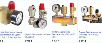
Safety valve groups - types and price
Two final recommendations
Since we have presented a simplified method for calculating and selecting a 3-way valve based on capacity, we strongly advise you to consult knowledgeable people on this matter. If this is not possible, purchase a valve with a reserve, regardless of the price. There is another option: agree with the seller about a possible replacement of the product in case it does not fit.
If you need to install water heating in a large cottage, heated by a radiator network and heated floors, and you plan to provide hot water from an indirect heating boiler, then you will not be able to do it without the help of experienced specialists. You will have to make from 4 to 10 adjustable branches, for each of which you need to calculate and select a three-way valve, and then balance their work as a whole.
Types of valves
So, you can read more about the two existing types of valves below:
- 1. The three way thermostatic boiler valve is an automatic model. It will maintain the set temperature level without additional human intervention. At the same time, the most functional models are equipped with an additional safety system that blocks the movement of coolant if there is no circulation through one of the incoming pipes. This way, the batteries will not boil over.
- 2. The three-way thermal mixing valve for the boiler can be equipped with both automatic and manual control. The fundamental difference will be the need to regularly check the condition of the system so that it does not overheat. Today, mechanical devices have almost been abandoned, as they have been replaced by more advanced units.
Three-way valve for heating with thermostat: principle of operation and purpose
Thermostats are installed on radiator passage plugs. If necessary, these devices completely or partially block the coolant flow. The same function is performed by a faucet, however, if you have a thermostat, you set the necessary parameters once, after which the thermal valve maintains the set temperature on its own. Electronic thermal valves provide the greatest accuracy and functionality.
It is important to understand that the thermostat is not capable of changing the initial power of the heat source, but it allows you to wisely manage thermal energy and create comfortable conditions in the room
The principle of operation of the thermostat
The temperature regulator is a two-way device consisting of two main parts:
- valve ("valve");
- thermal head.
Thermostat device:
| Element | Function | Device | Operating principle |
| Valve | Locking mechanism | Consists of a seat, cone and stem. | The operating rod retracts, reducing the distance between the seat and the cone and thereby reducing the flow. As the distance between these parts increases, the flow, on the contrary, increases. |
| Thermal head | Rod control | A heat-sensitive substance is enclosed in a “bellows” (special cylinder). | The operating principle is based on the expansion of gas and liquids when heated. Under the influence of hot coolant, the substance in the bellows expands, pushing the spring-loaded piston. It acts on the rod with a cone in the direction of the seat. When the coolant flow decreases, cooling occurs and, accordingly, the volume of the active substance decreases. The spring returns the piston, cone and rod to their place, and the flow increases. Repeating the cycle allows you to regulate the degree of heating of the radiator with high precision. |
Varieties
Existing types of valves are capable of working with boiler equipment from leading foreign (Vaillant, Baxi, Ariston, Navien, Viessmann) and domestic (Nevalux) manufacturers using gas, liquid and solid fuels in situations where automatic control of the system operation due to the type of fuel is difficult or broken when the automation fails. Depending on their design and operating principle, safety valves are divided into the following groups:
- According to the purpose of the equipment in which they are installed:
- For heating boilers that have the above design, they are often supplied on fittings in the form of a tee, into which a pressure gauge is additionally installed to check the pressure and a venting valve.
- For hot water boilers, the design includes a flag for draining water.
- Tanks and pressure vessels.
- Pressure pipelines.
- According to the operating principle of the clamping mechanism:
- From a spring, the clamping force of which is regulated by an external or internal nut (its operation is discussed above).
- Lever-load type, used in industrial heating systems designed to discharge large volumes of water; their response threshold can be adjusted by hanging weights. They are suspended on a handle connected to the shut-off valve using a lever principle.
Lever-load modification device
- Locking mechanism speeds:
- Proportional (low-lift spring) - the sealed lock rises in proportion to the pressure and is linearly related to its increase, while the drain hole gradually opens and closes in the same way with a decrease in the volume of coolant. The advantage of the design is the absence of water hammer under various modes of movement of the shut-off valve.
- Two-position (full-lift lever-load) - operate in open-closed positions. When the pressure exceeds the response threshold, the outlet hole opens completely and the excess coolant volume is released. After the pressure in the system is normalized, the outlet is completely blocked; the main drawback of the design is the presence of water hammer.
- By adjustment:
- Non-adjustable (with caps of different colors).
- Adjustable screw parts.
- According to the design of the spring compression adjusting elements:
- An internal washer, the operating principle of which was discussed above.
- External screw, nut, models are used in domestic and communal heating systems with large volumes of coolant.
- Using a handle, a similar adjustment system is used in flanged industrial valves; when the handle is fully raised, it is possible to perform a one-time release of water.
Designs of various models of drain valves
How to build a thermostatic valve
Thermostatic valves come in two types:
- mixing
- flow A entering the valve is distributed into flow B and flow AB - distribution
- flow A entering the valve is distributed into 2 flows
The mixing valve is installed on the return line, and the distribution valve is installed on the supply line. The operation of the valve is controlled by a thermal head with a thermal flask.
The thermoflask is attached using a special sleeve to the surface of the return pipeline in close proximity to the heating boiler. Inside the flask there is a working fluid, the temperature of which is equal to the temperature of the coolant before entering the boiler. If the temperature of the coolant increases, the working fluid increases in volume, and, conversely, when the temperature of the coolant decreases, the volume of the working fluid decreases. Expanding or contracting, the working fluid presses on the rod, closing or opening the thermostatic valve.
Using a thermal head, you can set a certain temperature, above (below) which the coolant will not be heated. How to set the temperature by choosing the operating modes of the thermal head is described in detail in the instructions for it.
Another feature of the thermostatic valve is that it reduces the flow of coolant to the boiler, but never closes it or opens it completely, protecting the boiler from overheating and boiling. The valve is completely closed only when the boiler is started.
Three-way valve device
Any valve has three holes: two incoming and one outlet. Inside there is a special drive that regulates the incoming flows.
Design and principle of operation of a three-way valve
The passages between the three chambers, which are constructed by casting inside a brass body with a triple pipe, are blocked by poppet valves. The latter are arranged on one plane - a rod, which comes out of the body on the fourth side.
A three-way mixing valve for a boiler functions in such a way that when the stem is pressed, a path will open for one flow and evenly close the path for another. At the end of everything, water of the required temperature will be obtained in the mixing chamber of the valve. Through a third pipe, water is removed from the brass body.
Using a thermal head with an external temperature sensor, the degree of pressure on the rod and control are carried out.
In a separating valve, everything happens in the same way, only when you press the rod, the flow branches into two, and in the switching element, the electric drive changes the path of movement.
Adjusting a three-way valve using a thermostatic head with a regulator is a fairly common method, since it is quite accurate and easy and, moreover, does not use electricity.
There is also a four-way mixing valve for heating.
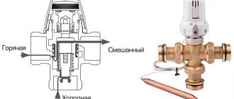
Thermal mixing valve design and operating principle
Like most parts and structural elements of a solid fuel boiler, the three-pass or also has a simple and understandable design. It includes:
- main body;
- spring-loaded rod;
- two dampers, disc type;
- thermostatic element (head with fixed positions).
The diagram shows in detail the mechanism in cross-section, where and how its main elements are located.
Looking at the design of the device, it is not difficult to understand the principle of operation. Let's take a closer look at the processes taking place.
During normal operation of the heating system, the main dampers, located linearly, are in the open position. Insufficiently hot water flows freely from the boiler into the heating circuit.
The thermostatic head, equipped with a temperature-sensitive liquid sensor, is in the standard position. If an emergency situation occurs, for example: coolant begins to flow into the system from the boiler side, the temperature of which exceeds the specified parameters. The temperature control sensor is activated, driving the rod. The operating mechanism closes the main, direct-flow passage, while simultaneously opening a passage from the side through which cold water flows. As a result of mixing water of different temperatures, the temperature equalizes to the established norm. The coolant, already at normal temperature, leaves the device through the pipe into the heating system. The adjustment of the thermostatic head of the device is determined by the degree to which the bellows with the expanding liquid is pressed onto the rod. Accordingly, determines the sensitivity of the device.
The moment the device operates is determined by adjusting the head, set to a certain temperature.
If the water continues to heat up as a result of the actions taken, the device shuts off the main incoming flow, allowing access to cold water from the third pipe. The rod in this case is in the lowest position. Water from the third pipe is already mixed into the main flow. When the temperature of the coolant changes downward, the rod, under the action of the sensor, reduces the pressure, opening access to hot water.
In order to achieve proper operation of the entire mechanism, it is necessary to strictly comply with the requirements for its installation. can be installed in a right-handed or left-handed version, both on the return and on the supply circuit. During operation, the device requires absolutely no maintenance.
Installation Rules
When installing a thermo-mixing valve for a solid fuel boiler, the direction of movement of the heating water in the network is taken into account. It is usually marked with an indicator directly on the product body. It is necessary to indicate that such a valve can be installed in a heating circuit, both vertically and horizontally.
Valve connection diagram for piping
At the same time, when piping the circuit, it is of great importance to comply with the established rules, so that in the future the heat supply system functions properly:
- Mandatory installation of pressure gauges before and after TC.
- A filter is installed in front of the valve to prevent dirt from clogging the working holes.
- The device body must not bear any load.
- For high-quality adjustment, a throttling device is installed in front of it.
- During installation, the housing must be located under the drive.
Additionally, it will be necessary to provide straight sections of pipes before and after the short-running device, according to factory recommendations. Otherwise, the valve will not be able to provide the technical parameters declared by the manufacturer. The product warranty will also be violated.
Why might a valve leak?
The pressure relief valve in the heating system can leak for various reasons. In some situations, this is an acceptable natural process; in other cases, a leak indicates a malfunction of the device.
Leakage of the protection valve can be caused by the following reasons:
- Damage to the sealed rubber cup or disc as a result of repeated use. If during repairs a replacement part cannot be found on sale or is not included in the package, you will have to replace the device completely.
- In spring types, the opening of the side drain pipe occurs gradually; at borderline pressure values or short-term surges, the valve may partially operate and drip, which does not indicate its malfunction.
- Leakage can be caused by incorrect settings or malfunctions of the expansion tank - damage to its membrane, air escaping through a depressurized housing or a damaged nipple. In this case, sharp pressure surges are possible as a result of water hammer, causing periodic short-term leakage of coolant through the safety valve.
- The cause of leakage in some adjustable valves is fluid seeping down the stem through the top during actuation.
- If a back pressure is created at the outlet pipe above the device's response threshold, a leak will also occur.
Appearance, cost of some brands of drain valves
The safety valve of steam boilers is designed to protect them from excess pressure in the system caused by various factors, and is a mandatory element when operating this type of equipment. There is a wide range of safety devices on sale from Chinese, domestic and European manufacturers, which are characterized by a relatively low cost. When purchasing, it is rational to choose a protective group from several devices, which additionally includes a pressure gauge and an air release valve.
What are three-way valves?
Today there are a lot of different options, differing both in configuration and in appearance, but the principle of operation is unchanged. The simplest one is a mixing valve, divided into only 2 types:
- Three-way mixing valve;
- Pre-set valve.
(in the first case, adjustment is carried out in normal mode, in the second, adjustment is possible at the user’s discretion).
It is quite simple to distinguish the valve from other parts offered on the market - the valve always has 3 pipes:
- The first is supplied with a hot stream;
- The second is supplied with a cold stream;
- The third pipe is the outlet and a mixed, temperature-balanced flow passes through it.
Flow direction
The main task of this part is to protect against cold liquid entering the boiler jacket during its initial heating.
If you do not use the valve, or install it incorrectly, hot water will not flow into the system, and accordingly, there can be no talk of any heating.
Due to the valve, the coolant will circulate in the primary circuit until it warms up to the required temperature - depending on the type of boiler, this value can range from 40 to 50 degrees.
After the temperature is reached, the thermostat (which is responsible for checking the current degree in the circuit) interacts with the rod, which, in turn, will open to remove cold water from the existing heating system.
Water is dripping from the safety valve. What to do
Storage water heaters today are in increasing demand among our compatriots. These units simply allow them to effectively solve many business problems, but sometimes it happens that the device itself becomes the source of the problem.
One of the most common problems you encounter is water leakage. If water drips from the safety valve, then it is necessary to establish the cause as soon as possible, because in some cases this process should not be considered a malfunction. That is why there is no need to rush into the decision to call a water heater repair specialist.
Possible causes of malfunction
The reasons for water leakage from the valve may be:
- Valve malfunction;
- Incorrectly set pressure difference in the system;
- Other reasons, in particular, water may leak from the valve, but this will not be considered a failure.
The first two reasons involve repairing the unit.
Troubleshooting Methods
Gas water heaters should be tested first. It is necessary to determine in what situation the water leaks out.
If you notice that water flows out during the heating process, then most likely your unit is fully operational. The fact is that when heated, water expands, and accordingly the pressure of the liquid on the walls of the tank increases
When the pressure exceeds the norm, the valve gets rid of excess water. A solution to this problem can be to connect a rubber hose and lead it into a sewer or container of the required size.
If the safety valve of the water heater allows cold water to pass through, then most likely the reason is that the pressure in the water supply is too high. The solution to this problem is to install a reducer to normalize the pressure in the water supply network. To do this, you must contact a qualified specialist. You also cannot do without the help of a professional if you are inclined to conclude that the cause of the water leak is a malfunction of the valve itself.
Therefore, the first step to solving water heater leakage problems is to determine the cause of the leakage and determine the nature of the problem. Remember that it is always safer to seek help from a professional than to repair complex equipment yourself, because inept repairs can lead to a more complex malfunction.
Nominal diameter and adjustment
The flow area of the safety valve must be equal to or greater than the cross-section of the pipe on which it is installed. Otherwise, the hydraulic resistance of the device will be too large, as a result of which the operation of the system will be disrupted.
The adjustment of the heating system safety valve depends on the type of clamping mechanism. Spring devices have a cap, the rotation of which sets the pre-compression of the spring. These products are characterized by high adjustment accuracy of +/- 0.2 atm.
Lever-weight valves are adjusted with less precision. To do this, you need to move the load along the lever or increase its mass.
Rice. 3. Independent connection diagram of IHP with a pressure maintenance device
This scheme is somewhat more expensive than the dependent one, but at the same time it protects in-house heating devices from low-quality coolant coming from the central network. If it is necessary, in addition to heating, to provide centralized hot water supply, then additionally install one or more heat exchangers. Depending on the ratio of heating and hot water loads, single-stage and two-stage water heater connection schemes are used.
Examples and ROI
In Ukraine, modern automated heating stations with an independent connection scheme are offered by the Austrian company Herz.
IHP from Herz operate at the temperature of network water in the primary circuit (central heating supply) – 110–140°C / 65–80°C. At the same time, the temperature in the indoor heating system is ensured at 90–55°C / 70–45°C. The nominal pressure in the primary circuit is up to 16 bar. Operating pressure in the secondary circuit is from 2 to 10 bar. To maintain pressure in the system, a membrane expansion tank or, in the case of systems with a power of more than 300 kW, a pressure maintenance unit is used. Coolant circulation is carried out by highly efficient frequency-controlled pumps.
The ITP configuration includes circuits based on a two-way valve or a combi-valve - a flow regulator with an electric drive, and a plate or brazed heat exchanger. Weather-dependent regulation of coolant temperature and temperature settings are carried out by the controller. At the same time, it is possible to organize remote access and control of equipment via a GPRS modem. To account for heat consumption, an ultrasonic flow meter with a computer is used.
In addition to IHP, residential heating units are also used for multi-storey buildings. They allow the consumer to individually regulate the operation of the heating and hot water system and provide convenient accounting of energy consumption. For example, the Herz DeLuxe heating unit is designed for a maximum operating temperature of 90°C, a maximum operating pressure of 10 bar and provides a hot water flow of up to 15 l/min. Such heating points are installed directly on each consumer (apartment). There are options for open or hidden installation in the wall, as well as with a mixing unit for low-temperature panel radiant heating, for example: warm walls, warm floors (Fig. 4).
Rice. 4. Compact apartment heating substation Herz Bregenz
The payback time for investments in ITP when modernizing buildings ranges from 1 to 5 years and depends on the equipment used, the size of the building and the type of system. It is worth remembering that the installation of individual heating points is an important and necessary step, but not the only one on the path to energy efficiency in the heating system of a residential building. The greatest effect is achieved in conjunction with balancing the heating system and installing thermostatic valves on heating devices.
Views: 5,337
Simple circuits
Fig. 1 Boiler piping diagram in an open system with natural circulation
The simplest is the wiring diagram for a solid fuel boiler for a single-circuit heating system with natural (gravitational) coolant circulation. As a rule, such systems use metal (most often steel) pipes of relatively large diameter, corresponding to the diameter of the boiler outlet and inlet pipes. It is best if their diameter is the same. This will, along with other factors, reduce hydraulic resistance and create better conditions for natural circulation. Such schemes are characterized by maximum simplicity and in the boiler piping it is necessary to try to avoid unnecessary elements that, to one degree or another, impede the natural movement of the coolant. Therefore, it is necessary to use shut-off or control valves to a minimum and only in places where it is impossible to do without them. Also, the presence of various filters in the circuit of such a system is undesirable. Most often, such systems are open. The expansion tank in them performs the function of creating excess pressure and removing air, therefore it is installed at the highest point, at the maximum possible height (under the ceiling or in the attic).
In Fig. 1 : 1 - boiler; 2 - chimney; 3 - supply pipe (diameter 40-50 mm); 4 — “return” (diameter 40-50 mm); 5 - pipe (1/2); 6 - open type expansion tank.
In systems with combined circulation
Fig. 2 Piping diagram for an open system with combined circulation
The scheme for a system with combined (combined) circulation is more complex, since it already provides for the presence of a special circulation pump, as well as the necessary elements of its piping (bypass, shut-off valves, mechanical filter, air valve). A bypass with a circulation pump can be installed both on the supply pipe and on the return pipe, depending on the availability of space for installation and the convenience of further maintenance.
The air valve is included in the bypass if it is installed on a horizontal section of the pipe and the design of the pump itself does not provide for the possibility of bleeding air.
In the event of a lack of electricity, the tap on the straight bypass pipe opens and the system operates with natural circulation. Instead of a tap, a valve is sometimes installed in this place, which opens automatically in the absence of electricity.
In Fig. 2: 1 - boiler; 2 - chimney; 3 - supply pipe; 4 — “return”; 5 — pipe 1/2″; 6 — expansion tank; 7 - shut-off valves; 8 - circulation pump; 9 - filter; 10, 11 - possible locations of the bypass on the “return” or supply line.
If the heating system is closed, then instead of the usual open expansion tank, a sealed membrane is installed in it. This makes it possible to provide a given excess pressure (usually it is about 1.5 bar (0.15 MPa). In addition, such a circuit must necessarily include a safety unit (safety valve, pressure gauge, air valve).
In this case, it is necessary to remember such features of solid fuel heat generators as great inertia and the difficulty of quickly regulating the combustion temperature of the fuel, and therefore the coolant. Therefore, when piping such a boiler with polypropylene, it must be remembered that the supply pipe coming out of it must be metal at a distance of at least 1.5 m or until the first branch. The “return” can be completely plastic, since the liquid temperature in it rarely exceeds 70-80 ° C. But its internal diameter must correspond to the internal diameter of the metal supply pipe.
The basic principle of protecting the boiler from condensation
To protect a solid fuel boiler from the formation of condensation, it is necessary to eliminate the situation in which this process is possible. To do this, do not allow cold coolant to enter the boiler. The return temperature should be 20 degrees less than the supply temperature. In this case, the supply temperature must be at least 60 C.
The simplest method is to heat a small amount of coolant in the boiler to the nominal temperature, create a small heating circuit for its movement and gradually add the rest of the cold coolant to the hot water.
The idea is simple, but it can be implemented in various ways. For example, some manufacturers offer to purchase a ready-made mixing unit, the cost of which can be 25 000
and more rubles.
For example, the FAR company (Italy) offers similar equipment for 28,500 rubles
, and the
Laddomat
sells a mixing unit for
25,500 rubles
.
A more economical, but no less effective way to protect a solid fuel boiler from condensation is to regulate the temperature of the coolant supplied to the boiler using a thermostatic valve with a thermal head.
Principle of operation
The valve that protects the boiler has a simple device and operates on a principle that is understandable even to a schoolchild. The device consists of a straight fitting with a 90-degree outlet and a spring-loaded seal that closes the side passage. When the pressure in the system increases due to overheating, exceeding the pressing force of the spring holding the valve in a stationary position, it rises up and opens the side hole.
Excess liquid begins to pour out from the side and is sent to a container, drainage or sewer system. After bleeding part of the coolant, the pressure in the system and on the valve weakens, the spring puts it in place, closing the side pipe.
Spring-type structural device
Working principle of the part
There are many types of valves, differing in the type of actuator used, configurations, control methods, etc. There are several models according to the control system, as well as the type of drive.
One of the most common is a valve that uses a thermostatic actuator, in other words, an actuator is installed in the part, controlled by a thermostat. This device works due to the expansion effect of the element (in the case of expansion, the valve stem is pressed, after which liquids with different temperatures are mixed). This type of valve is the most popular.
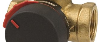
Appearance
The second type, no less common, is the electrical control method. In this case, the valve stem is activated after a signal from the electronic control unit.
The third type is distinguished by a control element - the rod is pressed using a thermostatic head. The reaction occurs depending on the change in air temperature, which is determined by the head itself, or by means of a sensor carried outside using a capillary tube.
Such a drive is most relevant in the case of installation and further operation of floor heating systems.
The valve is also necessary because it prevents the formation of carbon deposits (if cold water flows to the jacket, the condensate that appears on it will mix with ash, thereby creating carbon deposits, which in turn reduces the efficiency of heat transfer, which reduces the efficiency of the boiler itself and system on which it is installed).