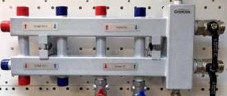
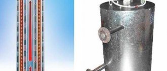
When designing a heating system for a room that you are going to warm up so that it is cozy, warm and dry, you need to decide with what device the water will be evenly distributed throughout all the pipes and radiators. For a small country house or garage this question does not arise. Heating systems there are almost always single-circuit and do not require auxiliary devices. However, if the task is to heat a multi-room cottage, which has two or even three floors, with warm floors and several circuits, then a hydraulic arrow, assembled with your own hands and installed in the heating system, is necessary.
How much will it cost to install a hydraulic arrow with a manifold?
We looked at what a hydraulic arrow in heating is and why it is needed.
Now let’s try to figure out how much it will cost to install such a structure together with a collector and when it is necessary to resort to such a service. The hydraulic separator and manifold themselves are not cheap components. In addition, their installation entails a number of additional costs. Here are the average prices that exist today on the market for these services:
- Hydraulic separator (factory production) – 200 euros;
- Collector (factory) – 300 euros;
- Trims (taps, fittings) – 100 euros;
- Controller (needed to control pumps outside the jurisdiction of the boiler) – 400 euros;
- Installer services (25% of the cost of materials) – 250 euros.
The total is 1250 euros - a pretty decent amount. Therefore, before installing a hydraulic arrow, you need to make sure that it is really necessary. If the installation specialist is not committed, then he will recommend installing a separator only if there are three or more heating circuits (excluding the boiler).
Note. The operation of two pumps, for example in a system of radiators and heated floors, can be coordinated using boiler automation
The boiler always has priority, so when it is turned on, other pumps are turned off.
Of course, you can use a hydraulic gun with a home-made manifold, the manufacturing scheme of which will not differ in any way from the factory version. However, the quality of the material and welds is unlikely to meet technical standards. By saving on materials, you can ultimately significantly reduce the reliability of the system. And it’s good if the breakdown occurs not at the height of the heating season.
Polypropylene hydraulic separator - a simple but unreliable option
What conclusion can be drawn from this article? Firstly, the versatility of the hydraulic gun, which is so often talked about, is too exaggerated. It should be used only in one case - to coordinate the operation of several pumps with different capacities. Secondly, for reliable operation of the system, it is better to use a separator with a factory-made manifold, and entrust the installation to specialists whose goal is not to enrich themselves at the expense of clients, but to actually optimize the operation of autonomous heating.
What capabilities are attributed to the hydraulic separator?
Among heating engineers, there are diametrically opposed opinions regarding the need to install hydraulic switches in heating systems. Adding fuel to the fire are statements from manufacturers of hydraulic equipment, promising increased flexibility in setting operating modes, increased efficiency and heat transfer efficiency. To separate the wheat from the chaff, let's first look at the completely baseless claims about the "outstanding" capabilities of hydraulic separators.
The efficiency of the boiler installation does not depend in any way on the devices installed after the boiler connecting pipes. The beneficial effect of the boiler lies entirely in its conversion ability, that is, in the percentage of heat generated by the generator to the heat absorbed by the coolant. No special piping methods can increase efficiency; it depends only on the surface area of the heat exchanger and the correct choice of coolant circulation rate.
Multi-mode, which is supposedly ensured by installing a hydraulic gun, is also an absolute myth.
The essence of the promises boils down to the fact that if you have a hydraulic switch, you can implement three options for flow ratios in the generator and consumer parts.
The first is absolute equalization of flow, which in practice is only possible if there is no shunting and there is only one circuit in the system. The second option, in which the flow rate in the circuits is greater than through the boiler, supposedly provides increased savings, but in this mode, supercooled coolant inevitably flows through the return to the heat exchanger, which gives rise to a number of negative effects: fogging of the internal surfaces of the combustion chamber or temperature shock.
There are also a number of arguments, each of which represents an incoherent set of terms, but in essence does not reflect anything concrete. These include increasing hydrodynamic stability, increasing the service life of equipment, controlling temperature distribution and others like them.
You can also come across the statement that the hydraulic separator allows you to stabilize the balancing of the hydraulic system, which in practice turns out to be exactly the opposite. If in the absence of a hydraulic switch the system’s reaction to a change in the flow in any part of it is inevitable, then in the presence of a separator it is also completely unpredictable.
Real Application Area
However, the thermal hydraulic separator is far from a useless device. This is a hydraulic device and the principle of its operation is described in sufficient detail in specialized literature. The hydraulic arrow has a well-defined, albeit rather narrow, area of application.
The most important benefit of a hydraulic separator is the ability to coordinate the operation of several circulation pumps in the generator and consumer parts of the system. It often happens that circuits connected to a common collector unit are supplied with pumps whose performance differs by 2 or more times.
In this case, the most powerful pump creates a pressure difference so high that the intake of coolant by other circulation devices is impossible. Several decades ago, this problem was solved by so-called washering - artificially lowering the flow in consumer circuits by welding metal plates with different hole diameters into the pipe.
The hydraulic arrow bypasses the supply and return lines, due to which the vacuum and excess pressure in them are leveled.
The second special case is the excess productivity of the boiler in relation to the consumption of the distribution circuits. This situation is typical for systems in which a number of consumers do not work on a permanent basis. For example, an indirect heating boiler, a swimming pool heat exchanger and heating circuits of buildings that are heated only from time to time can be linked to the general hydraulics.
Installing a hydraulic valve in such systems allows you to maintain the rated power of the boiler and the circulation speed all the time, while the excess heated coolant flows back into the boiler. When an additional consumer is turned on, the difference in costs is reduced and the excess is no longer sent to the heat exchanger, but to an open circuit.
The hydraulic arrow can also serve as a collector for the generator part when coordinating the operation of two boilers, especially if their power differs significantly.
An additional effect from the operation of the water gun can be called protection of the boiler from temperature shock, but for this, the flow rate in the generator part must exceed the flow rate in the consumer network by at least 20%. The latter is achieved by installing pumps of appropriate capacity.
Schemes for self-manufacturing hydraulic arrows
When assembling a hydraulic arrow with your own hands, the main thing is to make the calculations correctly and have the skills to work with a welding machine.
First of all, it is necessary to find the optimal dimensions of the hydraulic separator:
- internal diameter: divide the sum of all heating boiler capacities in kW by the temperature difference between the supply and return, take the square root of the resulting parameter, and then multiply the last value by 49;
- height: multiply the inner diameter by six.
- spacing between pipes: multiply the internal diameter by two.
Based on the obtained parameters, you need to draw up a drawing or use one of the diagrams of the future hydraulic distributor presented by the Plumber Portal resource. After this, you need to prepare a steel tube of round or square cross-section, which corresponds to the calculated indicators, and weld the required number of pipes with threaded connections into it.
Despite the simplicity of the device, the characteristics of the hydraulic gun must still correspond to specific conditions. Also, when assembling it yourself, you need to understand what to start from.
The classic assembly of a typical hydraulic boom is based on the “three diameter rule”. That is, the diameter of the pipes is three times smaller than the diameter of the main cylinder of the separator. The pipes are diametrically opposite, and their height arrangement is also tied to the main diameter.
Classic hydraulic separator diagram:
Some change in the position of the pipes is also used - a kind of “ladder”. This modification is aimed mainly at more efficient removal of gas and insoluble suspended matter. When circulating through the supply pipe, a slight change in the direction of the liquid flow in a zigzag downward manner contributes to the best elimination of gas bubbles.
On the reverse flow, on the contrary, the step is upward, and this simplifies the removal of solid sediment. In addition, this placement promotes optimal mixing of flows. The proportions are chosen to create vertical flow conditions in the range of 0.1 to 0.2 meters per second.
Exceeding this limit is prohibited. The lower the speed of the vertical flow, the more effective the separation of air and sludge will be. The slower the movement, the better the mixing of flows with different temperatures. As a result, a temperature gradient is formed along the height of the device.
Diagram of a hydraulic arrow with a stepped arrangement of pipes:
If the heating system contains circuits with different temperature conditions, then it is worth using a hydraulic distributor that acts as a collector, and different pairs of pipes will have their own temperature pressure. This will significantly reduce the load on thermostatic devices, making the entire system more manageable, efficient and economical.
The closer the pair of pipes is to the middle, the lower the temperature pressure in the supply tube, and the smaller the temperature difference in the supply and return. For example, for batteries the best mode is 75 degrees in supply with a difference Δt = 20 ºС, and for a heated floor system 40÷45 with Δt = 5 ºС is enough.
Diagram of a hydraulic separator with three outputs to the heating circuits:
Horizontal placement. In such variations, of course, there is no question of removing sediment and air. The placement of fittings varies significantly - to effectively move liquid, circuits are often used even in the opposite direction of the flow of the “small” and heating circuits.
Such a hydraulic arrow is made in order, for example, to place equipment more compactly in a boiler room, since the counter direction of flows makes it possible to slightly reduce the diameter of the tubes. However, the design must meet certain requirements:
- between the pipes of one circuit a gap of at least 4d must be maintained;
- if the inlet pipes have a diameter of less than 50 mm, then the distance between them should not be less than 200 mm.
Options for horizontal hydraulic separator circuits:
There are also completely “outlandish” designs. For example, one craftsman was able to build a hydraulic arrow from two sections of an ordinary cast-iron radiator. This device copes with hydraulic separation without problems. However, this method requires very reliable thermal insulation of the device, otherwise it will result in absolutely unproductive heat losses.
Schematic solution for shifting pipes
The classic version of a hydraulic separator involves the creation of pipes symmetrically located relative to one another. However, a circuit version of a slightly different configuration is also practiced, where the pipes are located asymmetrically. What does this give?
Manufacturing diagram of a hydraulic separator in which the secondary circuit pipes are slightly offset relative to the primary circuit pipes. According to the inventors (and proven by practice), this option seems to be more productive in filtering particles and separating air
As the practical application of asymmetrical circuits shows, in this case more efficient air separation occurs, and better filtration (sediment) of suspended particles present in the coolant is achieved.
How to open a mortise lock without a key
First, we’ll talk about how to cope with simple interior door mechanisms.
You may need some things that you almost always have on hand:
- Everyone has a plastic card in their wallet.
- Many women are fond of knitting - a knitting needle will help open the door.
- It is not difficult to find a sheet of paper - free newspapers are distributed on the street.
- A knife, it can easily be replaced by an ordinary metal nail file.
- A thin screwdriver and pliers are found in almost every home.
If you don't have any of these tools, you can always borrow them from your neighbors.
A draft blew through the apartment and the door slammed shut; it was impossible to open it. What to do? This is where a few of our tips may come in handy.
Often the problem turns out to be that the mechanism on the inside of the canvas has turned involuntarily. This becomes an obstacle, but since the tongue itself moves softly and smoothly in the lock, opening the door is not difficult at all. Let's use a knife or a plastic card. We insert a plate into the gap between the canvas and the jamb and push the barrier. When the mechanism moves a little, you can easily open the room.
If you are dealing with a locking device that is locked with a key, the actions are simplified. The door slammed and the key was in it? We think logically and remember how spies operate: we insert the newspaper into a slot on the floor under the lock and push it further, leaving only a “tail” by which it can be pulled back out. Then carefully squeeze the key out of the groove using paper clips, knitting needles or pins. Take your time, be extremely careful, it should land on the paper. When you hear the sound of falling, pull out the newspaper. Voila, now you don’t need any master key!
If the lock slams shut, but there is no key on the other side, you will have to use knitting needles, a file or a pin, but longer, since you need to feel the moving part of the lock. We insert any thin and long object into the keyhole and move it in different directions. When the target is found, press and turn the handle.
More complex locking mechanisms will require a different approach
“Key” locks are quite common. What it is? Pressing the handle button on the inside locks the door. You need to know that strong cotton can cause a problem. As a rule, a high-quality mechanism of this type is equipped with a safety system. In an emergency, inspect the outside of the handle; most likely, you will find a small hole. We select an object that can fit into it: a knitting needle, a hairpin, a nail. We insert and press on the inner part of the mechanism, this will cause the key to open.
A locked latch lock will require more complex steps. Arm yourself with a screwdriver and remove the bolts, then remove the outer part. If the circumstances are such that there are no tools at hand, for these purposes you can use any flat tool at hand - a spoon, a nail file. When the inside of the mechanism is in front of you, carefully examine all the details. You need to find a small bump, press on it and press the handle, combining these two actions and the door will open. At first glance, it may seem difficult to cope with such a lock, but in fact, if everything you need is at hand, you will quickly find your way.
All these methods are good only when the mechanism is simple, but if trouble happens at the entrance to the house, such methods will not work. Next, we will figure out how to open external doors with different locks.
Video description
Video about the hydraulic separator and its purpose:
The calculation is carried out in the following several ways:
- Maximum coolant flow rate.
Calculated by the formula:
D = 3*d*√Mp/Vd
D is the diameter of the hydraulic needle, d is the diameter of the nozzle, MP is the maximum flow for the boiler, Vd is the maximum speed (0.2 m/s).
For example:
7*3*√8/02 = 21*√40 = 21*6.32 = 132.8 cm – 133 cm – diameter of the hydraulic needle.
The diameter of the pipe is 7 cm, the boiler flow rate is 8 cubic meters per hour.
- Highest boiler power.
The calculation is carried out using a similar formula:
D = 3*d*√Mk/(Vd * Traz)
However, some replacement parameters appear in it:
Mk – maximum boiler power, for example 60 kW,
Traz – the difference in heating of the coolant in the supply and return flows, for example 15 degrees.
For example:
21*√60/(02 * 15) = 21*4.4 = 94 cm.
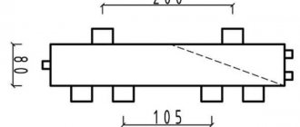
- The length of the body of the hydraulic needle itself. The length of the device depends on the diameter and location of the pipes. Below is a diagram for calculating the characteristics. In the first version it will be equal to 12 diameters, in the second - 13.
Scheme for calculating the length of the hydraulic arrow according to the location of the pipes Source stroychik.ru
Advice! When calculating the parameters of a hydraulic arrow, it is important to determine the maximum possible coolant speed. If the flow moves quickly enough, a characteristic noise will arise in the system, significantly reducing the comfort in the house. Therefore, in order to avoid this negative effect, this parameter is limited to a value not exceeding 0.2 m/s.
Why do you need a hydraulic arrow?
If you plan to install a simple closed-type heating system in your house, where no more than 2 circulation pumps are used, then you definitely do not need a hydraulic separator.
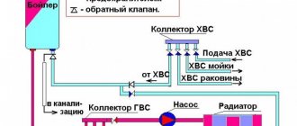
When there are three circuits and pumps, and one of them is designed to work with an indirect heating boiler, then here too you can do without a hydraulic arrow. You need to think about separating heating circuits in a situation where the diagram looks like this:
There is no hydraulic arrow in the presented diagram, but its installation is clearly indispensable. There are 4 circuits in which the same number of pumps of different capacities operate. The most powerful of them will create a vacuum in the supply manifold, and increased pressure in the return manifold. When operating simultaneously, a pump with a lower capacity simply does not have enough strength to overcome this vacuum and it will not be able to take the coolant to its circuit. As a result, the branch will not function because the pumps interfere with each other.
To eliminate the pressure difference ΔP that occurs between the collectors and to enable all pumps to calmly extract the required amount of coolant, a hydraulic arrow is included in the circuit. It is a hollow pipe with a design cross-section, whose task is to create a zone of zero pressure between the heat generator and several consumers. How this element works in the boiler piping circuit is described in the next section.
Some results
Any construction work, which includes the installation of a heating system, requires careful planning. It’s somehow out of place to talk about how to calculate the slope of a wall or the height of ceilings, but repeating the basic principles of installing a hydraulic arrow for heating is very useful.
The first thing you need to think about is whether you need to strain yourself? If you are able to make it without involving outside specialists, then it’s worth the candle. Otherwise, you need to calculate how much it will cost you. Sometimes it will be easier to buy a ready-made one from a factory manufacturer than to call one, or even several craftsmen, buy the necessary materials and pay for it all separately. Moreover, it doesn’t cost anything to choose a hydraulic gun in a store that suits your needs.
Second and last. If you decide to make this necessary device yourself, carefully study how to do it correctly and efficiently. And only after that, start working in compliance with all safety regulations.
What types of hydraulic arrows can there be in the heating system of a private house?
Depending on the number of pipes, the following designs of hydraulic arrows can be determined:
- A hydraulic arrow with 4 pipes provides 2 circuits.
- KV series hydraulic arrow with 2 pipes on one side and 8 or 10 pipes on the other.
- The manifold hydraulic arrow has many pipes for the possibility of connecting its own heating branch to each of them, as well as for connecting its own circulation pump to such branches.
The location of the pipes relative to each other is:
- On one axis.
- Offset in the form of alternating pipes (the outlet is located below the inlet).
In the latter case, the coolant will move more slowly, which will lead to better cleaning of it from air and impurities. When the pipes are located on the same axis, the coolant speed is higher, as a result of which parts of the debris can enter the second circuit.
Devices may differ in power and volume. If you know the characteristics of the boiler, then choosing the right one will not be difficult. By volume they are:
- Small, up to 20 l.
- Medium, up to 150 l.
- Large, up to 300 l.
Additional features
The tap at the bottom for draining allows you to remove debris and scale from the coolant.
Features of the functioning of the heating circuit with a hydraulic arrow provide the user with the following additional options:
- When the liquid flow enters the separator channels, its speed decreases slightly. This contributes to the deposition of harmful impurities, which are always present in the coolant, at the bottom.
- For periodic removal of accumulated sediment, there is a separate valve tap in the lower part of the housing.
- Reducing the current speed allows air bubbles in it to be removed from the water. They are removed through an automatic valve.
In the latter case, the hydraulic boom is used as a separator.
Why do you need a hydraulic arrow: principle of operation, purpose and calculations
Many heating systems in private households are unbalanced. The hydraulic arrow allows you to separate the circuit of the heating unit and the secondary circuit of the heating system. This improves the quality and reliability of the system.
Features of the device
When choosing a hydraulic gun, you need to carefully study the principle of operation, purpose and calculations, and also find out the advantages of the device:
- the separator is necessary to ensure that the technical specifications are met;
- the device maintains temperature and hydraulic balance;
- parallel connection ensures minimal losses of thermal energy, productivity and pressure;
- protects the boiler from thermal shock and also equalizes circulation in the circuits;
- allows you to save fuel and electricity;
- a constant volume of water is maintained;
- reduces hydraulic resistance.
Operation of the device with a four-way mixer
The operating features of the hydraulic switch make it possible to normalize hydrodynamic processes in the system.
Hydraulic heating device
Before you buy a hydraulic arrow for heating, you need to understand the structure of the structure.
Internal structure of modern equipment
The hydraulic separator is a vertical vessel made of large diameter pipes with special plugs at the ends. The dimensions of the structure depend on the length and volume of the circuits, as well as on the power. In this case, the metal case is installed on support posts, and small-sized products are mounted on brackets.
Connection to the heating pipeline is made using threads and flanges. The material used for the hydraulic arrow is stainless steel, copper or polypropylene. In this case, the body is treated with an anti-corrosion substance.
Design Features
Additional equipment functions
The principle of operation, purpose and calculations of the hydraulic arrow can be learned and performed independently. The new models have the functions of a separator, separator and temperature regulator. A temperature control valve provides a temperature gradient for the secondary circuits. Removing oxygen from the coolant reduces the risk of erosion of the internal surfaces of equipment. Removing excess particles increases impeller life.
Inside the device there are perforated partitions that divide the internal volume in half. This does not create additional resistance.
The diagram shows a sectional view of the device
The principle of operation of a hydraulic arrow in heating systems
The choice of hydraulic arrow depends on the speed of the coolant. In this case, the buffer zone separates the heating circuit and the heating boiler.
There are the following hydraulic arrow connection diagrams:
neutral operating scheme, in which all parameters correspond to the calculated values. At the same time, the design has sufficient total power;
Using a heated floor circuit
a certain scheme is used if the boiler does not have sufficient power. If there is insufficient flow, an admixture of cooled coolant is required. When there is a temperature difference, thermal sensors are triggered;
Heating system diagram
the flow volume in the primary circuit is greater than the coolant consumption in the secondary circuit. In this case, the heating unit operates in optimal mode. When the pumps in the second circuit are turned off, the coolant moves through the hydraulic valve along the first circuit.
Option for using a hydraulic arrow
The performance of the circulation pump should be 10% greater than the pressure of the pumps in the secondary circuit.
Features of the system
This table shows some models and their prices.
| Image | Models | Properties | Cost, rub. |
| Cidruss TPK -40-20*3 | Low alloy steel. The power of the heating system is 40 kW. The maximum coolant temperature is 110 degrees. | 5 680 | |
| North – 60 K2 AISI | Connects two heating circuits, a manifold and a hydraulic booster. Warranty period 5 years. Power – 50 kW. | 7 180 | |
| IVR Hydraulic jib | Maximum pressure – 6 bar. Material – steel. Maximum temperature – 110 degrees. | 8 700 | |
| Meibes VT 25 to 50 kW. | Suitable for closed type heating systems. Working pressure – 6 bar. Maximum temperature – 110 degrees. | 15 200 | |
| Valtec | Power -104. The body is made of bronze. Includes air vent, steel brackets and ball valves. | 16 500 | |
| Everest, flanged hydraulic separator. | Designed to protect cast iron equipment from thermal shock. | 13 900 | |
| Water gun Watts | Manufacturing material – high-alloy steel | 11 800 |
Device calculation
Hydraulic flow separation
The hydraulic arrow for heating is more often called a hydraulic separator. From this it becomes clear that this system is intended for implementation in heating circuits.
In heating, it is assumed that several circuits are used, for example, such as:
- lines with groups of radiators;
- underfloor heating system;
- hot water supply through a boiler.
In the absence of a hydraulic arrow for such a heating system, you will either have to make a carefully calculated design for each circuit, or equip each circuit with an individual circulation pump.
But even in these cases there is no complete certainty of achieving the optimal balance.
The classic design of hydraulic separators made on the basis of round or rectangular pipes can be considered approximately this way. A simple but effective solution that radically changes the state of the heating system involving the boiler
Meanwhile, the problem is solved simply. You just need to use a hydraulic separator in the circuit - a hydraulic arrow. Thus, all circuits included in the system will be optimally separated without the risk of hydraulic losses in each of them.
Hydroarrow – the name is “everyday”. The correct name corresponds to the definition – “hydraulic separator”. From a constructive point of view, the device looks like a piece of an ordinary hollow pipe (round, rectangular cross-section).
Both end sections of the pipe are plugged with metal plates, and on different sides of the body there are inlet/outlet pipes (a pair on each side).
The natural appearance of the products is hydraulic switches made from rectangular and round pipes. Both options show high efficiency. However, hydraulic guns based on round pipes are still considered a more preferable option
Traditionally, the completion of installation work on the heating system is the beginning of the next process - testing. The created plumbing design is filled with water (T = 5 – 15°C), after which the heating boiler is started.
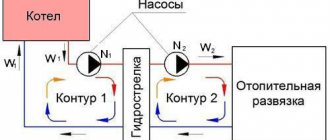
Until the coolant is heated to the required temperature (set by the boiler program), the water flow is “spinned” by the primary circuit circulation pump. Circulation pumps of secondary circuits are not connected. The coolant is directed along the hydraulic arrow from the hot side to the cold side (Q1 > Q2).
If the coolant reaches the set temperature, the secondary circuits of the heating system are activated. The coolant flows of the main and secondary circuits are equalized. In such conditions, the hydraulic arrow functions only as a filter and air vent (Q1 = Q2).
Functional diagram of the operation of a classic hydraulic switch for three different boiler operating modes. The diagram clearly indicates the distribution of heat flows for each individual operating mode of boiler equipment
If any part (for example, a heated floor circuit) of the heating system reaches a predetermined heating point, the selection of coolant by the secondary circuit temporarily stops. The circulation pump is turned off automatically, and the water flow is directed through the hydraulic arrow from the cold side to the hot side (Q1 < Q2).
Do-it-yourself hydraulic arrow made of polypropylene
Another popular material used in the manufacture of hydraulic arrows is polypropylene. We have already talked about it in the material DIY heating manifold. From a performance point of view, polypropylene is inferior to steel. After all, it is based on polyethylene, albeit of special strength, and it has the property of melting at high temperatures. In heating systems, parameters change constantly, and if this happens quickly and unexpectedly (for various reasons), then breakdowns cannot be avoided.
In addition, there are some nuances in welding polypropylene.
The pipe is also selected according to the rule of three diameters, which often leads to difficulties, especially in high-capacity heating systems. In this regard, polypropylene water guns are usually installed in low-power home boiler rooms.
Often in boiler rooms you can find a combined version - a steel hydraulic switch and polypropylene manifolds. Don’t forget, the wording of the names differs among different craftsmen and manufacturers. In video instructions, hydraulic arrows often appear, although in fact we are looking at ordinary combs.
The cost of a polypropylene hydraulic arrow is about 1 thousand rubles, provided that you have all the fittings and a welding machine.
conclusions
In this article we looked at various ways to make a hydraulic arrow with your own hands. The first, steel ones, are widely in demand among specialists due to their wear resistance and functionality. Second, polypropylene arrows are cheaper. However, they are not as reliable as metal ones (they can break due to temperature differences).
The sectional structure of the hydraulic arrow is the same in most homemade products. Hydroshooters produced by specialized companies have a more advanced device. As for the alternative, here again it is worth paying attention to the products of manufacturers. In any case, proceed from your resources and acquired skills, but remember, a free couple of hours can turn into a day or a week.
Do-it-yourself hydraulic arrow for heating made of steel
In order to work with metal, you need certain skills and abilities. Have you decided to make a homemade hydraulic arrow from steel? Then you should approach this process with all seriousness and responsibility.
The first difficulties you will have to face are choosing a steel grade. Many users believe that they can use any piece of pipe that is unnecessarily lying in your garage or storage room. However, this is a deep misconception. The service life of the hydraulic separator and its appearance will directly depend on the quality of the base used. Experts advise giving preference to stainless or structural steel. Both brands are produced and sold in sheets; it is quite difficult for a novice master to work with them, so you should take a closer look at steel pipes.
Many experienced installers use them as a basis. Let's look at the example of the work of the famous video blogger Vitaly Luzhetsky, who welded a hydraulic arrow from a metal pipe.
Blank for hydraulic arrow
The author took as a basis a pipe whose diameter is 76 mm along the inner circumference.
After a thorough inspection of the part, Vitaly began drilling holes to which the threads would be welded in the future.
We drill holes for fastening threaded connections.
The total number of outputs is 8. Two are needed to connect the boiler, and three each for supply and return.
The man welded a hydraulic arrow for heating his house with his own hands, because... The finished product could not be found. A double-circuit boiler was installed in the house; its efficiency was not enough to heat the house; it was decided to install an indirect heating boiler. It is impossible to connect it directly to the boiler, so the owner decided to make his own hydraulic separator from steel.
The next step is to arrange the components. Threads or “nipples” DN 20 ¾ with internal edging for the ability to weld to inlets and outlets and plugs for end holes. A ½ thread is mounted on top of the plug so that an automatic air vent can be connected. Then they proceed directly to the welding process. Initially, work is carried out with plug bowls.
Welding hydraulic arrow blanks
Uneven seams must be thoroughly cleaned or ground down using a grinder. A special composition is sprayed onto the seam, which reduces the electrification of the metal.
Cleaning the weld seams on the hydraulic arrow blank
The next step is to install and attach the thread
It is very important here that all diameters are accurate
Do-it-yourself hydraulic arrow grinding
Rough welding does not look very aesthetically pleasing, but all defects can be eliminated during the grinding process
Special attention should be paid to the junction areas (transition areas). If there are a large number of irregularities, then it is necessary to perform another auxiliary procedure - puttying
Initially, the body of the product must be primed and allowed to dry for several hours.
Primed hydraulic arrow
It is also worth remembering about crimping. Most often, the arrows are checked before finishing; the permissible range is 10-16 atm. Final painting is carried out only after all preparatory work has been completed. Spray paint is applied every fifteen minutes. A total of three layers need to be applied.
Painting the hydraulic arrow with spray paint
The cost of the product was about two thousand rubles.
https://youtube.com/watch?v=3_DKbbnHfOw
How residents can install a distributor: procedure
An owner who wants to reduce heating bills must begin by obtaining permission to install the device.
To do this, the owner should:
- Find out whether a thermal energy control unit is installed in an apartment building;
- Find out from the management company whether 50% or more of the apartments in your building are equipped with distributors;
- Coordinate the installation of distributors with the organization supplying energy resources. Obtain permission from the Management Company;
- Replace heating radiators with modern models. The use of old batteries and homemade registers is prohibited. Install thermostatic regulators that allow temperature adjustment to create a comfortable room microclimate;
- Installation of heat distributors is carried out by a certified specialist or developer, taking into account the heat distribution throughout the house;
- Concluding an agreement that details the procedure for taking readings, recalculation and the responsibilities of the parties.
Why do you need a hydraulic arrow?
If you plan to install a simple closed-type heating system in your house, where no more than 2 circulation pumps are used, then you definitely do not need a hydraulic separator.
When there are three circuits and pumps, and one of them is designed to work with an indirect heating boiler, then here too you can do without a hydraulic arrow. You need to think about separating heating circuits in a situation where the diagram looks like this:
There is no hydraulic arrow in the presented diagram, but its installation is clearly indispensable. There are 4 circuits in which the same number of pumps of different capacities operate. The most powerful of them will create a vacuum in the supply manifold, and increased pressure in the return manifold. When operating simultaneously, a pump with a lower capacity simply does not have enough strength to overcome this vacuum and it will not be able to take the coolant to its circuit. As a result, the branch will not function because the pumps interfere with each other.
To eliminate the pressure difference ΔP that occurs between the collectors and to enable all pumps to calmly extract the required amount of coolant, a hydraulic arrow is included in the circuit. It is a hollow pipe with a design cross-section, whose task is to create a zone of zero pressure between the heat generator and several consumers. How this element works in the boiler piping circuit is described in the next section.
Alternative options
The water gun is sometimes replaced with a bypass or dispensed with, which is important in boiler houses with a small number of consumers. It makes more sense to replace homemade products with products under warranty, that is, hydraulic guns manufactured according to an approved drawing. At first glance, this may not seem financially beneficial.
But here’s how you look: when you set out to do it yourself, bring it to the end. And if you don’t have time, but the desire to make heating in your home according to all the rules has not disappeared, then it is wiser to choose a manufacturer with experience and a good range of models. Our company found one, and it’s great luck that it’s domestic. The Gidruss industrial group has been operating on the market since 2012, and during this time it has taken one of the leading positions in its segment. The brand's product line includes more than a hundred devices designed to ensure optimal distribution of coolant throughout the system. If you want to learn more about the characteristics, see photos or compare prices, welcome to the catalog pages.
Location of the house on a narrow plot
The location of the house can be determined by the location of the access road to the site and how communications pass. It is much easier and cheaper to erect a building next to them than to pull them across a significant part of the site.
If, for example, it is possible to provide a road from any side, and most of the communications are autonomous, then you can choose the place for the house yourself.
Option for house location on siteSource wp.com
Location of the house at the end of the siteSource rego-stroy.ru
If the plot is not too long, it is better to build a residential building at one of its ends. This will visually cut off the excess length of the territory, the remaining space will be close to a square, which will greatly facilitate landscape design on it.
House in the middle of a long narrow plotSource homify.co.uk
If the plot is very long, then the house should be “broken” into halves or thirds and two-thirds. This arrangement, firstly, makes the area more harmonious visually, and secondly, it is very convenient.
- On one side of the house you can arrange a functional area with a vegetable garden, a barn and a greenhouse.
- And on the other, make a recreation area with flower beds, a lawn, gazebos, a pond, and so on.
When planning the location of the house, be sure to take into account the orientation of the site to the cardinal points. Buildings should not obscure a significant part of the land. It is also necessary to comply with legal standards regarding the distance from buildings to the boundaries of the site and buildings beyond its boundaries.
Price
The price of products depends on several factors:
- power;
- volume;
- material;
- the number of circuits that need to be connected;
- manufacturer's company;
- promotion of the brand.
Approximate cost of domestically produced hydraulic arrows:
- NORTH-60 , power up to 50 kW – 2560 rubles;
- SEVER-220 , power up to 500 kW – 25,500 rubles;
- Gidruss GR-150-40 , power up to 150 kW – 8300 rubles.
- Warme WGR80 with outlets for an air valve and a mud pan, with a power of up to 80 kW - from 3,700 rubles, with a power of up to 122 kW - from 6,000 rubles.
Approximate cost of foreign-made hydraulic arrows:
- Meibes MHK 32 with power up to 70 kW – 13,800 rubles (manufacturer Germany).
- Bosch HW 50 with power up to 105 kW – 12,000 rubles (manufacturer Germany).
Operation of the hydraulic gun in different modes.
There are three main modes in which the hydraulic separator
.
Depending on the switching on and off of heating system consumers, the operating mode of the hydraulic switch
or
modular type hydraulic switch
(hydraulic switch + manifold) also changes.
So what happens after launch? After starting the heating system, until the coolant has reached the required temperature, the liquid circulates in a small circle and the entire flow moves down the hydraulic arrow
.
After the temperature of the coolant reaches the required operating mode of the hydraulic separator, into the secondary heating circuit, with uniform analysis, when equalizing the incoming and outgoing flows, the hydraulic arrow
works as
an air vent
and cleans the coolant from dirt.
Note that it is practically impossible to achieve complete equality between the two flows, hence the 100 percent feasibility of installing a hydraulic arrow.
When heating the room, the automation regulates the coolant flow in the secondary circuit, for example, if a certain DHW temperature is reached, the pump in this circuit is turned off, or if the radiator thermal heads reduce the coolant flow, which in turn increases the hydraulic resistance in the heating circuit, which is monitored by an adaptive pump - thus, adapting to this and reducing its productivity, as a result the total flow of Q2 decreases. As a result, the difference between the two flows (primary and secondary) goes up the hydraulic needle. If the hydraulic valve had not been installed, significant hydraulic imbalances would have occurred in the heating system, and as a result, failure of the heating equipment (pump, heat exchanger). What happens if the consumer circulation pumps stop, then the primary circuit of the heating system goes into mode 3.
Figures 3-5 show these modes:
Figure 3:
The total flow rate of the boiler pumps is equal to the total flow rate of the heating system pumps. This mode is rarely achieved. In this case, all the coolant heated by the boiler enters the heating system to consumers.
Figure 4:
The total flow rate of the boiler pump is less than the total flow rate of the heating circuit pumps. This mode is possible when the boiler cannot cope with the load. In this case, the boiler operates in maximum mode and constantly heats the coolant.
If there are several boilers, the total flow rate of the boiler pumps is less than the total flow rate of the heating circuit pumps. In this mode, one of several boilers and its pump is turned off, since the operation of one boiler is enough, while the heating circuit pumps take the necessary coolant from the heating return pipe through a hydraulic valve. Thus, the flow rate in the boiler circuit remains constant, corresponding to the required value for the operation of the boiler.
Figure 5:
The total flow rate of the heating circuits is less than the flow rate provided by the boiler pumps. The most common mode in which boiler pumps are selected correctly and have a slightly higher flow rate than required by the heating system. This mode provides all the necessary conditions for the heating system to operate in the boiler’s economical mode.
. In this embodiment, the hydraulic arrow plays a protective role for boilers, since the addition of hot coolant in the hydraulic arrow creates a minimum temperature difference in the boiler return line, and the required amount of coolant enters the heating circuit. This mode is the most optimal, so it is adopted when designing the system.
The power of the hydraulic switch must be higher than the total power of the boiler used.
Installation location
For proper installation of hydraulic arrows, follow 5 general rules:
- For proper operation of the distributor, it does not matter in what position the hydraulic arrow is installed. The only important thing is the direction of the end pipelines, on which the operation of the automatic air vent and the sludge removal system depend.
- The distributor is installed after the boiler valve. The installation location is determined by the heating circuit; it is located as close as possible to the unit.
- If a collector circuit is used, the distributor is placed in front of the boiler unit.
- If it is necessary to connect an additional electric pump, the distributor is placed between it and the outlet pipe for the heating circuit.
- In order to properly connect the solid fuel unit, the hydraulic arrow is connected to the coolant outlet and inlet, then you can adjust the individual temperature for each circuit.
