When several pumps operate simultaneously in the heating system of a private house for different consumers, it is necessary to ensure uniform distribution of the coolant. For this purpose, a special hydraulic separator is connected to the boiler equipment. Let's look at what a hydraulic arrow for heating is, what is its purpose, design, principle of operation, in what modes it can operate, how to correctly calculate its parameters and what are the features of its connection.
Modern boiler room with hydraulic switch Source san-kras.ru
What it is
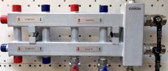
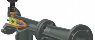
For those who are faced with the need to properly distribute coolant throughout the system when there are several pumps for different consumers, a natural question arises about what a hydraulic pump is. Externally, this device is a metal vertical container in the form of a large pipe with several side pipes of smaller diameter. There are also two tubes at the base and top. The top one is designed to bleed off accumulated air, the bottom one is to remove sediment.
In addition to proper distribution of the coolant, the device ensures equalization of its heating parameters on the forward and return paths in the heating main. Such a mechanism can work optimally only if it fully complies with the characteristics of the heating system. Therefore, ideally, the hydraulic arrow should be designed and selected according to the parameters of volume, number and location of insertion of pipes in each specific case individually.
Hydraulic gun action diagram Source ytimg.com
However, in practice this requirement is rarely met. Often, universal models are installed into the system, which are widely available today - which, naturally, cannot but negatively affect the subsequent operation of the equipment.
The hydraulic arrow inside may contain a number of additional devices:
- Flow dividers.
- Filters for cleaning mechanical impurities.
- Dissolved air compartments.
In practice, not all of them are beneficial. For example, screens for cleaning solid particles quickly become clogged and first reduce the flow rate, and then completely make the system impassable.
Note! The hydraulic separator tank is made of pipes of both round and rectangular cross-section. However, round models are more effective, natural and in demand.
First rule
The most important rule that must always be followed is the so-called “rule of three diameters,” that is, the diameter of the hydraulic arrow you install must be three times larger than this parameter for the nozzles. If you want the hydraulic separator to be able to fully perform its main functions, that is:
- separate sludge from the system;
- remove gases;
- equalize hydraulic differences;
- supply heated water to the boiler to ensure its greater durability.
Many people prefer to save money and make hydraulic arrows themselves from polypropylene, but in fact this is an absolutely wrong decision, made mainly by people who have little understanding of the operating features of such equipment.
It is for this reason that it is worth using only full-fledged metal pipes, which allow you to fully realize the potential of such technology and will truly show themselves effectively throughout the entire life of such a system.
Device, principle of operation, purpose
A complete understanding of what a hydraulic arrow for heating is, why it is needed, what its varieties are, can be obtained by considering its detailed structure, principles of operation and purpose. Let's look at these aspects in more detail.
An example of a heating scheme for a private house with a hydraulic arrow Source project-home.ru
See also: Catalog of companies that specialize in engineering systems (heating, water supply, sewerage and others) and related work
Device
Structurally, the hydraulic separator is a hollow container of round or square cross-section closed at the ends. Its dimensions depend primarily on the power of the boiler, as well as the number and capacity of the circuits. Depending on the weight, the structure is either installed on the floor using support legs, or mounted on the wall surface using a special bracket.
Working pipes, the number of which, as a rule, is at least 4, are connected to the heat pipe via threads or using flanges. The material used to make the device is very different - ordinary steel with low carbon content, stainless alloy, copper, and polypropylene. At the same time, systems operating on a solid fuel unit are equipped only with metal models.
Although the vertical position of the device is considered traditional, it is not mandatory. For example, when eliminating air pockets and filtering sediment from the coolant is not a necessary condition, a horizontal arrangement of the device is possible. In this case, the need for convection mixing of flows is eliminated.
Hydraulic separator device Source vodoteplo.ru
Principle of operation
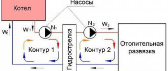
Uniform distribution of the coolant in the presence of several consumers at the same time is ensured by a hydraulic arrow for heating - the operating principle of such a mechanism is based on dividing the total flow into independent directions for each individual circuit. If the circulation pump of boiler equipment accelerates water to 1 m/s, then in the hydraulic separator it slows down to a minimum of 0.1 m/s. In this case, several conditions are simultaneously met:
- The volume and direction of flow changes.
- Loss of thermal energy is eliminated.
- Hydraulic resistance is eliminated.
- The contours of the unit and the chain of consumers are separated - the hydraulic arrow acts as a buffer area.
- The pumping equipment for each circuit operates independently without affecting the overall hydraulic balance.
When several pumps are installed in the system, then a hydraulic separator for heating is connected, the operating principle of which is to ensure the correct operation of each circuit separately:
- Separate branches with radiators.
- Water heated floor.
- Indirectly heated boiler.
- Warm ventilation, etc.
Diagram of a hydraulic separator Source teplo.guru
As an example, we can consider a situation where several pumps are used that differ greatly in power. As a rule, all equipment is located in one room, the collector module. Turning on the most powerful pump will cause the pumping of all the coolant and deprivation of the remaining circuits. A simplified way to solve this problem is to install a hydraulic separator. Without it, all the pumps would have to be placed at a great distance from each other.
Popular manufacturers
There are not as few companies involved in the production of hydraulic separators for heating networks as it might seem at first glance. However, today we will get acquainted with the products of only two companies, GIDRUSS and Atom LLC, since they are considered the most popular.
Table. Characteristics of hydraulic separators manufactured by GIDRUSS.
| 1. GR-40-20 | — the product is made of structural steel; — designed for one consumer; — minimum power of the heating device is 1 kilowatt; — its maximum power is 40 kilowatts. |
| 2. GR-60-25 | — the product is made of structural steel; — designed for one consumer; — the minimum power of the heating device is 10 kilowatts; — its maximum power is 60 kilowatts. |
| 3. GR-100-32 | — the product is made of structural steel; — designed for one consumer; — minimum power of the heating device is 41 kilowatts; — its maximum power is 100 kilowatts. |
| 4. GR-150-40 | — the product is made of structural steel; — designed for one consumer; — minimum power of the heating device is 61 kilowatts; — its maximum power is 150 kilowatts. |
| 5. GR-250-50 | — the product is made of structural steel; — designed for one consumer; — the minimum power of the heating device is 101 kilowatts; — its maximum power is 250 kilowatts. |
| 6. GR-300-65 | — the product is made of structural steel; — designed for one consumer; — minimum power of the heating device is 151 kilowatts; — its maximum power is 300 kilowatts. |
| 7. GR-400-65 | — the product is made of structural steel; — designed for one consumer; — minimum power of the heating device is 151 kilowatts; — its maximum power is 400 kilowatts. |
| 8. GR-600-80 | — the product is made of structural steel; — designed for one consumer; — minimum power of the heating device is 251 kilowatts; — its maximum power is 600 kilowatts. |
| 9. GR-1000-100 | — the product is made of structural steel; — designed for one consumer; — minimum power of the heating device is 401 kilowatts; — its maximum power is 1000 kilowatts. |
| 10.GR-2000-150 | — the product is made of structural steel; — designed for one consumer; — minimum power of the heating device is 601 kilowatts; — its maximum power is 2000 kilowatts. |
| 11. GRSS-40-20 | — the product is made of AISI 304 stainless steel; — designed for one consumer; — minimum power of the heating device is 1 kilowatt; — its maximum power is 40 kilowatts. |
| 12. GRSS-60-25 | — the product is made of AISI 304 stainless steel; — designed for one consumer; — the minimum power of the heating device is 11 kilowatts; — its maximum power is 60 kilowatts. |
| 13. GRSS-100-32 | — the product is made of AISI 304 stainless steel; — designed for one consumer; — minimum power of the heating device is 41 kilowatts; — its maximum power is 100 kilowatts. |
Operating modes
To understand why a hydraulic arrow is needed in a heating system from a technical point of view, it is necessary to consider the main options for its application in practice. The following three schemes are distinguished:
- Equilibrium operation of the system. The hydroseparator operates in neutral mode without affecting the system. In this case, the pumping equipment of the heating unit pumps the same amount of coolant as is required for the heating system. At the same time, the indicators of heating, pressure, flow and generated heat correspond to theoretical calculations - both on the supply and return lines. However, in reality such conditions never arise, since after a short time all the characteristics of the system undergo changes.
3 operating modes of the hydraulic gun Source stroychik.ru
- The heating circuit consumes more coolant than the heat exchanger. This is the most common situation that arises in practice when the hydraulic separator works for its intended purpose. Vertical redistribution flows arise in it - from the return the coolant is mixed into the supply. There is a threat of heat stroke, since the lack of a thermal agent activates sensors, which in turn send a command to increase the operation of the heat generator. In this case, the consumer will still not receive the required amount of heat.
Specific example of an imbalance in a heating circuit
Suppose we have a heating circuit with 4 circuits, united by a common manifold, and the same number of zone pumps that supply water to the areas of its consumption.
When changing the number of zone pumps or their characteristics, the system will inevitably face the consequences of the mutual influence of each pump on all the others.
This will show up:
- in a drop in the productivity of each pump;
- in breakdowns and premature wear of equipment due to strong pressure drops;
- in a mode of operation of the entire system that differs from the norm. A general decrease in its efficiency, inefficiency and imbalance;
- in overheating of radiators, the temperature of which is higher than normal even when the pumps included in this particular circuit are turned off;
- in the increased likelihood of thermal shock, as well as in other problems that a manifold with a hydraulic arrow is designed to solve.
Read the article about making a hydraulic arrow for heating with your own hands here.
Video description
Video about what a hydraulic gun is and how it works:
- The flow of the heat exchange circuit is stronger than that of the heating circuit. This is the most optimal and correct option for operating a heating system with a well-designed and installed hydraulic valve. The flow required by the consumer is less than the flow supplied by the boiler. In this mode, a portion of the hot coolant is returned to the unit, so it will operate at a normal or even slightly reduced volume.
Important! The presence of a hydraulic arrow is mandatory in the heating system when several boilers are connected simultaneously in a cascade. In addition, it is needed for a unit equipped with a cast iron heat exchanger. Since the large difference between the heating of the outgoing and cooling of the incoming coolant flow leads to gradual cracking of the material.
Selection of hydraulic arrows
The main point when choosing a hydraulic arrow is the diameter, since the height does not play a special role. The larger the volume of the device, the better and better the temperature equalization occurs, which is especially in demand for boilers with solid fuel (coal, pallets, firewood).
When choosing a suitable model, you need to consider how many circuits will be connected to it. To find out the best option, you should determine the power of the circuit, as well as the volume of coolant. For this purpose, a hydraulic engineering calculation is carried out.
Video description
Video about the hydraulic separator and its purpose:
The calculation is carried out in the following several ways:
- Maximum coolant flow rate.
Calculated by the formula:
D = 3*d*√Mp/Vd
D is the diameter of the hydraulic needle, d is the diameter of the nozzle, MP is the maximum flow for the boiler, Vd is the maximum speed (0.2 m/s).
For example:
7*3*√8/02 = 21*√40 = 21*6.32 = 132.8 cm – 133 cm – diameter of the hydraulic needle.
The diameter of the pipe is 7 cm, the boiler flow rate is 8 cubic meters per hour.
- Highest boiler power.
The calculation is carried out using a similar formula:
D = 3*d*√Mk/(Vd * Traz)
However, some replacement parameters appear in it:
Mk – maximum boiler power, for example 60 kW,
Traz – the difference in heating of the coolant in the supply and return flows, for example 15 degrees.
For example:
21*√60/(02 * 15) = 21*4.4 = 94 cm.
- The length of the body of the hydraulic needle itself. The length of the device depends on the diameter and location of the pipes. Below is a diagram for calculating the characteristics. In the first version it will be equal to 12 diameters, in the second - 13.
Scheme for calculating the length of the hydraulic arrow according to the location of the pipes Source stroychik.ru
Advice! When calculating the parameters of a hydraulic arrow, it is important to determine the maximum possible coolant speed. If the flow moves quickly enough, a characteristic noise will arise in the system, significantly reducing the comfort in the house. Therefore, in order to avoid this negative effect, this parameter is limited to a value not exceeding 0.2 m/s.
Equipment and characteristic differences of hydraulic guns
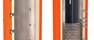
The separator kit depends on the internal content and the number of circuits for which it is designed. A mandatory element is an automatic air vent 1/2, equipped with a check valve or ball valve. For custom installations, removable thermal insulation is included.
Hydraulic guns of the GS type have built-in elements to eliminate air and sludge. The MGS (multifunctional hydraulic guns) kit contains magnetic rods and the ability to adjust the support height within 10 cm. Devices such as GS, MGS, flexbalance and maibes can be used for dual-circuit systems, but they can be equipped with a manifold.
Connection features
Knowing what a hydraulic valve is in a heating system allows you to correctly select it according to its parameters and correctly connect it. Installation of the device is carried out according to the general rules of plumbing installation. The device must first of all be correctly selected according to the main parameters - throughput, number of pipes, dimensions.
It is also necessary to remember what a hydraulic arrow is - the operating principle of this device is based on forced circulation. The system must have at least two pumps. One of them ensures the operation of the heat exchange circuit of the boiler, the other – the consumer system. If this condition is not met, the device will not only be useless, but even harmful and will act as an obstacle to the movement of the coolant.
Hydraulic separator without filter
The design of the arrow, which excludes the presence of the functions of an air separator and a sediment filter, also deviates somewhat from the accepted standard. Meanwhile, with such a design it is possible to obtain two flows with different speeds (dynamically independent circuits).
A non-standard design solution for the manufacture of hydraulic arrows. It differs from the classics in that there are no filtration or air removal functions. In addition, the distribution of heat flows has a perpendicular transport pattern, which achieves speed decoupling
For example, there is the heat flow of the boiler circuit and the heat flow of the heating device (radiator) circuit. With a non-standard design, where the direction of flow is perpendicular, the flow rate of the secondary circuit with heating devices increases significantly.
On the contrary, movement along the contour of the boiler is slower. True, this is a purely theoretical view. It is practically necessary to test under specific conditions.
Briefly about the main thing
A hydraulic separator for heating is a metal closed container with pipes mounted in front of the boiler. Designed for optimal distribution of coolant between consumers, as well as regulation of the heating level between forward and reverse flows in heating systems with forced circulation and at least 2 pumps. The need to install the device arises when the following consumers are simultaneously present:
- Separate radiator lines.
- Water heated floor system.
- Boiler operating on a heating boiler.
- Warm water ventilation.
The device is also needed to smooth out the effects of temperature changes on the cast iron heat exchanger. In this case, the hydraulic arrow can operate in three modes - in equilibrium, with insufficient power of the heating circuit and its superiority over the consumer. The last option is the most optimal. Before installation, the device must be calculated in terms of throughput, diameter and length, depending on the diameter and location of the connected pipes.
Is it possible to install one pump per circuit?
It would seem quite logical to equip each heating circuit with its own circulation pump that meets all the necessary parameters in order to solve the problem. Is it so? Unfortunately, even in this case the problem will not be solved - it will simply move to another level! Indeed, for the stable functioning of such a system, an accurate calculation of each pump is necessary, but even with this, a complex multi-circuit system will not become equilibrium. Each pump here will be associated with its own circuit, and its characteristics will change (that is, they will not be stable). In this case, one of the circuits can fully operate, and the second can be turned off. Due to circulation in one circuit, inertial movement of the working fluid may occur in an adjacent circuit, where this is not required at all (at least for the moment). And there can be a lot of such examples.
