Here you will learn:
- Types of heating systems
- Determination of coolant flow and pipe diameters
- Definition of resistance
- Hydraulic calculation table for water heating systems
- Hydraulic linkage
- Definition of losses
- Heat generator power
- Dynamic parameters of the coolant
- Overview of hydraulic calculation programs
- Hydraulic calculation of a heating system - calculation example
- Example calculation in Excel
The coolant circulates through the system under pressure, which is not a constant value. It is reduced due to the presence of friction forces of water against the walls of pipes, resistance on pipe fittings and fittings. The homeowner also makes his contribution by adjusting the heat distribution in individual rooms.
The pressure increases if the heating temperature of the coolant rises and, vice versa, drops when it decreases.
To avoid imbalance of the heating system, it is necessary to create conditions under which each radiator receives as much coolant as is necessary to maintain the set temperature and replenish the inevitable heat losses.
The main goal of hydraulic calculation is to bring the calculated network costs into line with the actual or operational ones.
At this design stage the following is determined:
- pipe diameter and capacity;
- local pressure losses in individual sections of the heating system;
- hydraulic linkage requirements;
- pressure loss throughout the system (total);
- optimal coolant flow.
To perform a hydraulic calculation, it is necessary to do some preparation:
- Collect initial data and systematize them.
- Select a calculation method.
First of all, the designer studies the thermal parameters of the object and performs a thermal calculation. As a result, he has information about the amount of heat required for each room. After this, heating devices and a heat source are selected.
Schematic illustration of a heating system in a private house
At the development stage, a decision is made on the type of heating system and the features of its balancing, pipes and fittings are selected. Upon completion, an axonometric wiring diagram is drawn up, floor plans are developed indicating:
- radiator power;
- coolant flow;
- placement of heating equipment, etc.
All sections of the system, nodal points are marked, the length of the rings is calculated and plotted on the drawing.
Types of heating systems
Engineering calculation tasks of this kind are complicated by the high diversity of heating systems, both in terms of scale and configuration. There are several types of heating junctions, each of which has its own laws:
1. A two-pipe dead-end system is the most common version of the device, well suited for organizing both central and individual heating circuits.
Two-pipe dead-end heating system
2. The single-pipe system or “Leningradka” is considered the best way to install civil heating systems with a thermal power of up to 30–35 kW.
Single-pipe heating system with forced circulation: 1 - heating boiler; 2 - security group; 3 - heating radiators; 4 — Mayevsky crane; 5 - expansion tank; 6 - circulation pump; 7 - drain
3. A two-pipe system of the associated type is the most material-intensive type of decoupling of heating circuits, which is distinguished by the highest known stability of operation and quality of coolant distribution.
Two-pipe associated heating system (Tichelman loop)
4. Beam distribution is in many ways similar to a two-pipe train, but at the same time, all system controls are located at one point - at the collector unit.
Radial heating circuit: 1 - boiler; 2 - expansion tank; 3 - supply manifold; 4 — heating radiators; 5 — return manifold; 6 - circulation pump
Before we get into the application side of the calculations, we need to make a couple of important warnings. First of all, you need to understand that the key to high-quality calculations lies in understanding the principles of operation of liquid systems on an intuitive level. Without this, consideration of each individual outcome turns into an interweaving of complex mathematical calculations. Secondly, it is practically impossible to present more than basic concepts within one review; for more detailed explanations, it is better to refer to the following literature on the calculation of heating systems:
- Pyrkov V.V. “Hydraulic control of heating and cooling systems. Theory and practice" 2nd edition, 2010
- R. Yaushovets “Hydraulics is the heart of water heating.”
- Manual “Hydraulics of Boiler Houses” from De Dietrich.
- A. Savelyev “House heating. Calculation and installation of systems.”
Briefly about the main thing
Designing heating systems allows you to select the optimal parameters: sufficient water supply, suitable pipe characteristics, pressure of circulation pumps. Hydraulic calculation is one of the most important parts of design. It allows you to balance the selected type of heating system, ensures its stable operation and durable use.
In hydraulic calculations, parameters such as pressure drop, water flow, and pipe diameter for each section are determined. A small system for a private home can be calculated manually (using formulas and reference books) or using an online calculator. For complex and powerful heating circuits, it is advisable to use specialized programs.
Determination of coolant flow and pipe diameters
First, each heating branch must be divided into sections, starting from the very end. The breakdown is done by water consumption, and it varies from radiator to radiator. This means that after each battery a new section begins, this is shown in the example presented above. We start from the 1st section and find the mass flow rate of the coolant in it, focusing on the power of the last heating device:
G = 860q/ ∆t, where:
- G – coolant flow, kg/h;
- q – thermal power of the radiator in the area, kW;
- Δt – temperature difference in the supply and return pipelines, usually 20 ºС.
For the first section, the coolant calculation looks like this:
860 x 2 / 20 = 86 kg/h.
The result obtained must be immediately plotted on the diagram, but for further calculations we will need it in other units - liters per second. To make a translation, you need to use the formula:
GV = G /3600ρ, where:
- GV – volumetric water flow, l/sec;
- ρ – density of water, at a temperature of 60 ºС is equal to 0.983 kg / liter.
We have: 86 / 3600 x 0.983 = 0.024 l/sec. The need to convert units is explained by the need to use special ready-made tables to determine the diameter of a pipe in a private house. They are freely available and are called “Shevelev tables for hydraulic calculations.” You can download them by following the link: https://dwg.ru/dnl/11875
These tables show the diameters of steel and plastic pipes depending on the flow rate and speed of the coolant. If you open page 31, then in Table 1 for steel pipes the first column shows the flow rate in l/sec. In order not to make a full calculation of pipes for the heating system of a private home, you just need to select the diameter according to the flow rate, as shown in the figure below:
Note. In the left column, under the diameter, the speed of water movement is immediately indicated. For heating systems, its value should be in the range of 0.2–0.5 m/sec.
So, for our example, the internal passage size should be 10 mm. But since such pipes are not used in heating, we can safely accept a DN15 (15 mm) pipeline. We put it on the diagram and move on to the second section. Since the next radiator has the same power, there is no need to apply formulas; we take the previous water flow and multiply it by 2 and get 0.048 l/sec. We turn to the table again and find the closest suitable value in it. At the same time, do not forget to monitor the water flow speed v (m/sec) so that it does not exceed the specified limits (in the figures it is marked in the left column with a red circle):
Important. For heating systems with natural circulation, the coolant movement speed should be 0.1-0.2 m/sec.
As can be seen in the figure, section No. 2 is also laid with a DN15 pipe. Next, using the first formula, we find the flow rate in section No. 3:
860 x 1.5 / 20 = 65 kg/h and convert it to other units:
65 / 3600 x 0.983 = 0.018 l/sec.
Adding it to the sum of the costs of the two previous sections, we get: 0.048 + 0.018 = 0.066 l/sec and again turn to the table. Since in our example we are not calculating a gravitational system, but a pressure one, then in terms of coolant speed, a DN15 pipe is suitable this time too:
Following this path, we calculate all the areas and plot all the data on our axonometric diagram:
Summarizing
It has already been said above that hydraulic calculation of a heating system is a complex task that requires professional knowledge. If you have to design a highly ramified heating system (large house), then manual calculations take a lot of effort and time. To simplify this task, special computer programs have been developed.
Sergei Bulkin
Using these programs, you can make hydraulic calculations, determine the adjustment characteristics of shut-off and control valves, and automatically create a custom specification. Depending on the type of program, calculations are carried out in the AutoCAD environment or in your own graphic editor.
Let us add that now, when designing industrial and civil facilities, there is a tendency to use BIM technologies (building information modeling). In this case, all designers work in a single information space. For this purpose, a “cloud” model of the building is created. Thanks to this, any inconsistencies are identified at the design stage, and the necessary changes are made to the project in a timely manner. This allows you to accurately plan all construction work, avoid delays in the completion of the project and thereby reduce the estimate.
Definition of resistance
Engineers are often faced with calculations of heat supply systems for large facilities. Such systems require a large number of heating devices and hundreds of linear meters of pipes. You can calculate the hydraulic resistance of a heating system using equations or special automated programs.
To determine the relative heat loss for adhesion in the line, the following approximate equation is used: R = 510 4 v 1.9 / d 1.32 (Pa/m). The use of this equation is justified for speeds of no more than 1.25 m/s.
If the value of hot water consumption is known, then an approximate equation is used to find the cross-section inside the pipe: d = 0.75 √G (mm). After receiving the result, you will need to refer to a special table to obtain the cross-section of the nominal diameter.
The most tedious and labor-intensive calculation will be the calculation of local resistance in the connecting parts of the pipeline, control valves, gate valves and heating devices.
Integration
To calculate heating networks, the program includes the ability to automatically construct piezometric graphs in MS Excel based on the calculation results.
Watch the video
The program provides the ability to import pipeline diagrams from various graphic design systems via a PCF file, import from projects and export to START program projects, import from open format files (with which you can configure the import of data into the program from any object-oriented model). Along with the program, a module is supplied for downloading data from the PDMS program into open format files for subsequent import into the Hydraulic System. It is also possible to export the pipeline diagram to DXF format.
Hydraulic linkage
Balancing pressure drops in the heating system is carried out using control and shut-off valves.
Hydraulic linking of the system is carried out on the basis of:
- design load (coolant mass flow);
- data from pipe manufacturers on dynamic resistance;
- the number of local resistances in the area under consideration;
- technical characteristics of fittings.
Installation characteristics - pressure drop, fastening, throughput - are set for each valve. They are used to determine the coefficients of coolant flow into each riser, and then into each device.
Pressure loss is directly proportional to the square of the coolant flow rate and is measured in kg/h, where
S is the product of dynamic specific pressure, expressed in Pa/(kg/h), and the reduced coefficient for local resistance of the section (ξpr).
The given coefficient ξpr is the sum of all local resistances of the system.
Valtec “Sputnik” equipment configurator
Configurator software is a modular configurator for various metering devices and equipment. Allows commissioning of the Valtec “Sputnik” automated energy metering system.
- The configurator includes the following modules:
- polling of metering devices via radio channel using radio modem VT.WRM.MASTER.0
- module for reading data from VT.WRM hubs
- module for configuring wireless pulse counter-recorder GSM/GPRS VT.WLR.GSM
- module for configuring a wireless pulse counter-recorder with a radio channel (LoRAWAN 868 MHz) VT.LR
- module for configuring pulse counter-recorder SIPU (RS485/M-Bus) VT.MB/ VT.RS
Heat generator power
One of the main components of the heating system is the boiler: electric, gas, combined – it doesn’t matter at this stage. Because its main characteristic is important to us - power, that is, the amount of energy per unit of time that will be spent on heating.
The power of the boiler itself is determined by the formula below:
Wboiler = (Sroom*Wshare) / 10,
Where:
- Sroom – the sum of the areas of all rooms that require heating;
- Wdel – specific power taking into account the climatic conditions of the location (this is why it was necessary to know the climate of the region).
Typically, for different climatic zones we have the following data:
- northern regions – 1.5 – 2 kW/m2;
- central zone – 1 – 1.5 kW/m2;
- southern regions – 0.6 – 1 kW/m2.
These figures are quite arbitrary, but nevertheless provide a clear numerical answer regarding the influence of the environment on the apartment heating system.
This map shows climate zones with different temperature regimes. The location of the housing relative to the zone determines how much energy needs to be spent on heating a square meter of kWatt of energy (+)
The amount of the apartment area that needs to be heated is equal to the total area of the apartment and is equal, that is, 65.54-1.80-6.03 = 57.71 m2 (minus the balcony). The specific boiler power for the central region with cold winters is 1.4 kW/m2. Thus, in our example, the calculated power of the heating boiler is equivalent to 8.08 kW.
Example initial conditions
For a more specific explanation of all the details of the hydraulic calculation, let’s take a specific example of an ordinary living space. We have a classic 2-room apartment in a panel house with a total area of 65.54 m2, which includes two rooms, a kitchen, separate toilet and bathroom, a double corridor, a twin balcony.
After commissioning, we received the following information regarding the readiness of the apartment. The described apartment includes walls made of monolithic reinforced concrete structures treated with putty and primer, profile windows with two-chamber glass, pressed interior doors, ceramic tiles on the bathroom floor.
A typical 9-storey panel house with four entrances. There are 3 apartments on each floor: one 2-room and two 3-room. The apartment is located on the fifth floor
In addition, the presented housing is already equipped with copper wiring, distributors and a separate panel, a gas stove, a bathtub, a washbasin, a toilet, a heated towel rail, and a sink.
And most importantly, the living rooms, bathroom and kitchen already have aluminum heating radiators. The question regarding the pipes and boiler remains open.
Dynamic parameters of the coolant
We move on to the next stage of calculations - analysis of coolant consumption. In most cases, the heating system of an apartment differs from other systems - this is due to the number of heating panels and the length of the pipeline. Pressure is used as an additional “driving force” for flow vertically through the system.
In private one- and multi-story buildings, old panel apartment buildings, high-pressure heating systems are used, which makes it possible to transport the heat-releasing substance to all sections of the branched, multi-ring heating system and raise water to the entire height (up to the 14th floor) of the building.
On the contrary, an ordinary 2- or 3-room apartment with autonomous heating does not have such a variety of rings and branches of the system; it includes no more than three circuits.
This means that the coolant is transported using the natural process of water flow. But you can also use circulation pumps; heating is provided by a gas/electric boiler.
We recommend using a circulation pump for heating rooms larger than 100 m2. The pump can be installed either before or after the boiler, but usually it is installed on the “return” - lower fluid temperature, less airiness, longer pump life
Specialists in the field of design and installation of heating systems define two main approaches in terms of calculating the volume of coolant:
- According to the actual capacity of the system. Without exception, all volumes of cavities where the flow of hot water will flow are summed up: the sum of individual sections of pipes, sections of radiators, etc. But this is a rather labor-intensive option.
- According to boiler power. Here the opinions of experts differ greatly, some say 10, others 15 liters per unit of boiler power.
From a pragmatic point of view, you need to take into account the fact that probably the heating system will not only supply hot water for the room, but also heat water for the bath/shower, washbasin, sink and dryer, and maybe for a hydromassage or jacuzzi. This option is simpler.
Therefore, in this case, we recommend setting 13.5 liters per unit of power. Multiplying this number by the boiler power (8.08 kW) we obtain the estimated volume of water mass - 109.08 liters.
The calculated coolant velocity in the system is precisely the parameter that allows you to select a certain pipe diameter for the heating system.
It is calculated using the following formula:
V = (0.86*W*k)/t-to,
Where:
- W – boiler power;
- t – temperature of the supplied water;
- to – water temperature in the return circuit;
- k – boiler efficiency (0.95 for a gas boiler).
Substituting the calculated data into the formula, we have: (0.86 * 8080 * 0.95)/80-60 = 6601.36/20 = 330 kg/h. Thus, in one hour, 330 liters of coolant (water) move through the system, and the system capacity is about 110 liters.
How data is collected
The hydraulic calculation of the system is mostly based on calculations related to the calculation of heating based on the area of the room.
Therefore, it is necessary to have the following information:
- the area of each individual room;
- dimensions of window and door connectors (internal doors have practically no effect on heat loss);
- climatic conditions, features of the region.
We will proceed from the following data. Living room area - 18.83 m2, bedroom - 14.86 m2, kitchen - 10.46 m2, balcony - 7.83 m2 (total), corridor - 9.72 m2 (total), bathroom - 3.60 m2, toilet - 1.5 m2. Entrance doors - 2.20 m2, common room window - 8.1 m2, bedroom window - 1.96 m2, kitchen window - 1.96 m2.
The height of the apartment walls is 2 meters 70 cm. The external walls are made of class B7 concrete plus internal plaster, 300 mm thick. Internal walls and partitions - load-bearing 120 mm, ordinary - 80 mm. The floor and, accordingly, the ceiling are made of concrete floor slabs of class B15, thickness 200 mm.
The layout of this apartment provides the opportunity to create one single heating branch passing through the kitchen, bedroom and living room, which will ensure an average temperature of 20-22⁰C in the rooms (+)
What about the environment? The apartment is located in a house located in the middle of a microdistrict of a small town. The city is located in a certain lowland, the altitude above sea level is 130-150 m. The climate is moderate continental with cool winters and fairly warm summers.
Average annual temperature is +7.6°C. The average temperature in January is -6.6°C, in July +18.7°C. Wind - 3.5 m/s, average air humidity - 74%, precipitation 569 mm.
Analyzing the climatic conditions of the region, it should be noted that we are dealing with a wide range of temperatures, which in turn affects the special requirement for adjusting the heating system of the apartment.
Overview of hydraulic calculation programs
Essentially, any hydraulic calculation of water heating systems is considered a difficult engineering task. To solve this problem, a number of software packages have been developed that facilitate the implementation of such a procedure.
You can try to perform a hydraulic calculation of the heating system in Excel using ready-made formulas. However, the following problems may occur:
- Large error. In many cases, as an example of a hydraulic calculation of a heating system, diagrams with one or two pipes are taken. Finding the same calculations for the collector is problematic;
- To correctly account for resistance in terms of pipeline hydraulics, reference data is needed that is not included in the form. They must be searched for and entered additionally.
Taking such factors into account, experts recommend using calculation programs. A large number of them are paid, but some have a demo version with few features.
Oventrop CO
The most simple and clear program for hydraulic calculation of heating networks. An intuitive interface and flexible settings can help you quickly understand the invisible aspects of data entry. Small problems may appear when setting up the complex for the first time. You will need to enter all the parameters of the system, starting from the pipe material itself and ending with the placement of the TENS.
It is distinguished by flexible settings, the ability to make the simplest hydraulic calculation of heat supply both for a new heating network and for modernizing an old one. It stands out from its substitutes with a good graphical interface.
Instal-Therm HCR
The software package is calculated for professional resistance in terms of hydraulics of the heating network. The free version has a lot of contraindications. Area of use: design of heat supply in large public and industrial buildings.
In practical conditions, for autonomous heat supply of private apartments and houses, hydraulic calculations are not always done. However, this can lead to deterioration in the performance of the heating system and rapid breakdown of its components - heating devices, pipes and boiler. To avoid this, you need to calculate the system parameters in time and compare them with the actual ones for subsequent optimization of the heat supply operation.
HERZ CO
It is characterized by flexibility of settings, the ability to make simplified hydraulic heating calculations both for a new heating system and for modernizing an old one. It differs from analogues in its convenient graphical interface.
Microsoft Excel Developer Tool
Microsoft Excel for hydraulic calculations in heating networks is the most accessible tool for users. Its comprehensive spreadsheet editor can solve many computing problems. However, when performing calculations of thermal systems, special requirements must be met. These can be listed:
- finding the previous section in the direction of movement of the medium;
- calculation of the pipe diameter based on a given conditional indicator and reverse calculation;
- establishing a correction factor for the size of the specific pressure loss based on the data and the equivalent roughness of the pipe material;
- calculating the density of a medium from its temperature.
Of course, the use of Microsoft Excel for hydraulic calculations in heating networks does not make it possible to completely simplify the calculation process, which initially creates relatively large labor costs.
Software for hydromechanical calculations of networks or the GRTS package is a computer application that performs hydromechanical calculations of multi-pipe networks, including a dead-end configuration. The GRTS platform contains formula language functionality that allows you to establish the necessary calculation characteristics and select formulas for the accuracy of their determination. Due to the use of this functionality, the calculator has the opportunity to independently find the computing technology and set the required complexity.
There are two modifications of the GRTS application: 1.0 and 1.1. Upon completion, the user will receive the following results:
- calculation, in which the calculation methodology is carefully described;
- report in tabular form;
- transfer of computational databases to Microsoft Excel;
- piezometric graph;
- coolant temperature graph.
The GRTS 1.1 application is considered the most modern modification and supports the latest standards:
Hydraulic calculation of a heating system - calculation example
As an example, consider a two-pipe gravity heating system.
Initial data for calculation:
- design thermal load of the system – Qzd. = 133 kW;
- system parameters – tg = 750С, tо = 600С;
- coolant flow (calculated) – Vсо = 7.6 m3/h;
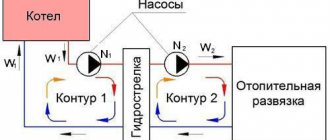
- The heating system is connected to the boilers through a horizontal hydraulic separator;
- the automation of each boiler maintains a constant temperature of the coolant at the outlet throughout the year - tg = 800C;
- an automatic differential pressure regulator is installed at the inlet of each distributor;
- The heating system from the distributors is mounted from metal-plastic pipes, and the heat supply to the distributors is carried out through steel pipes (water and gas).
The diameters of the pipeline sections were selected using a nomogram for a given coolant speed of 0.4-0.5 m/s.
A DN 65 valve is installed in section 1. Its resistance, according to the manufacturer’s information, is 800 Pa.
A filter with a diameter of 65 mm and a throughput capacity of 55 m3/h is installed in section 1a. The resistance of this element will be:
0.1 x (G/kv) x 2 = 0.1 x (7581/55) x 2 = 1900 Pa.
The resistance of a three-way valve dу = 40 mm and kv = 25 m3/h will be 9200 Pa.
The total pressure loss in the heat supply system of the distributors will be equal to 21514 Pa or approximately 21.5 kPa.
The remaining parts of the heat supply system for the distributors are calculated in a similar manner. When calculating the heating system, the main circulation ring through the most loaded heating device is selected from the distributor. Hydraulic calculations are made using the 1st direction.
Applications of the normative method
You may be interested in: Steel X12F1: characteristics and application
Hydraulics of networks is carried out on the basis of tables of maximum hourly heat loads and a heat supply diagram for a city or region, indicating the sources, location of the main, intra-block and intra-house engineering systems, indicating the boundaries of the balance sheet ownership of the network owners. Hydraulic calculation of heating network pipelines for each section up to the above diagram is carried out separately.
This calculation method is used not only for heating networks, but also for all pipelines transporting liquid media, including gas condensate and other chemical liquid media. For pipeline heat supply systems, changes must be made taking into account the kinematic viscosity and density of the media. This is due to the fact that these characteristics influence the specific pressure loss in the pipes, and the flow rate is related to the density of the transit medium.
VHM-T Service. Program for working with VALTEC heat meters
- The VHM-T Service program is designed to work with VALTEC VHM-T heat meters in terms of:
- reading current meter readings and characteristics;
- working with daily, monthly and annual archives;
- generation of thermal energy consumption accounting sheets;
- settings of date, time and automatic transition to summer/winter time (if necessary);
- counter settings for operation in automated data accounting systems.
Work computer software requirements
- operating system Windows XP Service Pack 3 (32/64 bit) or higher;
- Visual C++ Redistributable Packages for Visual Studio 2013 (free download available from microsoft.com). As a rule, these packages are already present in versions of Windows 7 and higher with the latest updates.
The interaction of the working computer with the heat meter is carried out through an optoelectronic sensor with the appropriate drivers installed in the system.
Setting up communication between the program and the meter
- Connect the optoelectronic sensor to the computer.
- On the front panel of the heat meter, press and hold the button (about 8 seconds) until the “=” symbol appears in the lower right corner of the screen.
- Bring the optoelectronic sensor to the opto-receiver of the meter on the front panel.
- Give a command to establish a connection in the program.
— Windows XP/Server 2003/Vista/7/8/8.1 (v6.7)
To activate the program, you must register again. The activation key is sent to the user's email address within 1-2 days.
If you have any questions about working with the program, you can ask them at:
Programs for old-style counters