Published on June 24, 2022 Category: Heat engineering | 32 comments
Calculating the hydraulic resistance of an individual pipeline and the entire system as a whole is a key task in hydraulics, the solution of which allows you to select pipe sections and a pump with the required pressure and flow rates in operating mode.
One of the earlier articles on the blog discussed a simple example of calculating a pipeline with parallel sections using the concept of “resistance characteristic”. At the end of the article I announced: “The accuracy of the method can be significantly improved...”. This phrase meant taking into account the dependence of resistance characteristics on flow more accurately. In that calculation, resistance characteristics were selected from tables based on pipe diameter and expected flow rate. Instead of tables, Vyacheslav Leonidovich Polkovov wrote custom functions in Excel for a more accurate calculation of hydraulic resistance, which he kindly provided for printing. The terms "resistance characteristic" and "hydraulic resistance" mean the same thing.
Formulation of the problem
Hydraulic calculations when developing a pipeline project are aimed at determining the diameter of the pipe and the pressure drop of the carrier flow. This type of calculation is carried out taking into account the characteristics of the structural material used in the manufacture of the pipeline, the type and number of elements that make up the pipeline system (straight sections, connections, transitions, bends, etc.), productivity, physical and chemical properties of the working environment.
Many years of practical experience in operating pipeline systems have shown that pipes with a circular cross-section have certain advantages over pipelines with a cross-section of any other geometric shape:
- the minimum ratio of perimeter to cross-sectional area, i.e. with equal ability to ensure media consumption, the cost of insulating and protective materials in the manufacture of pipes with a cross-section in the form of a circle will be minimal;
- the round cross-section is most advantageous for moving a liquid or gaseous medium from the point of view of hydrodynamics; minimal friction of the carrier against the pipe walls is achieved;
- the circular cross-sectional shape is maximally resistant to external and internal stresses;
- The process of making round pipes is relatively simple and affordable.
The selection of pipes by diameter and material is carried out on the basis of specified design requirements for a specific technological process. Currently, pipeline elements are standardized and unified in diameter. The determining parameter when choosing a pipe diameter is the permissible operating pressure at which the pipeline will be operated.
The main parameters characterizing the pipeline are:
- conditional (nominal) diameter – DN;
- nominal pressure – PN;
- working permissible (excessive) pressure;
- pipeline material, linear expansion, thermal linear expansion;
- physical and chemical properties of the working environment;
- complete set of pipeline system (branches, connections, expansion compensation elements, etc.);
- pipeline insulation materials.
The nominal diameter (bore) of a pipeline ( DN) is a conventional dimensionless value that characterizes the flow capacity of a pipe, approximately equal to its internal diameter. This parameter is taken into account when adjusting related pipeline products (pipes, bends, fittings, etc.).
The nominal diameter can have values from 3 to 4000 and is designated: DN 80 .
The nominal diameter, by numerical definition, approximately corresponds to the actual diameter of certain sections of the pipeline. Numerically, it is chosen in such a way that the throughput of the pipe increases by 60-100% when moving from the previous nominal passage to the next. The nominal diameter is selected according to the value of the internal diameter of the pipeline. This is the value that is closest to the actual diameter of the pipe itself.
Nominal pressure (PN) is a dimensionless quantity characterizing the maximum pressure of the working medium in a pipe of a given diameter, at which long-term operation of the pipeline is possible at a temperature of 20°C.
The nominal pressure values have been established based on long-term practice and operating experience: from 1 to 6300.
The nominal pressure for a pipeline with given characteristics is determined by the pressure closest to the one actually created in it. At the same time, all pipeline fittings for a given main must correspond to the same pressure. The pipe wall thickness is calculated taking into account the nominal pressure value.
How to work in EXCEL
Using Excel tables is very convenient, since the results of hydraulic calculations are always reduced to tabular form. It is enough to determine the sequence of actions and prepare exact formulas.
Entering initial data
Select a cell and enter a value. All other information is simply taken into account.
| Cell | Magnitude | Meaning, designation, unit of expression |
| D4 | 45,000 | Water consumption G in t/hour |
| D5 | 95,0 | Inlet temperature tin in °C |
| D6 | 70,0 | Outlet temperature tout in °C |
| D7 | 100,0 | Inner diameter d, mm |
| D8 | 100,000 | Length, L in m |
| D9 | 1,000 | Equivalent pipe roughness ∆ in mm |
| D10 | 1,89 | Sum coefficient local resistance - Σ(ξ) |
Explanations:
- the value in D9 is taken from the directory;
- the value in D10 characterizes the resistance at the welds.
Formulas and algorithms
We select cells and enter the algorithm, as well as the formulas of theoretical hydraulics.
| Cell | Algorithm | Formula | Result | Result value |
| D12 | !ERROR! D5 does not contain a number or expression | tср=(tin+tout)/2 | 82,5 | Average water temperature tav in °C |
| D13 | !ERROR! D12 does not contain a number or expression | n=0.0178/(1+0.0337*tavg+0.000221*tavg2) | 0,003368 | Kinematic coefficient water viscosity - n, cm2/s at tav |
| D14 | !ERROR! D12 does not contain a number or expression | ρ=(-0.003*tav2-0.1511*tav+1003, 1)/1000 | 0,970 | Average water density ρ,t/m3 at tav |
| D15 | !ERROR! D4 does not contain a number or expression | G'=G*1000/(ρ*60) | 773,024 | Water consumption G', l/min |
| D16 | !ERROR! D4 does not contain a number or expression | v=4*G:(ρ*π*(d:1000)2*3600) | 1,640 | Water speed v, m/s |
| D17 | !ERROR! D16 does not contain a number or expression | Re=v*d*10/n | 487001,4 | Reynolds number Re |
| D18 | !ERROR! Cell D17 does not exist | λ=64/Re at Re≤2320 λ=0.0000147*Re at 2320≤Re≤4000 λ=0.11*(68/Re+∆/d)0.25 at Re≥4000 | 0,035 | Hydraulic friction coefficient λ |
| D19 | !ERROR! Cell D18 does not exist | R=λ*v2*ρ*100/(2*9.81*d) | 0,004645 | Specific friction pressure loss R, kg/(cm2*m) |
| D20 | !ERROR! Cell D19 does not exist | dPtr=R*L | 0,464485 | Friction pressure loss dPtr, kg/cm2 |
| D21 | !ERROR! Cell D20 does not exist | dPtr=dPtr*9.81*10000 | 45565,9 | and Pa respectively D20 |
| D22 | !ERROR! D10 does not contain a number or expression | dPms=Σ(ξ)*v2*ρ/(2*9.81*10) | 0,025150 | Pressure loss in local resistance dPms in kg/cm2 |
| D23 | !ERROR! Cell D22 does not exist | dPtr=dPms*9.81*10000 | 2467,2 | and Pa respectively D22 |
| D24 | !ERROR! Cell D20 does not exist | dP=dPtr+dPms | 0,489634 | Calculated pressure loss dP, kg/cm2 |
| D25 | !ERROR! Cell D24 does not exist | dP=dP*9.81*10000 | 48033,1 | and Pa respectively D24 |
| D26 | !ERROR! Cell D25 does not exist | S=dP/G2 | 23,720 | Resistance characteristic S, Pa/(t/h)2 |
Explanations:
- the D15 value is recalculated in liters, this makes it easier to perceive the flow rate;
- cell D16 - add formatting according to the condition: “If v does not fall within the range of 0.25...1.5 m/s, then the cell background is red/the font is white.”
For pipelines with a difference in inlet and outlet heights, static pressure is added to the results: 1 kg/cm2 per 10 m.
Registration of results
The author's color scheme carries a functional load:
- Light turquoise cells contain the original data - they can be changed.
- Pale green cells are entered constants or data that is little subject to change.
- Yellow cells are auxiliary preliminary calculations.
- Light yellow cells—calculation results.
- Fonts: blue - original data;
- black - intermediate/non-main results;
- red - the main and final results of the hydraulic calculation.
Results in Excel table
Example from Alexander Vorobyov
An example of a simple hydraulic calculation in Excel for a horizontal pipeline section.
Initial data:
- pipe length 100 meters;
- ø108 mm;
- wall thickness 4 mm.
Table of results for calculating local resistances
By complicating the calculations in Excel step by step, you better master the theory and partially save on design work. Thanks to a competent approach, your heating system will become optimal in terms of costs and heat transfer.
Basic principles of hydraulic calculation
The working medium (liquid, gas, steam) carried by the pipeline being designed, due to its special physical and chemical properties, determines the nature of the flow of the medium in this pipeline. One of the main indicators characterizing the working medium is dynamic viscosity, characterized by the coefficient of dynamic viscosity - μ.
Engineer-physicist Osborne Reynolds (Ireland), who studied the flow of various media, conducted a series of tests in 1880, as a result of which the concept of the Reynolds criterion (Re) was derived - a dimensionless quantity that describes the nature of fluid flow in a pipe. This criterion is calculated using the formula:
The Reynolds criterion (Re) gives the concept of the ratio of inertial forces to viscous friction forces in a fluid flow. The value of the criterion characterizes the change in the ratio of these forces, which, in turn, affects the nature of the carrier flow in the pipeline. It is customary to distinguish the following modes of liquid carrier flow in a pipe depending on the value of this criterion:
- laminar flow (Re<2300), in which the carrier-liquid moves in thin layers that practically do not mix with each other;
- transition mode (2300
- turbulent flow (Re>4000) is a stable mode in which at each individual point of the flow there is a change in its direction and speed, which ultimately leads to equalization of the flow speed throughout the volume of the pipe.
The Reynolds criterion depends on the pressure with which the pump pumps the liquid, the viscosity of the media at operating temperature and the geometric dimensions of the pipe used (d, length). This criterion is a similarity parameter for fluid flow, therefore, using it, it is possible to simulate a real technological process on a reduced scale, which is convenient when conducting tests and experiments.
When carrying out calculations and calculations using equations, part of the given unknown quantities can be taken from special reference sources. Professor, Doctor of Technical Sciences F.A. Shevelev developed a number of tables for accurately calculating the pipe capacity. The tables include the values of parameters characterizing both the pipeline itself (dimensions, materials) and their relationship with the physical and chemical properties of the carrier. In addition, the literature provides a table of approximate values of the flow rates of liquid, steam, and gas in pipes of various sections.
Types of heating systems
Engineering calculation tasks of this kind are complicated by the high diversity of heating systems, both in terms of scale and configuration. There are several types of heating junctions, each of which has its own laws:
1. A two-pipe dead-end system is the most common version of the device, well suited for organizing both central and individual heating circuits.
Two-pipe dead-end heating system
2. The single-pipe system or “Leningradka” is considered the best way to install civil heating systems with a thermal power of up to 30–35 kW.
Single-pipe heating system with forced circulation: 1 - heating boiler; 2 - security group; 3 - heating radiators; 4 — Mayevsky crane; 5 - expansion tank; 6 - circulation pump; 7 - drain
3. A two-pipe system of the associated type is the most material-intensive type of decoupling of heating circuits, which is distinguished by the highest known stability of operation and quality of coolant distribution.
Two-pipe associated heating system (Tichelman loop)
4. Beam distribution is in many ways similar to a two-pipe train, but at the same time, all system controls are located at one point - at the collector unit.
Radial heating circuit: 1 - boiler; 2 - expansion tank; 3 - supply manifold; 4 — heating radiators; 5 — return manifold; 6 - circulation pump
Before we get into the application side of the calculations, we need to make a couple of important warnings. First of all, you need to understand that the key to high-quality calculations lies in understanding the principles of operation of liquid systems on an intuitive level. Without this, consideration of each individual outcome turns into an interweaving of complex mathematical calculations. Secondly, it is practically impossible to present more than basic concepts within one review; for more detailed explanations, it is better to refer to the following literature on the calculation of heating systems:
- Pyrkov V.V. “Hydraulic control of heating and cooling systems. Theory and practice" 2nd edition, 2010
- R. Yaushovets “Hydraulics is the heart of water heating.”
- Manual “Hydraulics of Boiler Houses” from De Dietrich.
- A. Savelyev “House heating. Calculation and installation of systems.”
Selection of the optimal pipeline diameter
Determining the optimal pipeline diameter is a complex production problem, the solution of which depends on a set of various interrelated conditions (technical and economic, characteristics of the working environment and pipeline material, technological parameters, etc.). For example, an increase in the speed of the pumped flow leads to a decrease in the diameter of the pipe that provides the media flow rate specified by the process conditions, which entails a reduction in material costs, cheaper installation and repair of the pipeline, etc. On the other hand, an increase in flow rate leads to a loss of pressure, which requires additional energy and financial costs for pumping a given volume of media.
The value of the optimal pipeline diameter is calculated using the transformed flow continuity equation, taking into account the given media flow:
In hydraulic calculations, the flow rate of the pumped liquid is most often specified by the conditions of the problem. The flow rate of the pumped medium is determined based on the properties of the given medium and the corresponding reference data (see table).
The transformed flow continuity equation for calculating the working diameter of the pipe has the form:
Conclusions and useful video on the topic
Features, advantages and disadvantages of natural and forced coolant circulation systems for heating systems:
Summarizing the hydraulic calculations, the result was specific physical characteristics of the future heating system.
Naturally, this is a simplified calculation scheme that provides approximate data regarding hydraulic calculations for the heating system of a typical two-room apartment.
Are you trying to do a hydraulic calculation of your heating system yourself? Or maybe you don’t agree with the material presented? We are waiting for your comments and questions - the feedback block is located below.
Calculation of pressure drop and hydraulic resistance
Total fluid pressure losses include losses for the flow to overcome all obstacles: the presence of pumps, siphons, valves, elbows, bends, level differences when the flow flows through a pipeline located at an angle, etc. Losses due to local resistance due to the properties of the materials used are taken into account.
Another important factor influencing pressure loss is the friction of the moving flow against the walls of the pipeline, which is characterized by the coefficient of hydraulic resistance.
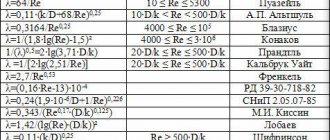
The value of the hydraulic resistance coefficient λ depends on the flow mode and the roughness of the pipeline wall material. Roughness refers to defects and unevenness of the inner surface of the pipe. It can be absolute and relative. The roughness varies in shape and is uneven across the surface area of the pipe. Therefore, the calculations use the concept of average roughness with a correction factor (k1). This characteristic for a particular pipeline depends on the material, the duration of its operation, the presence of various corrosion defects and other reasons. The values discussed above are for reference.
The quantitative relationship between the coefficient of friction, Reynolds number and roughness is determined by the Moody diagram.
To calculate the friction coefficient of turbulent flow motion, the Colebrook-White equation is also used, with the use of which it is possible to visually construct graphical dependencies by which the friction coefficient is determined:
The calculations also use other equations for approximate calculation of friction head loss. One of the most convenient and frequently used in this case is the Darcy-Weisbach formula. Friction pressure losses are considered as a function of fluid velocity from the pipe resistance to fluid movement, expressed through the value of the surface roughness of the pipe walls:
Pressure loss due to friction for water is calculated using the Hazen-Williams formula:
Program overview
For ease of calculations, amateur and professional hydraulic calculation programs are used.
The most popular is Excel.
You can use online calculation in Excel Online, CombiMix 1.0, or online hydraulic calculation calculator. The stationary program is selected taking into account the requirements of the project.
The main difficulty in working with such programs is ignorance of the basics of hydraulics. Some of them lack explanations of formulas, and do not consider the features of branching pipelines and calculating resistance in complex circuits.
Features of the programs:
- HERZ CO 3.5 – performs calculations using the specific linear pressure loss method.
- DanfossCO and OvertopCO - can count systems with natural circulation.
- “Flow” (Potok) - allows you to use a calculation method with a variable (sliding) temperature difference along the risers.
It is necessary to clarify the parameters for entering temperature data - in Kelvin/Celsius.
Pressure loss calculation
The operating pressure in the pipeline is the higher excess pressure at which the specified mode of the technological process is ensured. The minimum and maximum pressure values, as well as the physical and chemical properties of the working medium, are the determining parameters when calculating the distance between the pumps pumping the media and the production capacity.
Calculation of losses due to pressure drop in the pipeline is carried out according to the equation:
