The key to flawless and efficient ventilation operation is a competent calculation of the area of air ducts and fittings, on which the selection of both individual elements and equipment depends. The purpose of the calculation is to ensure the optimal frequency of air changes in rooms in accordance with their purpose.
In the article, we examined in detail each of the required stages of calculations: determining the cross-section and actual area of ducts, calculating air speed and selecting the parameters of shaped products. In addition, we outlined the main requirements for the size of ventilation ducts, and also gave an example of calculating air ducts for a private house.
What data is needed to calculate the performance characteristics of air ducts?
First of all, the main parameters of the structure are taken into account, such as the purpose of the building itself, the volume of premises, the number of permanent staff and visitors, features of the production process (for industrial buildings), etc.
The design of ventilation systems is carried out in accordance with the following regulatory documents:
- SP 60.13330.2016 (current edition of SNiP 41-01-2003);
- SP 7.13130.2013;
- GOST 12.1.005-88 and some others.
How to calculate the area of an air duct of various types of sections?
Calculating the quadrature of air ducts of different sections has its own characteristics, since their air flow will differ significantly even with the same parameters for the speed of movement of air masses and area. In addition, when calculating ventilation networks of large length and/or branching, humidity and air temperature are taken into account (if it exceeds +20°C). As well as the aerodynamic resistance of air ducts and fittings, depending on the shape and material of manufacture (different friction coefficients). Taking these parameters into account is expressed in the use of various correction factors in the calculation formulas.
Important information! The channel quadrature parameters and the speed of air flow are inversely proportional. That is, with a large cross-section of the air duct, a lower speed is sufficient to ensure the required volume of moved air.
The quadrature is calculated using two parameters taken from the standards (in fact, these parameters describe the air exchange rate):
- air flow – R (m³/hour);
- air flow speed – V (m/s).
The air duct area formula operates on air flow parameters taken from the standards:
S = R/k × V, where
K – coefficient equal to 3600.
There are alternative formulas that operate with other coefficients, for example:
S = R × 2.778/V.
When using large cross-section air ducts, the noise level of air flows and the energy costs for their movement are significantly reduced. However, the material consumption of such structures is much higher, which increases their initial cost.
Decorative round air duct on hanging holders
The cross-sectional shape has a significant impact on the efficiency of air flow movement. In rectangular ducts, the air flow receives more resistance. However, the rectangular shape is more convenient for installation, especially when there is a lack of space, and can be placed adjacent to the main building structures. Round air ducts have better aerodynamics, but do not always fit into the interior. And products with high aesthetic indicators have a much higher cost. Considering the above facts, it is recommended as an alternative to pay attention to oval air ducts, which combine ergonomics and efficiency.
Ventilation ducts in an enterprise
How to calculate the area of a round air duct?
To calculate the diameter of a round ventilation duct, the standard cross-sectional area is used:
The actual area is obtained from the formula:
How to calculate the area of a rectangular duct?
For rectangular boxes, the same formulas are used as for round ones. The length of the sides is calculated using the formula:
Dп – diagonal of a rectangle inscribed in a circle (actually the equivalent diameter of a circle);
a, b – sides.
The actual area is determined from the formula:
Designers also use tables to calculate basic parameters.
Table of main parameters of area and shape of sections
Calculation of the area of an oval duct
The diameters of an oval duct are calculated based on its area. The following formulas are used:
Diameter:
P – perimeter of the ovaloid circle,
The area of the oval duct is calculated by the formula:
a, b – large and small diameter of the oval, respectively.
Oval air channels combine the advantages of rectangular and round ones
Video description
This video details the equivalent duct diameter:
Review of other techniques
In the accompanying documentation or specialized regulatory literature you can find graphic nonograms. There are several axes on which a scale is indicated for pressure, speed, air exchange and the cross-section of the ventilation duct. Knowing the first indicators, you can compare them and, at the intersection, consider the desired option for the contour size. The value will be approximate, but it can be guided by taking into account the minimum noise level.
Engineers and designers use special programs to calculate the quadrature of the air duct. There are cumbersome tables that take into account the maximum number of nuances. They are related both to the type of kit selected for installing a ventilation system, and to the characteristics of the room being served or the facility as a whole.
Specialized program for engineering calculations of ventilation Source odstroy.ru
An alternative to specialized programs is an online calculator. This approach allows you to determine the required standard sizes of ventilation ducts and shaped products with approximate accuracy. But taking into account the standardized parameters of the offered assortment on trading platforms, such results can be applied to drawing up a project for the private sector.
Algorithm for calculating the cross-section of air ducts
Calculation of the cross-section of air ducts involves determining the size of the air ducts depending on the flow rate of the air passed through. It is performed in 4 stages:
- Conversion of air flow to m3/s
- Choosing air speed in the duct
- Determining the cross-sectional area of the duct
- Determining the diameter of a round or width and height of a rectangular duct.
At the first stage of air duct calculation, the air flow rate G, usually expressed in m3/hour, is converted to m3/s. To do this, you need to divide it by 3600:
- G [m3/s] = G [m3/hour] / 3600
At the second stage, you should set the speed of air movement in the duct. The speed should be specified, not calculated. That is, choose the air speed that seems optimal.
The high air velocity in the duct allows the use of small cross-section ducts. However, the air flow will be noisy, and the aerodynamic resistance of the air duct will greatly increase.
Low air speed in the air duct ensures quiet operation of the ventilation system and low aerodynamic resistance, but makes the air ducts very bulky.
For general ventilation systems, the optimal air speed in the air duct is considered to be 4 m/s. For large air ducts (600x600 mm or more), the air speed can be increased to 6 m/s. In smoke removal systems, air speed can reach or exceed 10 m/s.
So, at the second stage of calculating air ducts, the air speed v [m/s] is set.
At the third stage, the required cross-sectional area of the air duct is determined by dividing the air flow by its speed:
- S [m2] = G [m3/s] / v [m/s]
At the fourth , final stage, its diameter or the lengths of the sides of a rectangular section are selected for the resulting cross-sectional area of the air duct.
Selecting an air handling unit
To select an air handling unit, we will need the values of three parameters: overall performance, heater power and air network resistance. We have already calculated the performance and power of the heater. The network resistance can be found using the Calculator or, for manual calculation, taken equal to the typical value (see section Calculation of network resistance).
To select a suitable model, we need to select ventilation units whose maximum performance is slightly greater than the calculated value. After this, using the ventilation characteristic, we determine the system performance at a given network resistance. If the obtained value is slightly higher than the required performance of the ventilation system, then the selected model is suitable for us.
As an example, let’s check whether a ventilation unit with the ventilation characteristics shown in the figure is suitable for a cottage with an area of 200 m².
The estimated productivity is 450 m³/h. Let us take the network resistance to be 120 Pa. To determine the actual performance, we must draw a horizontal line from the value of 120 Pa, and then draw a vertical line down from the point of its intersection with the graph. The intersection point of this line with the “Performance” axis will give us the desired value - about 480 m³/h, which is slightly more than the calculated value. So this model suits us.
Note that many modern fans have flat ventilation characteristics. This means that possible errors in determining the network resistance have almost no effect on the actual performance of the ventilation system. If in our example we had made a mistake in determining the resistance of the air supply network by 50 Pa (that is, the actual network resistance would not have been 120, but 180 Pa), the system performance would have dropped by only 20 m³/h to 460 m³/h, which had no effect would be the result of our choice.
After choosing an air handling unit (or a fan, if a dial system is used), it may turn out that its actual performance is noticeably higher than the calculated one, and the previous model of the air handling unit is not suitable because its performance is not enough. In this case we have several options:
- Leave everything as is, but the actual ventilation performance will be higher than the calculated one. This will lead to increased energy consumption spent on heating the air during the cold season.
- “Strangle” the ventilation unit using balancing throttle valves, closing them until the air flow in each room drops to the calculated level. This will also lead to excessive energy consumption (although not as much as in the first option), since the fan will work with excess load, overcoming the increased network resistance.
- Do not turn on maximum speed. This will help if the ventilation unit has 5–8 fan speeds (or smooth speed control). However, most budget ventilation units have only 3-step speed control, which most likely will not allow you to accurately select the desired performance.
- Reduce the maximum productivity of the air handling unit exactly to a specified level. This is possible if the automatic ventilation unit allows you to adjust the maximum fan rotation speed.
Example of air duct calculation
As an example, let's calculate the cross-section of an air duct with an air flow of 1000 m3/hour:
- G = 1000/3600 = 0.28 m3/s
- v = 4 m/s
- S = 0.28 / 4 = 0.07 m2
- In the case of a round duct, its diameter would be D = root (4·S/ π) ≈ 0.3 m = 300 mm. The nearest standard duct diameter is 315 mm.
In the case of a rectangular duct, it is necessary to select A and B such that their product is approximately 0.07. It is recommended that A and B do not differ from each other by more than three times, that is, a 700x100 air duct is not the best option. Better options: 300x250, 350x200.
Differences between kitchen hood and ventilation
Ventilation in the house ensures natural air exchange and air circulation in all rooms. It is designed for a standard low level of air pollution and cannot fully clean the kitchen from smoke, steam and strong odors.
A hood with an air duct is an additional air cleaning system, usually of a forced type. It is productive and can remove large amounts of smoky and polluted air, as well as eliminate most strong kitchen odors.
That is, the hood is the second level of ventilation, which is guaranteed to provide the required sanitary conditions and clean air in your kitchen under any load.
Calculation of the area of air ducts and fittings
Straight duct section
Circular duct area
| Diameter Length d | 100125160200250280315355400450500560630710800900100011201250140016001800200022402500 | mm | |
| L | m |
| m2 |
Rectangular duct area
| Width Height Length a | 5010015020025030035040045050055060065070075080085090095010001100120013001400150016001700180019002000 | mm | |
| b | 5010015020025030035040045050055060065070075080085090095010001100120013001400150016001700180019002000 | mm | |
| L | m |
| m2 |
Branch
S
Circular outlet area
| |||||
| Square | |||||
| m2 |
| 5010015020025030035040045050055060065070075080085090095010001100120013001400150016001700180019002000 | mm | |
| b | 5010015020025030035040045050055060065070075080085090095010001100120013001400150016001700180019002000 | mm |
| α | 1530456090 | ° |
| m2 |
Transition
| Circular transition area | 100125160200250280315355400450500560630710800900100011201250140016001800200022402500 | mm |
| D2 | 100125160200250280315355400450500560630710800900100011201250140016001800200022402500 | mm |
| L | mm |
| 5010015020025030035040045050055060065070075080085090095010001100120013001400150016001700180019002000 | mm | |
| b | 5010015020025030035040045050055060065070075080085090095010001100120013001400150016001700180019002000 | mm |
| D | 100125160200250280315355400450500560630710800900100011201250140016001800200022402500 | mm |
| L | mm |
| Width Height Width Height Length A | 5010015020025030035040045050055060065070075080085090095010001100120013001400150016001700180019002000 | mm |
| B | 5010015020025030035040045050055060065070075080085090095010001100120013001400150016001700180019002000 | mm |
| a | 5010015020025030035040045050055060065070075080085090095010001100120013001400150016001700180019002000 | mm |
| b | 5010015020025030035040045050055060065070075080085090095010001100120013001400150016001700180019002000 | mm |
| L | mm |
| m2 |
Tee
| Circular tee area | 100125160200250280315355400450500560630710800900100011201250140016001800200022402500 | mm |
| L | mm | |
| D2 | 100125160200250280315355400450500560630710800900100011201250140016001800200022402500 | mm |
| l | mm |
| 100125160200250280315355400450500560630710800900100011201250140016001800200022402500 | mm | |
| L | mm | |
| a | 5010015020025030035040045050055060065070075080085090095010001100120013001400150016001700180019002000 | mm |
| b | 5010015020025030035040045050055060065070075080085090095010001100120013001400150016001700180019002000 | mm |
| l | mm |
| mm | ||
| b | 5010015020025030035040045050055060065070075080085090095010001100120013001400150016001700180019002000 | mm |
| L | mm | |
| d | 100125160200250280315355400450500560630710800900100011201250140016001800200022402500 | mm |
| l | mm |
| 5010015020025030035040045050055060065070075080085090095010001100120013001400150016001700180019002000 | mm | |
| B | 5010015020025030035040045050055060065070075080085090095010001100120013001400150016001700180019002000 | mm |
| L | mm | |
| a | 5010015020025030035040045050055060065070075080085090095010001100120013001400150016001700180019002000 | mm |
| b | 5010015020025030035040045050055060065070075080085090095010001100120013001400150016001700180019002000 | mm |
| l | mm |
Stub
| Round plug area | 100125160200250280315355400450500560630710800900100011201250140016001800200022402500 | mm |
| 5010015020025030035040045050055060065070075080085090095010001100120013001400150016001700180019002000 | mm | |
| b | 5010015020025030035040045050055060065070075080085090095010001100120013001400150016001700180019002000 | mm |
Rectangular duck
| Weft area with offset in 1st plane | 5010015020025030035040045050055060065070075080085090095010001100120013001400150016001700180019002000 | mm |
| b | 5010015020025030035040045050055060065070075080085090095010001100120013001400150016001700180019002000 | mm |
| l | mm | |
| h | mm |
| 5010015020025030035040045050055060065070075080085090095010001100120013001400150016001700180019002000 | mm | |
| b | 5010015020025030035040045050055060065070075080085090095010001100120013001400150016001700180019002000 | mm |
| l | mm | |
| h1 | mm | |
| h2 | mm |
Umbrellas
| Island type umbrella area | 5010015020025030035040045050055060065070075080085090095010001100120013001400150016001700180019002000 | mm |
| B | 5010015020025030035040045050055060065070075080085090095010001100120013001400150016001700180019002000 | mm |
| a | 5010015020025030035040045050055060065070075080085090095010001100120013001400150016001700180019002000 | mm |
| b | 5010015020025030035040045050055060065070075080085090095010001100120013001400150016001700180019002000 | mm |
| h | mm |
| 5010015020025030035040045050055060065070075080085090095010001100120013001400150016001700180019002000 | mm | |
| b | 5010015020025030035040045050055060065070075080085090095010001100120013001400150016001700180019002000 | mm |
| h | mm | |
| c | 5010015020025030035040045050055060065070075080085090095010001100120013001400150016001700180019002000 | mm |
Calculation of the area of duct fittings
It will be difficult for a person not familiar with mathematical formulas to perform calculations correctly; an error in one indicator will affect the operational characteristics of the ventilation system, and accordingly, the quality of air purification.
To simplify the process of calculating the surface area of the air duct, you can use an online calculator and special programs that perform all the algorithms; for this you only need to enter the primary indicators.
Program for counting and selecting elements
What programs exist for finding the parameters of duct fittings?
To help engineering workers eliminate errors associated with the human factor, as well as to speed up the process, special programs have been created, with the help of which you can not only perform competent calculations, but also 3D modeling of the future structure.
| Program | Short description |
| Vent-Calc | The program calculates the cross-sectional area, thrust, resistance on different segments. |
| GIDRV 3.093 | The program will perform a new and control calculation of the air duct data. |
| Ducter 2.5 | In the program you can select the elements of the ventilation system and calculate the cross-sectional areas of the structure. |
| CADvent | This complex is created on the basis of AutoCAD and has the most detailed library of elements and capabilities. |
Software calculation and design of ventilation
Calculation of square meters (sectional area) of the air duct
The size of the ventilation pipe is influenced by many factors: flow speed, pressure on the walls, air volume. If you make calculations with an error, for example, reduce the cross-section of the main network, the speed of air masses will increase, noise will appear, pressure and electricity consumption will increase.
The calculation of the cross-sectional area of the duct is calculated using the following formula:
S = L × κ / ω , where:
- L – air flow, m³/h;
- ω – speed of air flow, m/s;
- κ – calculated coefficient equal to 2.778.
Calculation of equivalent diameter of air ducts
The equivalent diameter of a rectangular duct is calculated by the formula:
- Deq_pr = 2 A B / (A + B), where A and B are the width and height of the rectangular air duct.
For example, the equivalent diameter of a 500×300 duct is 2·500·300 / (500+300) = 375 mm. This means that a 375mm round duct will have the same aerodynamic drag as a 500x300mm rectangular duct.
The equivalent diameter of a square duct is equal to the side of the square:
- Deq_q = 2 A A / (A+A) = A.
And this fact is very interesting, because usually the larger the cross-sectional area of the air duct, the lower its resistance. However, the round shape of the air duct section has the best aerodynamic performance. That is why the resistance of square and round ducts are equal, although the cross-sectional area of a square duct is 27% larger than the cross-sectional area of a round duct.
In general, the formula for the equivalent duct diameter is as follows:
- Deq = 4·S / P, where S and P are the area and perimeter of the air duct, respectively.
Using this formula, you can confirm the correctness of the above formulas for rectangular and square ducts, and also ensure that the equivalent diameter of a round duct is equal to the diameter of this duct:
- Dround = 4·π·R2 / 2·π·R = 2R = D.
In addition, a table of equivalent duct diameters
Factors influencing the size of air ducts
At facilities being designed or newly built, successfully laying pipelines for ventilation systems is not a big problem - it is enough to coordinate the location of the systems in relation to workplaces, equipment and other utility networks. In existing industrial buildings this is much more difficult to do due to limited space.
This and several other factors influence the calculation of the duct diameter:
1. One of the main factors is the flow rate of supply or exhaust air per unit of time (m 3 / h), which a given channel must pass. 2. Capacity also depends on air speed (m/s).
It cannot be too small, otherwise, according to the calculation, the size of the air duct will be very large, which is not economically feasible. Too high a speed can cause vibrations, increased noise levels and increased power of the ventilation unit. It is recommended to take different speeds for different sections of the supply system; its value ranges from 1.5 to 8 m/s.
3. The material of the air duct matters. This is usually galvanized steel, but other materials are also used: various types of plastics, stainless or black steel. The latter has the highest surface roughness, the flow resistance will be higher, and the channel size will have to be larger. The diameter value should be selected in accordance with the regulatory documentation.
Table 1 shows the normal dimensions of air ducts and the thickness of the metal for their manufacture.
Table 1
Note: Table 1 does not completely reflect the normal, but only the most common channel sizes.
Air ducts are produced not only in round, but also in rectangular and oval shapes.
Their dimensions are taken through the value of the equivalent diameter. Also, new methods for making channels make it possible to use thinner metal, while increasing the speed in them without the risk of causing vibration and noise. This applies to spiral-wound air ducts; they have high density and rigidity.
Calculation of materials for air ducts and fittings
Having the area of straight sections, the number and type of shaped products, we can easily determine the volume of material that will be used in their manufacture. For example, to manufacture a section of a circular duct with a diameter of 100 mm and a length of 1 m, 0.314 m² of sheet metal will be needed.
This can be easily calculated using the formula:
π × D (100 mm = 0.1 m) × L (1 m) = 3.14 × 0.1 × 1 = 0.314 m².
The amount of material for straight sections of rectangular air ducts is calculated in a similar way.
There are no specific formulas for calculating shaped products. More precisely, they exist: for each part of a shaped product of a certain shape there is a separate formula. But calculating them manually is impractical. As a rule, the required amount of material is calculated empirically after making cutting patterns.
The process of creating a circular air duct by winding a steel spiral tape
An example of calculating the equivalent diameter of air ducts and some conclusions
As an example, let's determine the equivalent diameter of the duct 600×300:
Deq_600_300 = 2 600 300 / (600+300) = 400 mm.
It is interesting to note that the cross-sectional area of a round duct with a diameter of 400 mm is 0.126 m2, and the cross-sectional area of a 600x300 duct is 0.18 m2, which is 42% more. The steel consumption per 1 meter of a round air duct with a cross-section of 400 mm is 1.25 m2, and for 1 meter of an air duct with a cross-section of 600×300 - 1.8 m2, which is 44% more.
Thus, any rectangular air duct similar to a round one is significantly inferior to it both in compactness and in metal consumption.
Let's consider another example - let's determine the equivalent diameter of the air duct 500×100 mm:
Deq_500_100 = 2·500·100 / (500+100) = 167 mm.
Here the difference in cross-sectional area and metal consumption reaches 2.5 times. Thus, the equivalent diameter formula for a rectangular duct explains the fact that the more “flattened” the duct is (the greater the difference between the values of A and B), the less efficient this duct is from an aerodynamic point of view.
This is one of the reasons why it is not recommended to use air ducts in ventilation technology, in the cross-section of which one side is more than three times larger than the other.
General information
Aerodynamic calculation is a technique for determining the cross-sectional dimensions of air ducts to level out pressure losses, maintain the speed of movement and the design volume of pumped air.
With the natural ventilation method, the required pressure is given initially, but the cross-section must be determined. This is due to the action of gravitational forces, which encourage air masses to be drawn into the room from the ventilation shafts. With the mechanical method, a fan operates, and it is necessary to calculate the gas pressure, as well as the cross-sectional area of the box. Maximum speeds inside the ventilation duct are used.
To simplify the technique, air masses are taken as a liquid with zero percent compression. In practice, this is true, since in most systems the pressure is minimal. It is formed only from local resistance, when it collides with the walls of the air ducts, as well as at places where the area changes. This was confirmed by numerous experiments conducted according to the methodology described in GOST 12.3.018-79 “System of Occupational Safety Standards (OSSS). Ventilation systems. Methods of aerodynamic tests".
The technique involves selecting the area and cross-sectional shape for each section of the ventilation system. If we take it as a whole, then the definition of losses will be conditional, not corresponding to the real picture. In addition to the movement itself, the injection is also calculated.
Calculations of air ducts for ventilation, based on aerodynamics, are carried out with a varying number of known data. In one case, the calculation starts from scratch, and in the other, more than half of the initial parameters are already known.
Calculation of heating power in the network
The temperature of the air entering the premises is strictly regulated. For example, for residential buildings the minimum value is +18°C. To calculate the power of the heating equipment used, it is necessary to find out from the standards the minimum temperature value of the climatic zone where the building is located. The difference between these temperatures is the main factor in determining the power of the heating device. At the same time, it is not at all necessary to use the most powerful heater capable of heating the room at a minimum external temperature. If the ventilation has a performance control system, then during maximum load on the heater the air supply intensity is simply reduced.
The power of the heating device is calculated using the formula:
P — design power of the heating device (recuperator or heater), (kW);
Δt — difference in air temperature at the entrance to the ventilation system and at the supply to the room, (°C);
Q — ventilation system performance, (m³/h);
τv is the volumetric heat capacity of air, depends on the totality of the values of humidity, temperature and pressure, but is taken as a coefficient of 0.336 W × (h/m³/°C).
Examples of using air ducts as a decorative element of premises
Rules for using measuring devices
When measuring air flow speed and its consumption in a ventilation and air conditioning system, you need to correctly select devices and comply with the following rules for their operation.
This will allow you to obtain accurate results of air duct calculations, as well as create an objective picture of the ventilation system.
Observe the temperature regime indicated in the device passport. Also monitor the position of the probe sensor. It must always be oriented exactly towards the air flow.
If this rule is not followed, the measurement results will be distorted. The greater the deviation of the sensor from the ideal position, the higher the error will be.
Calculation of air speed in the duct
When calculating a ventilation system, one of the main indicators is the air exchange rate. In other words, how much air mass is needed to comfortably ventilate 1 m³ of a room in 1 hour. In this case, you can also refer to the development tables, but you should know that all the indicators in them are rounded, so more accurate data is obtained by doing your own calculations. The air exchange rate can be calculated using the formula:
N = V / W , where
- V – the amount of fresh air masses that enter the room in 60 minutes (m³/hour);
- W – room volume, m³.
You should know this! A comfortable air exchange rate for most domestic ventilation systems is 3-4 m/s.
You can carry out aerodynamic calculations and calculate the speed of air movement using the following formula:
ω = L / 3600 × S , where
- L – volume of air used per 1 hour;
- S – cross-sectional area of the air duct.
Air exchange standards for an apartment
Sanitary requirements of regulatory documents
The minimum amount of air supplied and removed from the rooms of the cottage by the ventilation system is regulated by two main documents:
- “Residential multi-apartment buildings” - SNiP 31-01-2003, paragraph 9.
- “Heating, ventilation and air conditioning” - SP 60.13330.2012, mandatory Appendix “K”.
We recommend: Optimal bed size: what should be the width of the aisles
The first document sets out sanitary and hygienic requirements for air exchange in residential premises of apartment buildings. There are 2 types of dimensions used - air mass flow rate by volume per unit of time (m³/h) and hourly multiplicity.
Reference. The air exchange rate is expressed by a number indicating how many times within 1 hour the air environment of the room is completely renewed.
Ventilation is a primitive way to renew oxygen in a home
Depending on the purpose of the room, supply and exhaust ventilation should provide the following flow rate or number of air mixture updates (multiplicity):
- living room, children's room, bedroom - 1 time per hour;
- kitchen with electric stove – 60 m³/h;
- bathroom, bathtub, toilet – 25 m³/h;
- for a furnace with a solid fuel boiler and a kitchen with a gas stove, a multiplicity of 1 plus 100 m³/h is required during the operation of the equipment;
- burning natural gas - three times renewal plus the volume of air required for combustion;
- pantry, dressing room and other utility rooms - multiplicity 0.2;
- drying or washing room – 90 m³/h;
- library, study – 0.5 times per hour.
Note. SNiP provides for reducing the load on general ventilation when equipment is not working or people are absent. In residential premises, the multiplicity is reduced to 0.2, in technical premises - to 0.5. The requirement for rooms where gas-using installations are located remains unchanged - an hourly one-time update of the air environment.
The release of harmful gases due to natural draft is the cheapest and easiest way to renew the air
Clause 9 of the document implies that the exhaust volume is equal to the inflow volume. The requirements of SP 60.13330.2012 are somewhat simpler and depend on the number of people staying in the room for 2 hours or more:
- If 1 resident has 20 m² or more of apartment area, the rooms are provided with a fresh influx of 30 m³/h per 1 person.
- The volume of supply air is calculated by area when there are less than 20 square meters per resident. The ratio is as follows: 3 m³ of inflow is supplied per 1 m² of housing.
- If ventilation is not provided in the apartment (there are no vents or opening windows), 60 m³/h of clean mixture must be supplied to each resident, regardless of the square footage.
The listed regulatory requirements of two different documents do not contradict each other at all. Initially, the performance of the general ventilation system is calculated according to SNiP 31-01-2003 “Residential buildings”.
The results are checked against the requirements of the Code of Practice “Ventilation and Air Conditioning” and, if necessary, adjusted. Below we will analyze the calculation algorithm using the example of a one-story house shown in the drawing.
Pressure loss at local resistances
In the air duct network there are places of greatest resistance to air flow: turns, bends, tees, places where the cross-section changes on adapters. Their aerodynamic losses are calculated separately, since each type of shaped product has individual drag coefficients.
Table of local resistance coefficients (KMR) for various shaped products
Formula for pressure loss at each section of local resistance, taking into account the coefficients:
where S is speed, ρ is air density.
Important! The density of air depends on its temperature. For example, at 20°C the air density will be 1.2 kg/m³. This parameter is also taken from tables in relevant regulatory sources.
General formula for pressure loss in shaped products:
Σξ – sum of local resistance parameters.
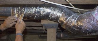
Sound and heat insulation of ventilation ducts
ENGINEERING ASSISTANCE
where: Qt – heater heat power, W; ρair – air density. The density of dry air at 15°C at sea level is 1.225 kg/m³; svozd. – specific heat capacity of air equal to 1 kJ/(kg∙K)=0.24 kcal/(kg∙°C); tvn. – air temperature at the outlet of the heater, °C; tnar. – outside air temperature, °C (air temperature of the coldest five-day period with a probability of 0.92 according to Construction Climatology).
Coolant consumption per heater
G= (3.6∙Qt)/(st∙(tpr-tbr) ),
where: 3.6 is the conversion factor of W to kJ/h (to obtain the flow rate in kg/h); G—water consumption for heating the air heater, kg/h;
Qt – heater heat power, W;
sv – specific heat capacity of water equal to 4.187 kJ/(kg∙K)=1 kcal/(kg∙°С); tpr. – coolant temperature (straight line), °C; tnar. – coolant temperature (return line), °C.
Selecting the diameter of pipes for heating the heater
Water consumption per heater, kg/h
| Coolant velocity in the pipe | |||||||||||
| Ø, mm | DN 10 | DN 15 | DN 20 | DN 25 | DN 32 | DN 40 | DN 50 | DN 70 | DN 80 | DN 90 | DN 100 |
| v , m/s |
The process of heating the air in the heater occurs at d=const (with constant moisture content).
The process of heating air in a heater from -28°C to +20°C.
helpeng.ru
Formula for calculating the area of air ducts
The area of the air ducts is determined by multiplying the perimeter of the air duct cross-section by the length of the air duct:
- S = П·L, where П and L are, respectively, the perimeter and length of the air duct in meters.
It is important to remember the dimensions of the quantities in the formula above. Typically, the duct cross-section is specified in millimeters (for example, diameter 250 or section 500×250), and the length is specified in meters (for example, 5 meters). But it is necessary to substitute all values expressed in meters into the formula. Moreover, you must first calculate the length of the perimeter of the air duct section.
To simplify the task of calculating the area of air ducts, ready-made formulas for round and rectangular air ducts are used.
Recommended air speed values in the ventilation system, m/s
| Apartments | Offices | Industrial premises | |
| Supply grilles | 2.0-2.5 | 2.0-2.5 | 2.5-6.0 |
| Main air ducts | 3.5-5.0 | 3.5-6.0 | 6.0-11.0 |
| Branches | 3.0-5.0 | 3.0-6.5 | 4.0-9.0 |
| Air filters | 1.2-1.5 | 1.5-1.8 | 1.5-1.8 |
| Heat exchangers | 2.2-2.5 | 2.5-3.0 | 2.5-3.0 |