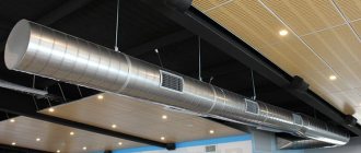
We all clearly saw in the aerodynamic calculation table the column of the local drag coefficient (LDC). Let's try to find answers to the questions: What is this? What factors does the local resistance coefficient depend on? Why take it into account at all? And the most important question: how to determine the coefficients of local resistance of air ducts ? The value is determined experimentally and by calculations. For standard elements such as tee, elbow, valve, diffuser, grilles and others, local resistance coefficients have long been determined. Data with the coefficient values can be found in reference literature, or they are indicated in the manufacturer’s catalog. There are times when you need to use a calculator. Below you can see tables of coefficients from reference books and catalogues, and we will also consider the calculation of the coefficient of local resistance and what it depends on.
Local resistance coefficient
First, let's define the local resistance coefficient. Local resistances are called point pressure losses associated with changes in the flow structure. There are many components in ventilation that play the role of local resistance:
- air duct rotation,
- narrowing or widening of the flow,
- air entry into the air intake shaft;
- “tee” and “cross”;
- supply and exhaust grilles and air distributors;
- air distributors;
- diffuser;
- dampers, etc.
Their KMS are calculated using certain formulas, and then they participate in determining local pressure losses. In mathematical terms, the local loss coefficient is the ratio of the loss of a known pressure in local resistance to the velocity pressure.
The coefficient of local resistance depends on the shape and type of local resistance, the roughness of the air duct and, oddly enough, on the Reynolds number. For dampers and other shut-off valves, the opening degree is added to the above.
The relationship between the CMR and the Reynolds number is expressed in the formula
Values of coefficients B
for some local resistances
The larger the Re number, the less the coefficient depends on it. Complete independence of the local resistance coefficient from the number Re in the ventilation system occurs for sharp transitions at Re > 3000, and for smooth transitions - at Re > 10000.
The total coefficient of local resistance in a section of the air duct is equal to the sum of all local coefficients in this section.
In practice, there is no special time for calculating the CMC, so designers use tables from reference books and other sources. Moreover, why waste a lot of time searching for formulas and calculations if it has already been done for you. Many ]silencers[/anchor], valves and grilles are happy to indicate the value of the local resistance coefficient in catalogs. But, of course, if you haven’t found any data at all, then you need to resort to mathematics.
see also
- Do-it-yourself ventilation on the balcony
- Crankcase ventilation valve accent tagaz
- Cleaning the ventilation system
- Plastic pipes for ventilation dimensions
- Ventilation in the waiting room
- How to properly ventilate a chicken coop
- Ventilation in a timber bath
- Supply ventilation valve KPV 125
- Industrial premises ventilation project
- Aluminum profile for ventilation
- Do-it-yourself ventilation in the steam room diagram
Table of local resistance coefficients
We have analyzed technical literature and other sources and provide you with tables with CMR values for different elements of the system for your use. In our case, these are catalogs from VEZA, Belimo, a reference book by the designer N, N, Pavlov and a reference book by R.V. Shchekin.
Resistance coefficient value for elbow, elbow, expansion, contraction, diffuser and confuser
Table of tee local resistance coefficients
Table of local resistance coefficients of valves, gates, umbrellas, grilles
Local resistance coefficient of the check valve depending on the dimensions
Table of KMS values for flow openings
Fire damper local resistance coefficient value
We hope the article will be useful to you.
Permissible speed method
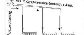
When calculating the air duct network using the permissible speed method, the optimal air speed is taken as the initial data (see table). Then the required cross-section of the air duct and the pressure loss in it are calculated.
Procedure for aerodynamic calculation of air ducts using the permissible speed method:
- Draw a diagram of the air distribution system. For each section of the air duct, indicate the length and amount of air passing in 1 hour.
- We start the calculation from the areas farthest from the fan and the most loaded.
- Knowing the optimal air speed for a given room and the volume of air passing through the air duct in 1 hour, we will determine the appropriate diameter (or cross-section) of the air duct.
- We calculate the pressure loss due to friction P tr.
- Using the tabular data, we determine the sum of local resistances Q and calculate the pressure loss due to local resistances z.
- The available pressure for the following branches of the air distribution network is determined as the sum of pressure losses in the areas located before this branch.
During the calculation process, it is necessary to sequentially link all branches of the network, equating the resistance of each branch to the resistance of the most loaded branch. This is done using diaphragms. They are installed on lightly loaded areas of air ducts, increasing resistance.
Table of maximum air speed depending on duct requirements
Min. head loss
Note: air flow speed in the table is given in meters per second
Constant head loss method
This method assumes a constant loss of pressure per 1 linear meter of air duct. Based on this, the dimensions of the air duct network are determined. The method of constant pressure loss is quite simple and is used at the stage of feasibility study of ventilation systems:
- Depending on the purpose of the room, according to the table of permissible air speeds, select the speed on the main section of the air duct.
- Based on the speed determined in paragraph 1 and based on the design air flow, the initial pressure loss is found (per 1 m of duct length). The diagram below does this.
- The most loaded branch is determined, and its length is taken as the equivalent length of the air distribution system. Most often this is the distance to the farthest diffuser.
- Multiply the equivalent length of the system by the pressure loss from step 2. The pressure loss at the diffusers is added to the resulting value.
Now, using the diagram below, determine the diameter of the initial air duct coming from the fan, and then the diameters of the remaining sections of the network according to the corresponding air flow rates. In this case, the initial pressure loss is assumed to be constant.
Diagram for determining pressure loss and diameter of air ducts
Using rectangular ducts
The pressure loss diagram shows the diameters of round ducts. If rectangular ducts are used instead, their equivalent diameters must be found using the table below.
- If space allows, it is better to choose round or square air ducts;
- If there is not enough space (for example, during reconstruction), rectangular air ducts are chosen. As a rule, the width of the duct is 2 times the height).
The table shows the height of the air duct in mm along the horizontal line, its width along the vertical line, and the cells of the table contain the equivalent diameters of the air ducts in mm.
Table of equivalent duct diameters
AERODYNAMIC CALCULATION OF VENTILATION SYSTEMS
6.1. Aerodynamic calculation of supply ventilation systems.
Aerodynamic calculations are carried out to determine the cross-sectional dimensions of air ducts and channels of supply and exhaust ventilation systems and determine the pressure that ensures the calculated air flow rates in all sections of the air ducts.
Aerodynamic calculation consists of two stages:
1. Calculation of sections of air ducts in the main direction - the main line;
2. Linking branches.
Aerodynamic calculations are performed in the following sequence:
1) The system is divided into separate sections. The lengths of all sections and the costs for them are included in the calculation diagram.
2) The main highway is selected. The branch of maximum length and maximum load is selected as the main highway.
3) We number the sections, starting with the most remote section of the highway.
4) Determine the dimensions of the sections of the design sections using the formula:
The cross-sectional dimensions of air ducts are selected based on optimal air speeds. The maximum permissible speeds for the supply mechanical ventilation system are taken according to Table 3.5.1 of the source [1]:
— for a highway 8 m/s;
— for branches 5 m/s.
5) The dimensions of the air duct are selected based on the calculated area f.
Then the speed is specified using the formula:
6) Determine pressure loss due to friction:
where R is the specific pressure loss due to friction, Pa/m.
Accepted according to the table. 22.15 of the Designer's Handbook (input by equivalent diameter de and air velocity v).
l is the length of the section, m.
Vsh is a coefficient that takes into account the roughness of the internal surface of the air duct channel (for steel Vsh = 1, for channels in brick walls Vsh = 1.36). Accepted according to the table. 22.12 Designer's Handbook.
7) We determine the pressure loss in local resistances using the formula:
where ∑ζ is the sum of the local resistance coefficients of the section, taken according to the Designer's Handbook;
pD — dynamic pressure, Pa.
 Determine the total pressure loss in the design area
9) Determine the pressure loss in the system using the formula:
where N is the number of sections of the highway.
p - pressure loss in ventilation equipment.
10) We link the branches, starting with the longest branch. The pressure loss in the branch is equal to the pressure loss in the main from the peripheral section to the common point with the branch:
The mismatch of pressure losses along air duct branches should not exceed 10% of the pressure losses on parallel sections of the main line. If during the calculation process it turns out that by changing the diameter it is impossible to equalize the losses, then we install diaphragms, throttle valves or equalize them with grilles (adjustable grilles of type P and PP).
Aerodynamic calculations of the system P1, P2, P3, P4, V1, V2, V3, V4, V5, V6, V7, V8 are summarized in tables No. 6-16. After calculations, sections of air ducts are plotted on the diagrams indicating the flow rates.
6.2. Aerodynamic calculation of ventilation systems with natural impulse of air movement.
When calculating a natural ventilation system, it is necessary that the losses in the system be less than the pressure created by the density difference (available pressure).
When calculating, we try to maintain a discrepancy of 5-10% between the pressure loss in the system and the available pressure, but if it is necessary to increase the losses in the system, we use adjustable grids.
The available pressure is calculated using the formula:
where ρн, ρв - air densities at tн and tв respectively (calculation is carried out at outside air temperature tн = 5 о C);
h is the height of the air column, m.
The height of the air column depends on the presence or absence of a supply ventilation system in a given room:
— if the room has a supply ventilation system, then the height of the air column is equal to the distance from the middle of the height of the room to the mouth of the exhaust shaft;
— if there is only an exhaust system in the room, then the height of the air column is equal to the distance from the middle of the exhaust hole
to the mouth of the exhaust shaft.
The calculation of a ventilation system with natural impulse is carried out in the following order:
1) Determine the highway. For natural exhaust, this will be the branch for which the available pressure will be the least.
2) Determination of the cross-section of the channels is carried out similarly to the supply mechanical system.
3) We calculate the remaining branches in the same way as the main line, comparing the residual with the available pressure.
7. SELECTION OF VENTILATION EQUIPMENT
7.1. Selection of fixed louver grilles.
The role of the air intake device is performed by louvered grilles of the STD type. They are mounted in a hole in the wall of the ventilation chamber. This design solution of the air intake device does not contradict sanitary and hygienic requirements, since there are no external air pollutants near it. Air intake is carried out in accordance with the requirements according to which air intake devices should not be lower than 2 m from ground level.
The selection is made in the following order:
1) for a given air flow, select one or more grilles with a total open cross-section
where v is the recommended speed of air movement in the grille section. Taken equal to 2 - 6 m/s;
Ltot - volumetric flow rate of air passing through the grille, m 3 /h.
f = 13386 / (3600 4) = 0.93 m2
The number of gratings is defined as
where f1 is the open cross-sectional area of one grating, m2.
n = 0.93 / 0.183 =5 pcs.
a grating type STD 302 with a clear cross-sectional area f1 = 0.183 m 2 was adopted
2) We clarify the speed using the formula
where ffact is the actual total cross-sectional area, m2.
v = 13386 / (3600 0.915) = 4 m/s
3) We calculate the pressure loss in the grids using the formula:
p= ζ (ρ v 2 ) / 2,
where ζ is the local resistance coefficient. For STD type gratings it is equal to 1.2.
ρ is the density of outside air during the cold season at a temperature of -32 0 C, ρ = 1.48319 kg/m.
∆p = 1.2 · (1.48319 · 4 2 ) / 2 = 14.2 Pa.
Selection of fixed louver grille. Table 17