In this article, we will look at a step-by-step sequence of how to do this correctly, when and what tests should be carried out, and what mistakes may lie in wait for you in this matter. We will also touch upon the issue of automatic temperature control in rooms.
Secrets of saving heat
Now it has become known that using an elevator can save heat.
To do this, it is necessary to reduce the temperature in the apartment at night, or during the day, when most of the residents are absent. The disadvantage of such savings is the need to subsequently increase heat consumption to heat an already cooled room. But you sleep much better in a cool room, scientists say. To make savings effective, they began to develop an elevator with an adjustable nozzle. It is also water-jet like its predecessor. It differs not so much in design changes as in the depth of possible adjustment, without losing the high quality of its work.
But technology continues to develop and soon analogues of conventional elevator units will appear, which can be produced fully automatically.
Types of heating elevators
Oddly enough, not even all plumbers servicing multi-story buildings know about heating elevators. At best, they have an idea that this device is installed in the system. But how it works and what function it performs is not known to everyone, not to mention ordinary people.
Therefore, let's eliminate this gap in knowledge about heating systems and examine this device in more detail.
What is a mixing unit
The boiler usually heats water to 80-95°C, this is the optimal temperature for use in radiators. However, according to sanitary standards, the floor temperature should not be more than 30°C.
Exceeding this temperature can lead to an increased release of harmful substances from floor coverings, and in general it will be uncomfortable to walk on such a floor (see article on the dangers of heated floors and laminate).
Considering the thickness of the floor screed and floor covering, the temperature of the coolant in the circuits is not higher than 55°C. That is why water for heated floors is supplied through a mixing unit; it mixes hot liquid with cooler liquid (which has already passed through the system and has had time to cool). The system operation diagram is shown in the video:
System elements
When the hot coolant reaches the collector, it rests against the safety valve. The thermal head detects the temperature of the liquid and if it exceeds the set values, the valve opens slightly and the cold and hot coolant are mixed.
In addition, if the circuits are long, they often make a pumping and mixing unit with their own hands. It is equipped with a circular pump that circulates water through itself and increases the pressure in the system.
In addition to the main elements (two- or three-way valve and pump), the unit also contains additional parts: bypass (jumper), drain and shut-off valves, air vent, expansion tank.
How to install?
Before installing a water distribution unit for cold and hot water supply, give an accurate answer to the following questions and consider the following points:
- How many water consumers are there on site? The number of collector outlets should be the same or slightly greater than the number of consumers. Excess branches are closed with plugs.
- What type of pipes will be used to install the water supply? It is necessary to purchase devices designed specifically for pipes made of the selected material.
- Estimate in advance the position of all engineering elements in the space of the plumbing cabinet (you can make markings on the wall). Please note that a water meter and a water filter are installed in front of the distribution comb. The convenient location of all devices facilitates maintenance and repair work.
- Get reliable fastening - a poorly secured distribution unit can lead to depressurization of connections and damage to the pipeline.
- Before installation, make sure that you have all the necessary consumables on hand: sealing material, gaskets, adapters.
Installation of the water distribution unit occurs in the following sequence:
- Install the inlet shut-off valves on the water supply riser.
- Install the meter, filter and check valve.
- Connect the manifold and securely fix it to the wall
- Install a water supply to each consumer. Secure the pipes with fasteners.
This operating algorithm will allow you to avoid errors. Regardless of whether the collector is needed for water supply or heating, its installation is the same. Such wiring requires more time, skill and money, but pays off quickly and provides comfort in further use. Collectors are appropriate not only in cottages and large houses, but also in apartments.
How to tighten fittings for a metal-plastic pipe on a heated floor manifold
How tightly and with what can you tighten the fittings for metal-plastic pipes on the underfloor heating manifold?
I work with metal-plastic with this key,
The “sponges” are thinner and can be spread out easily and quickly to suit any number.
In general, the nut on the fitting depends on the diameter of the pipes.
Most often, for heated floors, a metal-plastic pipe is used, 16 mm, less often 20 mm.
The keys, if we talk about open-end ones, are on the 24th, 27th.
Is the manifold also for metal-plastic pipes?
If the pipes are connected, for example, to a polypropylene manifold,
Again, there are subtleties, do we go through “father” or through “mother”?
You need to know this in order to advise which key is more convenient to work with.
In general, buy the universal one I mentioned above (preferably two), suitable for any pipes, with any fittings.
This key is even convenient for holding the polypropylene manifold on which the metal-plastic fitting will be mounted.
www.remotvet.ru
Types of collectors
The design of the collectors is simple, so it makes sense to differentiate only by the material from which the combs are made and by the method of attaching the pipes. Structurally, they are divided into two groups:
- Distribution manifold. Designed to distribute liquid from a common channel to end consumers, distributing water into separate channels.
- Collection (return) manifold. Designed to receive liquid from several channels and send it to a common channel of the system.
Conventionally, collectors are divided according to the number of branches, the presence of shut-off valves, and the sizes of inlet and outlet openings.
These factors will have to be taken into account when choosing. A large number of circuits may require several collectors.
Mounting types
According to the type of fastening of elements, they are distinguished:
- With solder fittings. This method is often used for polypropylene pipes, less often for cross-linked polyethylene.
- Euroconus. Suitable for all types of pipes and manifolds.
- Combined. For example, the inlet hole is threaded, and the outlet holes are made for soldering with polypropylene pipes.
Types of collectors and ease of installation
The most convenient to install combs are made of cross-linked polyethylene. The collector material that is slightly less easy to install is polypropylene.
Installation of a polypropylene manifold and pipes can be done using fittings or welding - this is an effective and reliable method of creating joints, but makes it difficult to change certain sections of the structure. If the pipe is directly welded to the comb, then in the event of a leak at the junction with the manifold, the entire structure will need to be replaced, so it is better to use fittings to connect to the comb.
We recommend that you read: What is the maximum temperature that a polypropylene pipeline can withstand?
The tensile strength of polypropylene is high both in elongation and bending. When heated, you can deform the material and make bends, but you need to be careful here. When heated, the strength of the material decreases, which increases the likelihood of damage.
Composition of a collector heating system
A simple collector heating scheme
At the first stage, it is necessary to become familiar with the design principle of autonomous heat supply. The simplest collector heating scheme consists of one distribution unit, to which individual lines of the system are connected.
The composition includes standard components - a boiler, a circulation pump, an expansion tank and a safety group. The collector unit is installed directly next to the boiler and consists of two elements:
- Input. It is connected to the supply pipe from the heating device and distributes the hot coolant along the circuits;
- Day off. Return pipes from individual mains lead to it. Necessary for collecting cooled water and sending it to the boiler for further heating.
Complex manifold groups for heating are equipped with devices for regulating the volume of coolant supply - thermal heads (input) and mechanical limiters at the outlet.
It is best to purchase factory-made manifolds. Since they are designed for certain heating parameters.
Multi-level collector heating
This principle is used to organize heat supply to a one-story private house, where the power of the circulation pump will be sufficient to ensure normal pressure in the pipes. For a two-story building, two collector groups for heating can be installed. One of them will be intended for distribution over individual circuits, and the second will serve as the main component of a warm water floor.
For such a scheme, it is necessary to calculate the parameters of each circuit. Most often there is a need to install the following additional components:
- Circulation pumps for each circuit;
- Mixing unit. Necessary for regulating the temperature of the coolant in the collector. The channel connects the forward and return pipes, and with the help of a control device (two or three-way valve), flows with varying degrees of heating are mixed.
Collector diagram of a two-story house
The traditional collector heating scheme for a two-story house includes distribution units on the first and second levels. But everything depends on the total area of the premises and, as a consequence, on the length of individual highways.
You also need to take into account heat transfer and optimal thermal conditions in each room.
All collectors located in residential premises must be installed in special closed boxes.
“Hot” joining method: welding options
When using this method, 2 welding options are used:
- Soldering pipe to pipe is the most popular method.
- Fusion welding of couplings (adapters).
The first method is used when welding pipes with a diameter of more than 40 mm. The second is on pipes with a diameter from 16 to 40 mm. In this case, the fitting is needed not only to adjust the direction of pipe laying, but also as a supply of material for melting.
Various configurations of couplings (adapters) Source education-web.ru
Coupling configurations are selected based on the characteristics of the pipeline. The following types of adapters are available:
- Corners . Change of direction in any direction.
- Tees . Distribution of water supply and change of direction.
- Couplings . Docking without changing direction.
The following elements also apply:
- Bypass fittings.
- Ball valves.
- Combined products including metal-plastic.
- Threaded inside or outside pipes.
What is it needed for
When installing water pressure systems, there is a rule: the total diameter of all branches should not exceed the diameter of the supply pipe. In relation to heating equipment, this rule looks like this: if the diameter of the boiler outlet fitting is 1 inch, then the system allows two circuits with a pipe diameter of ½ inch. For a small house heated only with radiators, such a system will work effectively.
In fact, there are more heating circuits in a private house or cottage: heated floors. heating of several floors, utility rooms, garage. When they are connected through a tapping system, the pressure in each circuit will be insufficient to effectively heat the radiators, and the temperature in the house will not be comfortable.
Therefore, branched heating systems are made using collector systems; this technique allows you to adjust each circuit separately and set the desired temperature in each room. So, for a garage, plus 10-15ºС is enough, and for a nursery, a temperature of about plus 23-25ºС is required. In addition, heated floors should not heat up more than 35-37 degrees, otherwise it will be unpleasant to walk on them, and the floor covering may become deformed. With the help of a manifold and shut-off temperature, this problem can also be solved.
Video: using a collector system for heating a house.
Manifold groups for heating systems are sold ready-made, and they can have different configurations and the number of outlets. You can select a suitable collector assembly and install it yourself or with the help of specialists.
However, most industrial models are universal and do not always fit the needs of a particular home. Redesigning or modifying them can significantly increase costs. Therefore, in most cases it is easier to assemble it from separate blocks with your own hands, taking into account the characteristics of a particular heating system.
Manifold group for heating system assembly
The design of the universal collector group is shown in the figure. It consists of two blocks for forward and reverse coolant flow, equipped with the required number of outlets. Flow meters are installed on the supply (direct) manifold, and thermal heads are located on the return manifold to regulate the return water temperature in each circuit. With their help, you can set the required coolant flow rate, which will determine the temperature in the heating radiators.
The manifold distribution unit is equipped with a pressure gauge, circulation pump and air valves. The supply and return manifolds are combined into one unit with brackets, which also serve to attach the unit to a wall or cabinet. The price of such a block is from 15 to 20 thousand rubles. and if some of the taps are not used, its installation will be clearly impractical.
The rules for installing the finished block are shown in the video.
Comb - collector unit
The most expensive elements in a manifold distribution block are flow meters and thermal heads. To avoid overpaying for unnecessary elements, you can buy a collector unit, the so-called “comb”, and install the necessary control devices with your own hands only where necessary.
The comb consists of brass tubes with a diameter of 1 or ¾ inches with a certain number of taps with a diameter of ½ inch for heating pipes. They are also connected to each other by a bracket. The outlets on the return manifold are equipped with plugs that allow you to install thermal heads on all or part of the circuits.
Some models may be equipped with taps, with their help you can regulate the flow manually. Such combs have a cast body and are equipped with a fitting/nut thread at the ends, which allows you to quickly and easily assemble a manifold from the required number of branches.
In order to save money, the manifold for heating systems can be assembled from individual elements independently or completely made by hand.
Manifold cabinet for underfloor heating: distribution, vacuum, with hydraulic arrow
Energy-efficient operation of heat supply systems is impossible without including a heating collector in the circuit, which is responsible for the proportional contour distribution of heat flows and the return of cold coolant to the boiler using a circulation pump. This made it possible to replace the linear circuit of powering consumers with an autonomous one, which increases the operational and repair readiness of the network.
Read in the article
What is a heating collector
The device is structurally made in the form of a metal comb, equipped with several “input-output” points, which autonomously connect heating batteries to the in-house coolant.
The purpose of this connection is to adjust and control heating parameters:
- volume of network water;
- network temperatures;
- pressure in the supply and return networks.
The design of the heating unit controls heat transfer and ensures sanitary and hygienic living standards in the premises.
Important! To install heating in two-story buildings, the unit is mounted on each floor, thus implementing a high-quality heat supply scheme with floor-by-floor regulation.
Operating principle of the heating manifold
The distributor has a simple operating principle, which consists of several stages:
- Water, heated in the boiler unit to operating temperature, enters the supply part of the manifold, where the speed of the medium slows down due to the increased diameter of the comb, so the liquid flows evenly through all branches, with the same pressure at the branch points, supported by valves or shut-off and control valves.
- Each node is connected to a supply pipe circuit, creating equal heating opportunities for the radiators in the system, which is especially important at low outside temperatures.
- The coolant through the batteries gives off heat to the internal air in the room and, when cooled, enters a separate lower part of the heating manifold, where it is collected from the return circuits.
- The circulation pump directs the cooled liquid into the boiler for the next heating-cooling cycle.
Note! The number of outlet pipes in a group of collectors varies, and the device can also be equipped with additional branches.
Main types of heating collectors
Combs differ from each other in three respects:
- placement location - wall-mounted or floor-mounted;
- number of heating circuits;
- control elements: valves, valves, pumps, sensors.
The Russian market presents various types of nodes:
- for water coolant of a multi-storey building;
- distribution boiler system;
- for solar systems;
- for 2/3/4 contour units;
- vacuum geocollector;
- knot with hydraulic arrow.
Distribution radiator type is used for conventional radiators. It is made of 2 interconnected parts for supply and return. Connection diagrams for the distribution manifold for heating depend on the design features of the heated objects. There are wiring diagrams:
- top type;
- bottom type;
- side;
- diagonal.
The lower one is the most popular, since with such a harness the system is hidden under the floor, so it does not interfere with users.
Note! In addition, calculations show the high energy efficiency of such a connection due to reduced losses.
An example of a manifold connection scheme is a water heated floor, where the distribution unit uniformly supplies the coolant to all network rings. Such heating systems are equipped with a circulation pump; the number of groups is selected from the ratio - 1 point per 120 m of pipeline.
The vacuum type belongs to classic solar systems and operates on the principle of a conventional water heater. There are two types of devices that differ in the organization of heating and storage of coolant:
- “Wet tube” - a tank for collecting hot water is combined with a comb.
- U-type - the container does not have a direct connection to the distribution unit, so it is not limited by size.
Operating principle of the vacuum device:
- Under the influence of direct sunlight, the process of thermal absorption and heat transfer to the copper core occurs.
- The water, heating up, rises to the top of the device.
- The hot coolant, having transferred its energy to the external circuit, cools and returns to the copper tube.
A collector heating system with a hydraulic arrow is used in the design of residential buildings with a large heated area on several levels. It is made in the form of a vertical hollow pipe, with elliptical-shaped plugs to equalize the coolant pressure. This design solves several problems simultaneously, the main one of which is the stabilization of sudden temperature changes in pipes, which increases the service life of the system.
Note! Optimal heating operation with a hydraulic arrow is ensured if each circuit is equipped with an independent circulation pump.
Solar type for solar systems using the greenhouse effect. Water circulation occurs due to convection. To absorb sunlight, a distributor is installed in the circuit. To accumulate heat, it is made in the form of a flat box treated with black adsorbent coating. Heat energy is transferred to the network fluid circulating through the pipes, which is used as water or antifreeze.
The water collector has a very wide application, both in cold and hot water supply systems, and for heating apartments. The upper part of the unit for the water supply network is equipped with flow meters that balance the heating circuits.
The lower one for the return line is equipped with valve taps that perform additional fine-tuning of the system used during repair work. For 4-circuit systems, the device is equipped with a mixing unit, adjusting ball valves, a Mayevsky valve and a drain valve.
2/3/4 circuit units are most popular for connecting 2, 3 and 4 heating circuits, which is sufficient for small private houses.
Collectors characteristics:
- Brass distribution device with internal thread.
- Areas of application: hot water supply, heating using underfloor heating, connecting pump groups.
- Permissible temperature is 120.0 C.
- Working pressure - 25.0 bar.
Overview of the main manufacturers of heating collectors
Rehau, a leader in the heat supply systems market, produces combs for underfloor heating systems made from Ms 63 brass:
- HKV, for 2-12 circuits.
- HKV-D, similar to HKV, additionally equipped with flow meters and taps on the supply pipeline, and a control valve on the return line.
The Rehau heating collector is designed for a maximum operating temperature of 80 C and a medium pressure of 6 bar. What distinguishes it from other brands is that it is equipped with soundproof galvanized brackets.
Oventrop sells on the market a comb for underfloor heating, made of tool steel, maximum environmental parameters: pressure - 6 bar, temperature - 70 C. Air vents are located on it, the connection of pipelines to the batteries is made with a G3/4 thread, both right and and left connection.
The Valtec company produces manifolds for heating radiators and floor-mounted versions. The supply part of the distribution unit is equipped with a flow meter and an end tube with a float device for releasing air from the network with a shut-off valve and a drain valve.
Coolant parameters:
- supply temperature - 90 C;
- maximum pressure - 8 bar;
- line filling speed is 2.5 m3/h.
Millennium collector groups are made of stainless steel and equipped with thermostatic valves to regulate the heating process. Collector heating coolant parameters:
- Pressure - 10 bar.
- Maximum temperature - 100 C.
- The presence of integrated valves determines a wide range of applications for devices: with mixing units, electrothermal actuators and sensors.
Note! It is noteworthy that the design allows air vents to be installed on any side of the manifold.
DIY installation of a heating manifold made of polypropylene
Before creating a switchgear, a design calculation is carried out that corresponds to the design conditions and helps to choose the right equipment and materials.
To install a polypropylene heated floor collector with your own hands, use reinforced polypropylene components, possibly fiberglass, which does not undergo delamination.
Necessary materials:
- pipes of the required size;
- one plug for each group;
- couplings and tees according to the diagram;
- ball valves by number of circuits;
- soldering iron for plastic.
Sequencing:
- The location for the block is chosen according to the project. They make a manifold cabinet for heating in the form of a special niche or purchase a ready-made housing from a retail chain and attach it to the wall.
- Use a soldering iron to complete the workpiece according to the drawing.
- Place the parts in the nozzles, after maintaining the soldering mode, connect the pipe and the coupling, allow it to cool, otherwise the joint will delaminate.
- The tees are connected first.
- When feeding from below, a plug is attached on one side and a corner on the other.
- The sections are welded on the bends, then valves and other devices are installed on them according to the diagram.
- Perform water pressure testing of the system with a pressure of 1.5 times the operating pressure and check the integrity of the seams.
- After eliminating leaks, connect the unit to the direct and return coolant.
User reviews about heating collectors
Many users who have experienced the work of debt collectors are happy to share their reviews on the Internet.
Victor, Nizhny Novgorod: “Rehau - the system meets European requirements, the only “but” is that you need to take a responsible approach to choosing the size and installing the comb.”
Andrey, Magnitogorsk: “Millennium is a good, high-strength, reliable steel structure, easy to set up in automatic mode.”
Leonid, Perm: “Italian Valtec comb, assembly place China, the price is much lower than that of Rehau, the polypropylene model is especially trustworthy - scale does not form on the walls and a decent warranty period of 7 years. Disadvantage: if the permitted pressure is exceeded, the taps may burst.”
Note! A good heating system collector is one of the most expensive elements of an individual heating supply scheme, so more and more buyers are installing a device for their home system.
In this case, the efficiency and safety of the system increases significantly, in addition, it allows you to fully automate the operation of in-house heating, maintaining the required sanitary conditions in the room, practically without human intervention.
www.tproekt.com
How does an elevator work?
In simple terms, an elevator in a heating system is a water pump that does not require external energy. Thanks to this, and even its simple design and low cost, the element found its place in almost all heating points that were built in Soviet times. But for its reliable operation certain conditions are required, as will be discussed below.
To understand the structure of the heating system elevator, you should study the diagram presented in the figure above. The unit is somewhat reminiscent of a regular tee and is installed on the supply pipeline; with its side outlet it is connected to the return line. Only through a simple tee would water from the network pass directly into the return pipeline and directly into the heating system without reducing the temperature, which is unacceptable.
A standard elevator consists of a supply pipe (pre-chamber) with a built-in nozzle of the calculated diameter and a mixing chamber into which cooled coolant is supplied from the return. At the outlet of the assembly, the pipe expands, forming a diffuser. The unit operates as follows:
- coolant from the high-temperature network is directed to the nozzle;
- when passing through a hole of small diameter, the flow speed increases, which is why a rarefaction zone appears behind the nozzle;
- vacuum causes water to be sucked in from the return pipeline;
- the flows are mixed in the chamber and exit into the heating system through a diffuser.
How the described process occurs is clearly shown by the diagram of the elevator unit, where all flows are marked in different colors:
An indispensable condition for stable operation of the unit is that the pressure difference between the supply and return lines of the heating network is greater than the hydraulic resistance of the heating system.
Along with obvious advantages, this mixing unit has one significant drawback. The fact is that the operating principle of the heating elevator does not allow regulating the temperature of the mixture at the outlet. After all, what is needed for this? If necessary, change the amount of superheated coolant from the network and sucked water from the return. For example, in order to reduce the temperature, it is necessary to reduce the supply flow and increase the flow of coolant through the jumper. This can only be achieved by reducing the nozzle diameter, which is impossible.
Electric elevators help solve the problem of quality regulation. In them, by means of a mechanical drive rotated by an electric motor, the diameter of the nozzle increases or decreases. This is achieved through a cone-shaped throttle needle that enters the nozzle from the inside at a certain distance. Below is a diagram of a heating elevator with the ability to control the temperature of the mixture:
1 – nozzle; 2 – throttle needle; 3 – actuator housing with guides; 4 – shaft with gear drive.
The adjustable heating elevator, which appeared relatively recently, allows for the modernization of heating points without a radical replacement of equipment. Considering how many other similar units operate in the CIS, such units are becoming increasingly relevant.
Types of tools
Tools for installing polypropylene pipes can be divided into:
- welders;
- glue guns;
- pipe cutters;
- stripping.
Welders
There are two types of welding machines:
- Mechanical apparatus. It is used if it is necessary to connect large diameter pipes or a lot of force is required to align the joints. Device:
- support frame;
- instrument unit;
- hydraulic drive.
Grips made of half rings are located on the left and right. Between them, to distribute pressure and perform alignment, liners are installed, the inner diameter of which corresponds to the outer diameter of the pipes being welded.
Mechanical welding machine
- Manual welding machine. Used for welding small diameter pipes up to 125 mm. Device:
- thermostat;
- a heating plate with holes into which non-stick nozzles are installed;
- a set of nozzles for installing elements to be welded (in pairs), the Teflon coating does not allow polypropylene to stick to the heated nozzle.
Connection using a handheld device
Glue guns
The use of a gun simplifies installation work. A socket connection using couplings or other elements can be made using glue for polypropylene pipes. Advantages of a hot glue gun:
- setting speed - from 1 to 3 minutes;
- The reliability of the seam is practically not inferior to other types of joints.
Gun for polypropylene pipes
Pipe cutters
- Precision scissors with a ratchet mechanism (for pipes up to 42 mm in diameter) have a steel blade with a toothed rack.
Scissors for polypropylene pipes
Roller pipe cutter for polypropylene pipes
Sweeps
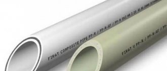
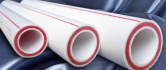
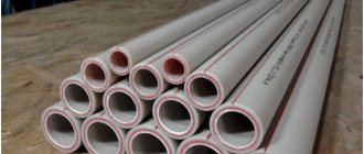
For hot water supply and heating systems, it is recommended to use reinforced polypropylene pipes. Pipes reinforced with fiberglass do not need to be stripped, since the mesh is located between layers of polypropylene, is not afraid of water and does not come into contact with the fitting. Aluminum foil used for reinforcement must be removed from the joint before welding. Aluminum in contact with water can cause electrochemical processes, which will lead to the destruction of the reinforcing film. In the case of external reinforcement, aluminum will interfere with the welding process of polypropylene elements. Therefore, pipes reinforced with aluminum foil need to be stripped. Types of stripping tools:
- manual - with removable, non-removable handles or corrugation;
- drill attachments.
Hand strippers and drill attachment
- For the outer layer, couplings with knives from the inside (material – tool steel), the so-called shaver, are used. The diameter of the tool is selected to match the diameter of the pipe being stripped. Double-sided couplings are often used to accommodate pipes of two different diameters.
Shaver for polypropylene pipes
- For the inner layer, trimmers are used. The knives are located at the inner end. You just need to insert the pipe into the tool, turn it several times and you can weld.
Trimmer for polypropylene pipes
Drill attachment
Drill attachments differ from manual strippers with a steel rod for installation in a drill, screwdriver or hammer drill. They are used to remove both the outer and inner reinforcing layers (the location of the knives determines the type of layer to be removed).
Heating circuit elements
Modern heating, which uses heating collectors, involves the creation of a large structure, which includes the following main elements:
- Source of thermal energy
. It is the first starting point from which the heated coolant is directed into pipelines and heating radiators. The power of heating units must be calculated as accurately as possible so that the equipment functions in accordance with its intended purpose.
The process of choosing a boiler and calculating its parameters is a very important point when creating a heating structure. An underestimated power indicator will not allow the circuit to work fully, as a result of which the rooms will not be warm enough. An overestimated value of the required heat transfer will lead to excessive fuel consumption, which will require the installation of control elements and, accordingly, additional financial costs;
Circulation pump
. A closed heating circuit with a comb requires forced circulation of the coolant. To do this, install circulation pumps in the heating system. thanks to which the necessary pressure is created to move the heated liquid, an optimal temperature is ensured, guaranteeing high-quality work.
When choosing a circulation pump, according to the instructions, a number of parameters are taken into account. The motor power of the circulation device is not one of the main indicators; it just determines the amount of energy consumed by the motor
Attention should be paid to the speed and volume of pumped liquid per unit of time
Pumps must be selected very carefully. The fact is that to ensure high-quality heating, it is necessary to select it with a power reserve that exceeds the design parameters by about 10 percent, since property owners often add a heating area without replacing the circulation device.
Cabinets
. This type of heating structure requires hiding its components, such as a do-it-yourself heating manifold, pipelines, ball valves, in drawers or cabinets specially equipped for this. They are either fixed outside or built into the walls.
The role of the device in wiring and its features
Heating systems made according to schemes that allow significant savings on pipes and shut-off valves are not sufficiently efficient. Given the significant rise in prices for coolants, their use is expensive for consumers. Running piping to the radiators using a manifold will change the situation. There will be no excess fuel consumption, the heating of each device is regulated.
The system acquires new functionality: safety and repairability are increased. Now, to eliminate a leak, you do not need to turn off the entire system and drain the water. They close the branch, eliminate the fault, and the heating in the remaining rooms continues to work.
The collector, which is also called a comb, is a cylindrical part that has one input and outputs connecting it to devices. The dimensions are unlimited and depend on the number of connected heating devices. Shut-off valves are installed on the pipes, which regulate the supply of coolant for each individual circuit. Two types of valves are used. Shut-off ball valves are usually used to shut off sections. They are not suitable as adjustment ones; a different type is required.
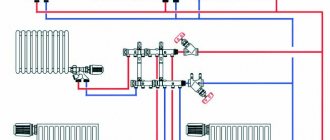
The work is carried out according to the following principle: coolant under forced pressure enters the device. From here it is distributed through outlets to radiators and heated floors. A collector circuit is used (also called radial), the essence of which is the parallel connection of consumers . Each has its own supply and return lines, which are equipped with fittings. Even when all appliances are turned on at the same time, the heating is uniform.
A circulation pump is used to create forced pressure. It is selected based on the area and number of floors of the house. If the system has a heated floor, greater performance is required because it creates increased resistance. The temperature difference at the inlet and outlet is reduced, heating is of better quality. Instead of control taps, it is possible to use thermostats, which guarantees precise heat supply. If the pipes are placed under a screed, an air valve is installed on each device.
Collectors are used with a variety of systems:
- Heating by radiators. Various connection schemes are used, but usually the bottom one is with polypropylene pipes, which are hidden under the covering or baseboards.
- Warm water floor. Mainly used as an auxiliary.
- Solar heating. In clear weather, it is possible to obtain 10 kW/hour of energy from one square meter of device.
With radial wiring, the temperature in each circuit is regulated separately, for which the required indicators are set on the thermostat. In a garage, 10° is enough, in a nursery, at least 20° is required, and for a heated floor, no more than 35°, otherwise it will be unpleasant to walk on it, and deformation of the coating is possible. In houses with several levels, the comb is installed on each floor.
Radial scheme and heated floor
The radial scheme allows you to combine a homemade heating collector and a “warm floor” system. But this design has a number of features.
Before you begin to create it, you need to familiarize yourself with them:
- the heating manifold must be installed on the condition that it is equipped with control valves and thermostatic valves on absolutely all circuits;
- When laying pipes for a “warm floor” heating system, electrothermal drives and thermostatic heads are certainly used. Thanks to these devices, “warm floors” will be able to quickly respond to changes in temperature and maintain the necessary microclimate in each room;
- The option for arranging a distribution system can be different - standard (made according to a standard scheme) and individual. The last method deserves special attention. In this case, the boiler operates in normal mode without significant temperature changes, and fuel is consumed economically.
Features and purpose
The collector is an important part of the water supply system in an apartment or private house. It performs an important function - it stabilizes the pressure in equipment that consumes water and, in fact, delivers it from the source to the consumer.
This could be, for example, a faucet or a toilet in an apartment. We can give a simple example, known to many. When someone is taking a shower, the water in the kitchen should not be turned on as this will cause a temperature change.
That is, a person in the bathroom can be scalded by hot water or cooled by cold water, depending on which kitchen tap was opened. If the apartment has a collector, such problems will not arise.
If a collector is installed in the heating system, the liquid is first supplied to the batteries through this device. The water pipeline works in a similar way: the central branch goes into one collector, and is not divided into a large number of branches.
Each branch has a shut-off valve
Next, we will consider in more detail the options, how the solution can be implemented, what installation rules exist and the very purpose of the collector in the apartment.
Classic wiring diagram
Any water supply system (household or apartment) is designed to supply water from the source to the consumer. And if there is only one consumer, the scheme is clear, but what if there are several of them?
Then, previously, they did it simply by inserting a T-shaped splitter into the pipe. The next consumer was connected to one outlet, and the water-consuming device was connected to the other.
This solution is quite widely used today in water supply systems for houses and apartments. After all, it has important advantages over others: simplicity of design, accessibility and short length of pipes.
But this approach also has disadvantages:
- difficult repairs - to carry out the procedure for one consumer, it is necessary to turn off the entire system;
- if several consumers are disconnected, the pressure in the system decreases significantly: the further “along the pipe” from the source, the worse the indicator. In such a situation, the closest consumer will actually be in a privileged position. An example of simultaneous water consumption in the bathroom and kitchen was given above.
Installation of plastic pipes
A plastic pipe can be connected to both plastic and metal. Of course, the methods of such connection differ from each other.
Types of polypropylene pipe connections
Speaking of options for joining polypropylene, you have a choice that depends on the availability of special equipment for soldering, as well as the nature of the section of pipeline that you will be installing.
Connection methods:
- Demountable threaded connection - for brands PN 10 and PN 16;
- Welding – for grades PN 20 and PN 25.
Threaded connections are used both for connecting plastic to plastic and plastic to metal. And if for plastic this is an alternative installation option, then for plastic with metal it is the only one. Solderless connections are made for cold non-pressure systems. This is done using compression fittings, and the connections themselves are additionally sealed.
Welding of polypropylene pipes with polypropylene
Let's take a closer look at the most common connection option - soldering. It allows you to get the most airtight and durable result, so it is used in any system.
Tools and materials
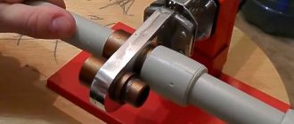
To make such a permanent connection, you need a special welding machine, which is also called a soldering iron. This device has special nozzles of different diameters with non-stick Teflon coating. This soldering iron can be purchased or rented. Professional options are very expensive, but you can get by with a simple option that makes seams no worse than expensive ones.
In addition to the soldering iron, you need: a pipe, fittings, a knife for plastic pipes, a tape measure and a pencil.
Attention! Under no circumstances should this coating be cleaned with metal scrapers, only with a tarpaulin rag or a wooden tool. Also teach that you need to clean the nozzle after each soldered part, but only in a warm state.
Welding stages
Important! Welding of polypropylene pipes occurs at 260ºС, so you need to use work gloves.
The welding process can be described step by step as follows:
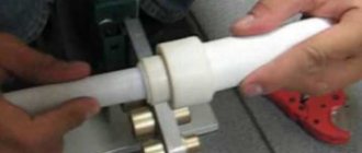
- Place of work . We install the welding machine (soldering iron) on the desktop and turn it on. You can also work directly at the pipeline location, depending on the task;
- Warming up . Turn on the soldering iron and wait until the nozzles are completely heated. A special diode beacon will indicate readiness; it usually takes about 20 minutes. The temperature of the soldering iron and the external temperature are important: a) you cannot work with an unheated soldering iron - the elements will not achieve the necessary ductility and will not join into a strong seam; b) you cannot work at sub-zero ambient temperatures;
- Preparing parts . We cut off the required section of pipe with special scissors, doing it at a right angle. Now, with a pencil (marker), we make a mark on the pipe equal to the depth of the fitting, so that when connecting we do not overdo it with pressure - we connect exactly to the mark. The joints must be treated with degreasing agents: alcohol or acetone. Secret! To make connections as easy as possible, the end of the pipe is treated with a chamfer.
- Heating of parts . The pipe and fitting are simultaneously inserted into the heated nozzles and wait for a certain time. Waiting time is determined intuitively by professionals, but there are special tables for this;
- Connection . We insert the pipes into the fitting up to the mark, wait a while and leave to cool. It is important to wait until it cools completely, since any deformation is extremely undesirable. Such things are corrected exclusively “surgically” - by cutting out the fitting and re-soldering the parts.
Features of the radial scheme of heating collectors
The design of a heating manifold made of polypropylene, which is shown in the photo, can be considered optimal in the case where the house has several floors or the building has a large number of rooms and utility rooms.
Thus, the connection diagram for the heating collector implies that it will be installed on each floor (sometimes there may be several of them), and pipes will be laid from it. As a rule, the instructions stipulate that the installation of heating system elements is carried out in walls or cement screed.
The design of the heating structure and its branches should be drawn up before starting repair work, so as not to damage the base for laying the floor covering later.
The principle of operation of the elevator
The principle of operation of the elevator
The elevator unit is a fairly large container, somewhat similar to a pot. But this is not the elevator itself, although it is called that. This is a whole unit, which also includes:
- Dirt traps - after all, the water coming from the pipe is not entirely clean.
- Magnetic mesh filters - the unit must ensure a certain purity of the coolant so that batteries and pipes do not become clogged.
Having been purified, the hot water flows through the nozzle into the mixing chamber. Here it moves at high speed, as a result of which water is sucked in from the return circuit, which is connected to the mixing chamber on the side. The process of suction, or injection, occurs spontaneously. It is now clear that by changing the diameter of the nozzle, you can regulate both the volume of coolant supplied and its temperature at the exit from the elevator.
As you understand, for a heating system, an elevator is a pump and a mixer at the same time
And what is important - no electricity
There is one more point that experts pay attention to - this is the ratio of the pressure inside the supply pipeline and the resistance of the elevator. This ratio should be 7:1. Only this ratio ensures the efficiency of the entire system.
But that's not all there is to efficiency.
Pay attention to the fact that the pressure inside the system - and this is the supply and return circuits - must be the same. It is acceptable if it is a little less in the return
But if the difference is significant, for example, in the supply pipeline it is 5.0 kgf/cm2, and in the return pipeline it is below 4.3 kgf/cm2, this means that the pipeline system and heating devices are clogged with dirt.
Connection diagram for an adjustable water-jet elevator
Another possible reason is that during a major overhaul the pipe diameters were changed downward. That is, the contractor saved money in this way.
Is it possible to regulate the temperature of the coolant? It is possible, and for this it is better to use an adjustable water-jet type elevator.
The design of such a device includes a nozzle, the diameter of which can be changed. Sometimes the adjustment range, and this applies more to foreign analogues, is quite large, which is not so necessary. Domestic elevators have a smaller range shift, but, as practice has shown, this is enough for all occasions.
True, adjustable elevators are rarely installed in residential buildings. Their installation in public or industrial premises is much more effective. With their help, you can save up to 25% on heating costs just because they allow you to reduce the temperature at night, as well as on weekends and holidays.
To work with polypropylene systems you will need a simple set of tools
It will include scissors for working with plastic pipes, a rag for wiping pipes from dirt and dust, and a soldering iron for polypropylene pipes. There are a lot of soldering irons on the market, everyone chooses according to their needs for work around the house. It is not necessary to buy an expensive product; a household appliance will suffice.
Let's start soldering.
The soldering iron is plugged into the outlet, the temperature is set using the regulator from 280 degrees depending on the diameter, I will now set it to 270 degrees. The fact that the soldering iron has heated up is indicated by a green indicator, you can begin the soldering process. But what if the pipe contains dirt, you need to wipe it thoroughly with a rag. To connect pipes, we take the connecting parts directly from the pipe, one pipe nozzle 2 for the fitting, and at the same time insert it into the soldering iron elements until it stops.
I hold it for no more than 5 seconds, at the same time remove it and immediately connect it all the way, our connection is ready. To prevent the soldering iron from smoking, as long as polypropylene particles remain on it, the nozzles can be wiped with a rag. After two minutes, the connection has completely cooled down and further installation can begin. I want to tell you how pipes are soldered into a manifold, we take a manifold, a pipe of a suitable diameter and solder it according to the old scheme, we immediately need to check the alignment, the angle should be 90 degrees.
It is not recommended to bend the pipe at the connection; this will be a mistake. To change from one diameter to another we will use a transition coupling. For example, we need to switch from diameter 25 to 20. First, I prepare the transition coupling in a pipe with diameter 25; rotating the fittings during preparation is prohibited, the connection cools down and we can directly solder the pipe of a smaller diameter. I check the evenness, our transition is ready.
Pipe selection
Before starting work directly related to the creation of a heat supply system, it is necessary to coordinate the main parameters of the pipelines. First of all, the source of thermal energy, the inlets and outlets to the collector, as well as the pipeline must be of the same diameter. Otherwise, when using pipes of different diameters, adapters are used. Their installation requires additional material costs and time for installation.
The supply and return pipes through which the coolant liquid moves are made from different materials, but experts recommend using polypropylene pipes (for more details: “Do-it-yourself installation of a heating system from polypropylene pipes”).
Their advantage lies in their availability, practicality and ease of use during installation work. The selection of polypropylene pipes should be carried out on the basis of hydraulic calculations.
Failure to comply with the required diameters for pipes leads to such negative consequences as:
- violation of coolant circulation;
- airing of the heating circuit;
- uneven heating.
Classification of fittings and adapters
Assembling pipelines using special nozzles is the most popular method of wiring engineering systems. In order to select the necessary types of fittings for polypropylene pipes, you should familiarize yourself with their detailed classification.
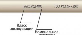
For the manufacture, release and supply of technical polypropylene products, the provisions of state standard No. 52134 of 2003 are used.
Types of fittings for polypropylene pipes Source ecomont.ru
Polypropylene pipes manifold Far
Hello dear forum users! Sorry if I'm raising a question that has already been discussed.
New multi-apartment building, polypropylene risers, they decided to make the wiring also with polypropylene (diameter 20). I would like to install Far manifolds. After a long study of forum topics and product range, my head is a mess. We are interested in adjustable collectors 3/4″ 1/2″ outlets (3 - DHW and 2+3 - cold water outlets). As it turned out, the bends come with metric threads and pipe threads; pipe threads are divided into Eurocone and Flat-Faced. Flat-Faced, as I understand it, is ideal for me, but it’s not possible to find them in Rostov (it’s probably too late to order).
Explain what is better to take with TR or MR. As far as I understand, the MR leads are attached via an MR-TR adapter, and on the TR there is already a fitting adapter for soldering polypropylene. With TR, you can straight away fit the fitting, but there are sharp edges that can cut through the gasket.
This is such a mess. Don't throw stones at me, I don't know anything about plumbing.
Those who do the repairs have never done the wiring with the collector, so they made the choice themselves. Today it was proposed to make a prefabricated manifold from polypropylene tees (in one place, the distance between the terminals is minimal, as in a regular manifold (not enough space), i.e., it looks like a regular manifold), and hang taps on the bends. In this regard, more questions have arisen:
- How much less (or more?) reliable will such a collector be?
- Tees are not reinforced, how bad is that? (reinforced pipes)
- The taps on the bends (also made of polypropylene) as far as I understand are ball valves, i.e. Can't regulate? only close - open? Are polypropylene faucets adjustable?
I'm leaning towards Far collectors, but if the connections on the taps are a weak point, maybe a prefabricated one would be better?
www.mastergrad.com
Manifold assembly – Good-natured Plumber
I have already written about why a collector is needed. I also wrote about Eurocones, which are used in conjunction with collectors.
In this material I will briefly talk about assembling a manifold for polypropylene pipes using an American detachable connection.
This is what the assembled product looks like:
We take the American one and put the part with the union nut aside. We need to screw the second part onto the collector. Seal the manifold thread:
We bait the main part of the American woman:
And then tighten it with a key. This can be an open-end or adjustable wrench. But it’s still more convenient to do this with a socket wrench or a head:
We do the same with the remaining taps:
If the product will be in a visible place, then it would be correct to make all connections clean. For example, like here, these joints are sealed with flax, but the flax is not visible:
Before soldering the American ones, do not forget to make sure that the union nut is positioned correctly.
Before tightening the cap, you need to install a flat gasket, which is included in the American kit. So, this same gasket is different on both sides. On one side it seems to be oiled, and on the other it is dry. I usually put the oiled side on polypropylene, and the dry side on metal. Thus, when tightening the union nut, the polypropylene connection does not “twist”
dretun.ru
