A single-pipe heating system is one of the solutions for laying pipes inside buildings with the connection of heating devices. This scheme seems to be the simplest and most effective. The construction of a heating branch using the “one pipe” option is cheaper for homeowners than other methods.
To ensure the operation of the scheme, it is necessary to perform a preliminary calculation of a single-pipe heating system - this will allow you to maintain the desired temperature in the house and prevent a loss of pressure in the network. It is quite possible to cope with this task on your own. Do you doubt your abilities?
We will tell you what the design features of a one-pipe system are, give examples of working diagrams, and explain what calculations must be performed at the planning stage of the heating circuit.
Strengths and weaknesses of single pipe systems
The popularity of single-pipe heating in private construction is explained by the fairly low cost of the structure and the ability to independently carry out installation work.
This makes it possible to save on hiring specialists. Among other advantages of single-pipe systems, the following should be highlighted:
- High level of hydraulic stability. If you turn off some of the circuits, this will not affect the heat transfer of the remaining elements of the system. The same applies to replacing batteries or increasing the number of their sections.
- Low pipe consumption for organizing a main line.
- Slight inertia. To heat up the system, an order of magnitude less coolant is required than in schemes with two pipes.
- External aesthetics. Installation of a single-pipe system usually does not affect the beauty of the interior of the room, especially when using hidden laying of the main pipe.
- Thanks to the use of innovative shut-off valves (automatic and manual thermostats), it is possible to fine-tune the operating modes of the heating circuit and its constituent devices.
- Simplicity and reliability of the design, which makes it possible to install a single-pipe heating system on your own. The same applies to heating maintenance during operation.
By organizing the connection of control and monitoring devices for the heating system, it is possible to achieve its functioning in automatic mode. Integration into the Smart Home system is also allowed: as a result, it becomes possible to program optimal heating modes, taking into account the time of day, season, etc.
The main disadvantage of a single-pipe heating scheme is the presence of an imbalance between the heating of the radiators, depending on their distance from the boiler. This is explained by the gradual cooling of the coolant as it circulates through the pipes. As a result, the batteries closest along the coolant path turn out to be hotter than those located further away. In such cases, it is better to use cast iron devices, which are characterized by slow cooling.
How to work in EXCEL
Using Excel tables is very convenient, since the results of hydraulic calculations are always reduced to tabular form. It is enough to determine the sequence of actions and prepare exact formulas.
Entering initial data
Select a cell and enter a value. All other information is simply taken into account.
- the D15 value is recalculated in liters, this makes it easier to perceive the flow rate;
- cell D16 - add formatting according to the condition: “If v does not fall within the range of 0.25...1.5 m/s, then the cell background is red/the font is white.”
For pipelines with a difference in inlet and outlet heights, static pressure is added to the results: 1 kg/cm2 per 10 m.
Registration of results
The author's color scheme carries a functional load:
- Light turquoise cells contain the original data - they can be changed.
- Pale green cells are entered constants or data that is little subject to change.
- Yellow cells are auxiliary preliminary calculations.
- Light yellow cells—calculation results.
- Fonts: blue - original data;
- black - intermediate/non-main results;
- red - the main and final results of the hydraulic calculation.
Results in Excel table
Example from Alexander Vorobyov
An example of a simple hydraulic calculation in Excel for a horizontal pipeline section.
- pipe length 100 meters;
- ø108 mm;
- wall thickness 4 mm.
Table of local resistance calculation results
By complicating calculations in Excel step by step, you better master the theory and partially save on design work. Thanks to a competent approach, your heating system will become optimal in terms of costs and heat transfer.
Features of a single-pipe heating wiring diagram
Simplicity and practicality are the main advantages of single-pipe wiring. The heating circuit, one or more, is formed by one pipe tied to the boiler. Radiators are connected to the pipe in series.
Each of them is tapped into a common pipe of the circuit by tees, and the section between the insertion points of each heat exchanger is replaced with a pipe of smaller diameter, forming a bypass.
This scheme is called Leningradka in everyday life and is suitable for most one-story private houses with an area of no more than 80 m2.
Depending on the location of the radiators, the number of storeys in the building, single-pipe wiring is selected:
- With bottom wiring;
- With top wiring.
Depending on the number of storeys of the house:
- Horizontal;
- Vertical.
And according to the type of coolant circulation:
- With forced circulation;
- With natural circulation (gravity).
Basic options are listed, which can be combined if necessary to obtain a complete heating system and cover all heated premises. For houses with a large area or two or three floors, several parallel circuits are formed, in each of which a single-pipe connection is organized.
It is important to balance the contours to ensure even heat distribution. For this purpose, control valves or hydraulic arrows, manifold groups are used
The single-pipe wiring diagram is attractive for its efficiency, but at the same time it has obvious disadvantages. The radiators in the circuit are connected in series, which means that the boiler coolant alternately enters the heat exchangers.
Having lost some of the heat in the first battery, cooled water already flows to the subsequent ones, which reduces their thermal power.
Bypass connection diagram
This problem can be resolved in several universal ways:
- Each subsequent radiator in the circuit is selected with a large number of sections so that the final power meets the requirements, taking into account the reduced coolant temperature. However, this option increases the temperature gradient at the beginning and end of the circuit and saves only if the total number of heat exchangers in the circuit does not exceed 6-7;
- The presence of bypasses on each radiator, as well as a circulation pump, can significantly reduce the temperature difference. By creating a sufficiently large pressure, it is possible to achieve uniform distribution of the hot coolant throughout the main pipe, which means that more heat will flow to each radiator.
Naturally, with forced circulation, the heating system becomes energy-dependent, but more efficient.
For large houses, you can always divide the overall circuit into several smaller ones with parallel connection and even with a separate pump for each of them.
With bottom wiring
The usual single-pipe Leningradka circuit is a clear example of lower wiring. From the boiler the pipe goes at floor level or even in the basement. In an effort to save on materials, you should use bottom wiring.
System diagram with bottom wiringIn two- or three-story buildings, the lower wiring also determines the position of the supply and return for the risers. The pipe from the boiler goes down, and the coolant rises through the riser before entering the circuits distributed across the floors.
With top wiring
Scheme with top wiring 1. Direct 2. Radiator 3. Return 4. Air vent 5. Thermal head
Top wiring is relevant for a vertical single-pipe circuit. The supply from the boiler is supplied to the risers from above. From the boiler, the collector rises to the attic or to the ceiling of the upper floor and there it is already connected to the upper circuit and lowered to the lower one.
In a private house, overhead wiring does not provide any particular advantages; moreover, by heating the upper floor with hotter coolant to the detriment of the lower floor, the air temperature gradient in the house is further enhanced.
Vertical
Risers are distributed throughout the building near each window opening or between them. The risers form a series of parallel circuits, in each of which the radiators are connected on the side in series with the bypass.
Horizontal
Horizontal wiring diagram of the system
Optimal wiring diagram for one-story or two-story houses. The circuit pipe is laid around the perimeter of the building, and radiators with bottom connections cut into it. The area between the insertion points of each radiator, a common pipe, is mounted with a smaller diameter, forcing part of the coolant to pass through the heat exchanger.
To cover two or more floors, two supply and return risers go from the boiler, and on the floors a circuit of one pipe is distributed separately around the perimeter.
With this distribution, there is no rigid connection to the installation location between the radiators on the first and second floor.
Data collection and preparatory calculations
First of all, let’s answer what is hydraulic calculation needed for?
- For efficient heating of all rooms, regardless of external and internal air temperatures.
- To reduce operating costs that arise during the operation of heating equipment.
- To reduce costs associated with the purchase of equipment and materials. This concerns the competent selection of pipeline diameters in each section of the heating system.
- To reduce the noise level associated with the movement of coolant along the circuit.
- For stable operation of the heating system.
In order to make a calculation of the heating system (this story will talk exclusively about a single-pipe scheme with forced circulation of the coolant), it is necessary to obtain the following data:
- The required power of the heat generator.
- Power and number of radiators for each heated room.
- Diameter and length of the heating circuit.
Having the required data in hand, you can proceed to selecting a circulation pump, calculating the amount of coolant, the capacity of the expansion tank and setting up the safety group. Now let's talk about everything in order.
Schemes with different coolant supply to radiators
Depending on the position of the risers for supplying water to the batteries, vertical and horizontal wiring are distinguished. In private one-story houses, a horizontal wiring diagram is used. During installation, water inlet and outlet pipes can be successfully integrated into the interior, hidden in niches or under the floor.
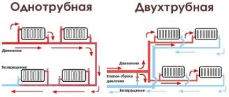
The flow of hot and chilled water in the heating system of a private home can be installed using one or two pipes. Each option has nuances of the wiring type, positive aspects and disadvantages.
Single-pipe scheme
This is an easier to install and cheaper option. The heating system with one pipe is a ring with installed radiators. Warm water moves around the perimeter and eventually returns to the boiler. The coolant transfers several degrees of heat to each radiator. This means that the further the heating device is located from the boiler, the lower the water temperature and the ability to heat the room. You can increase water heating. This will require more fuel consumption. Installing a circulation pump will help move water at a faster speed and distribute heat evenly. The optimal solution with this scheme would be to increase the number of sections of the last batteries in the line.
Radiators are usually connected through a bypass (bypass pipe), which will allow you to turn off any of them without stopping the flow of coolant. The system does not require the installation of fittings and taps, which minimizes the risk of accidents.
Advantages of the scheme:
- minimizing the pipe perimeter;
- savings on system elements;
- fast, easy installation.
Two-pipe scheme
Installing heating in a private house using two pipes works more efficiently. With this scheme, each radiator has a separate coolant supply from the heat main, but the heat main, as in the previous case, is the same for the entire system. The difference is that radiators are connected to the systems in parallel, rather than in series.
The system has one return flow line - a separate pipe departs from each battery to remove the coolant.
We invite you to watch a detailed video about the nuances of installing a two-pipe heating system in a house:
Beam system
The collector beam system involves the installation of a collector through which the coolant is distributed throughout the system. Each heating battery has its own pipes for supplying coolant and discharging it directly from the boiler. Each circuit is cut off by shut-off valves. This makes the system easier to use and repair. Without disconnecting the entire system, you can repair a separate circuit or radiator.
The downside is significant costs for materials. You will need shut-off valves, pipes, adjustment devices, and monitoring sensors.
The radial circuit with a distributor operates under good pressure in the pipe created by a circulation pump.
The collector evenly distributes the coolant flow. The device consists of two combs. One receives hot water from the boiler. Another comb collects the cooled water and sends it back to the boiler. How to calculate heating in a private house with this scheme?
Calculating parameters, drawing up a project, and regulating power during use are facilitated by connecting radiators in parallel. This ensures a minimum difference in water temperatures around the perimeter of the circuit. The system is controlled from one place with installed indicators, taps, pumps and valves.
Installation of a beam system is the most expensive in terms of the total cost of components and requires certain qualifications. You should draw up a project and install radiant heating during construction or general renovation. This is due to the fact that the pipes are installed in the floor screed.
Determination of pressure loss in pipes
The pressure loss resistance in the circuit through which the coolant circulates is determined as its total value for all individual components. The latter include:
- losses in the primary circuit, denoted as ∆Plk;
- local coolant costs (∆Plм);
- pressure drop in special zones called “heat generators” under the designation ∆Ptg;
- losses inside the built-in heat exchange system ∆Pto.
After summing these values, the desired indicator is obtained, characterizing the total hydraulic resistance of the system ∆Pco.
In addition to this generalized method, there are other methods for determining pressure loss in polypropylene pipes. One of them is based on a comparison of two indicators tied to the beginning and end of the pipeline. In this case, the pressure loss can be calculated by simply subtracting its initial and final values, determined by two pressure gauges.
Another option for calculating the required indicator is based on the use of a more complex formula that takes into account all the factors that affect the characteristics of the heat flow. The ratio given below primarily takes into account the loss of fluid pressure due to the large length of the pipeline.
- h – liquid pressure loss, in the case under study measured in meters.
- λ – coefficient of hydraulic resistance (or friction), determined using other calculation methods.
- L is the total length of the serviced pipeline, which is measured in linear meters.
- D – internal pipe size, which determines the volume of coolant flow.
- V is the speed of fluid flow, measured in standard units (meter per second).
- The symbol g is the acceleration due to gravity, equal to 9.81 m/s2.
Pressure losses occur due to friction of the fluid against the inner surface of the pipes.
Of great interest are the losses caused by the high coefficient of hydraulic friction. It depends on the roughness of the internal surfaces of the pipes. The ratios used in this case are valid only for pipe blanks of a standard round shape. The final formula for finding them looks like this:
- V is the speed of movement of water masses, measured in meters/second.
- D is the internal diameter, which determines the free space for the coolant to move.
- The coefficient in the denominator indicates the kinematic viscosity of the liquid.
The last indicator refers to constant values and is found using special tables published in large quantities on the Internet.
Types of heating systems with gravity circulation
Despite the simple design of a water heating system with self-circulation of coolant, there are at least four popular installation schemes. The choice of wiring type depends on the characteristics of the building itself and the expected performance.
To determine which scheme will work, in each individual case it is necessary to perform a hydraulic calculation of the system, take into account the characteristics of the heating unit, calculate the diameter of the pipe, etc. You may need professional help when performing the calculations.
Closed system with gravity circulation
In EU countries, closed systems are the most popular among other solutions. In the Russian Federation, the scheme has not yet received widespread use. The operating principles of a closed-type water heating system with pumpless circulation are as follows:
- When heated, the coolant expands and water is displaced from the heating circuit.
Under pressure, the liquid enters a closed membrane expansion tank. The design of the container consists of a cavity divided by a membrane into two parts. One half of the tank is filled with gas (most models use nitrogen). The second part remains empty for filling with coolant.
When the liquid is heated, pressure is created sufficient to push through the membrane and compress the nitrogen. After cooling, the reverse process occurs and the gas squeezes water out of the tank.
Otherwise, closed-type systems work like other heating schemes with natural circulation. The disadvantages include the dependence on the volume of the expansion tank. For rooms with a large heated area, you will need to install a spacious container, which is not always advisable.
Open system with gravity circulation
The open type heating system differs from the previous type only in the design of the expansion tank. This scheme was most often used in old buildings. The advantage of an open system is the ability to independently manufacture a container from scrap materials. The tank usually has modest dimensions and is installed on the roof or under the ceiling of the living room.
The main disadvantage of open structures is the entry of air into pipes and heating radiators, which leads to increased corrosion and rapid failure of heating elements. Airing of the system is also a frequent “guest” in open-type circuits. Therefore, radiators are installed at an angle; Mayevsky valves must be provided to bleed air.
Single-pipe self-circulating system
A single-pipe horizontal system with natural circulation has low thermal efficiency and is therefore used extremely rarely. The essence of the circuit is that the supply pipe is connected in series to the radiators.
The heated coolant enters the upper branch pipe of the battery and is discharged through the lower outlet. After this, the heat flows to the next heating unit and so on until the last point. The return flow returns from the outermost battery to the boiler.
This solution has several advantages:
- There is no pair pipeline under the ceiling and above the floor level.
Saves money on system installation.
The disadvantages of this solution are obvious. The heat transfer of heating radiators and the intensity of their heating decreases with distance from the boiler. As practice shows, a single-pipe heating system for a two-story house with natural circulation, even if all slopes are observed and the correct pipe diameter is selected, is often redone (by installing pumping equipment).
Two-pipe self-circulating system
A two-pipe heating system in a private house with natural circulation has the following design features:
- Supply and return flow through different pipes.
The supply pipeline is connected to each radiator through an inlet branch.
The second line connects the battery to the return line.
As a result, a two-pipe radiator-type system provides the following advantages:
- Even heat distribution.
No need to add radiator sections for better heating.
Easier to adjust the system.
The diameter of the water circuit is at least one size smaller than in single-pipe circuits.
Lack of strict rules for installing a two-pipe system. Small deviations regarding slopes are allowed.
The main advantage of a two-pipe heating system with bottom and top wiring is the simplicity and at the same time efficiency of the design, which allows you to eliminate errors made in calculations or during installation work.
A few additional tips
Longevity is largely influenced by the materials from which the main parts are made. Preference should be given to pumps made of stainless steel, bronze and brass. Pay attention to what pressure in the system the device is designed for.
Although, as a rule, there are no difficulties with this (10 atm is a good indicator). It is better to install the pump where the temperature is minimal - before entering the boiler. It is important to install a filter at the entrance. It is advisable to position the pump so that it “sucks” water from the expander. This means that the order in the direction of water movement will be as follows: expansion tank, pump, boiler.
Conclusion
So, in order for the circulation pump to work for a long time and conscientiously, you need to calculate its two main parameters (pressure and productivity).
You should not strive to comprehend complex engineering mathematics.
At home, an approximate calculation will be enough. All resulting fractional numbers are rounded up.
Number of speeds
To control (switch gears), a special lever on the unit body is used. There are models that are equipped with a temperature sensor, which allows you to fully automate the process. To do this, you do not need to manually switch speeds; the pump will do this depending on the room temperature.
This technique is one of several that can be used to calculate pump power for a specific heating system. Specialists in this field also use other calculation methods that allow them to select equipment based on power and pressure created.
Many owners of private houses may not try to calculate the power of the circulation pump for heating, since when purchasing equipment, as a rule, specialist assistance is offered directly from the manufacturer or a company that has entered into an agreement with the store.
When choosing pumping equipment, it should be taken into account that the necessary data for carrying out calculations must be taken from the maximum that the heating system can, in principle, experience. In reality, the load on the pump will be less, so the equipment will never experience overload, which will allow it to work for a long time
But there are also disadvantages - higher electricity bills.
But on the other hand, if you choose a pump with less power than required, then this will not affect the operation of the system in any way, that is, it will operate normally, but the unit will fail faster. Although your electricity bill will also be lower.
There is one more parameter by which you should choose circulation pumps. You may notice that in the assortment of stores there are often devices with the same power, but with different dimensions.
You can calculate the heating pump correctly, taking into account the following factors:
- 1. To install equipment on conventional pipelines, mixers and bypasses, you need to select units with a length of 180 mm. Small devices 130 mm long are installed in hard-to-reach places or inside heat generators.
- 2. The diameter of the supercharger pipes should be selected depending on the cross-section of the main circuit pipes. At the same time, it is possible to increase this indicator, but it is strictly forbidden to decrease it. Therefore, if the diameter of the main circuit pipes is 22 mm, then the pump pipes should be 22 mm and above.
- 3. Equipment with a pipe diameter of 32 mm can be used, for example, in heating systems with natural circulation for its modernization.
Operating principle of water heating
In low-rise construction, the most widespread is a simple, reliable and economical design with one highway. The single-pipe system remains the most popular way of organizing individual heat supply. It operates due to the continuous circulation of the coolant liquid.
Moving through pipes from the source of thermal energy (boiler) to the heating elements and back, it releases its thermal energy and heats the building.
The coolant can be air, steam, water or antifreeze, which is used in periodic residences. The most common are water heating schemes.
Traditional heating is based on the phenomena and laws of physics - thermal expansion of water, convection and gravity. When heated by the boiler, the coolant expands and creates pressure in the pipeline.
In addition, it becomes less dense and, accordingly, lighter. Pushed from below by heavier and denser cold water, it rushes upward, so the pipeline leaving the boiler is always directed as high as possible.
Under the influence of the created pressure, convection forces and gravity, water flows to the radiators, heats them, and cools itself.
Thus, the coolant releases thermal energy, heating the room. The water returns to the boiler already cold, and the cycle begins again.
Modern equipment that provides heat to a home can be very compact. You don’t even need to allocate a special room to install it.
A heating system with natural circulation is also called gravity and gravity. To ensure the movement of liquid, it is necessary to observe the slope angle of the horizontal branches of the pipeline, which should be equal to 2 - 3 mm per linear meter.
When heated, the volume of coolant increases, creating hydraulic pressure in the line. However, since water is not compressed, even a slight excess will lead to the destruction of heating structures.
Therefore, in any heating system a compensating device is installed - an expansion tank.
In a gravity heating system, the boiler is mounted at the lowest point of the line, and the expansion tank at the highest. All pipelines are made downhill so that the coolant liquid can move by gravity from one element of the system to another
Quick selection of pipe diameters from the table
For houses up to 250 sq.m. provided that there is a 6-piece pump and radiator thermal valves, you don’t have to do a full hydraulic calculation. You can select the diameters from the table below. On short sections you can slightly exceed the power. Calculations were made for coolant Δt=10oC and v=0.5m/s.
| Pipe | Radiator power, kW |
| Pipe 14x2 mm | 1.6 |
| Pipe 16x2 mm | 2,4 |
| Pipe 16x2.2 mm | 2,2 |
| Pipe 18x2 mm | 3,23 |
| Pipe 20x2 mm | 4,2 |
| Pipe 20x2.8 mm | 3,4 |
| Pipe 25x3.5 mm | 5,3 |
| Pipe 26x3 mm | 6,6 |
| Pipe 32x3 mm | 11,1 |
| Pipe 32x4.4 mm | 8,9 |
| Pipe 40x5.5 mm | 13,8 |
Discuss this article, leave a review in | |
Pipeline installation
Installation of a heating pipeline in a private house involves connecting individual elements into a single system. Perform the following operations:
- layout of elements according to the diagram;
- welding or soldering of pipes;
- connection using fittings;
- connection of heating devices.
Since plastic materials expand when heated, expansion joints are installed. This is a loop of pipe that is soldered into the pipeline on long straight sections. After completion of installation work, it is necessary to carry out a test under operating pressure.
How to solder a heating pipeline
We will describe below how to properly solder heating from propylene pipes. When polypropylene is heated to +260 degrees, it melts, which makes it possible to connect individual elements. This is ensured by the phenomenon of polyfusion - the interpenetration of atoms. We get the junction of two parts that are not separated by a border.
The soldering iron is selected depending on the type of soldering - butt, coupling or fitting. It has nozzles onto which sections of pipes to be connected or a pipe and fitting are put on. After heating, they are tightly connected and held for 4-6 seconds. The heating and cooling time of the connected polypropylene elements depends on their diameter. The data is given in the table, which can be found in the specialized literature.
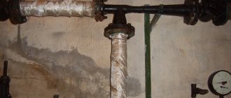
Attaching the pipeline to the wall
The pipeline is secured to the wall using clips and clamps. Clips ensure that the pipe remains stationary along its axis.
They are attached to the wall with a clamp, placing the pipes no closer than 20 mm from it. Fasteners are placed at a distance of no more than one and a half meters from each other. In places where pipes turn or branch, additional fasteners are installed.
Radiator mounting
Radiators are hung on metal brackets included in the delivery kit and secured to the wall with dowels. Their thickness depends on the weight of the battery. Cast iron elements are additionally supported by legs.
Heating schemes made of polypropylene for a private house
- single-pipe or double-pipe;
- two-pipe with horizontal wiring;
- two-pipe with vertical wiring;
- collector
The single-pipe scheme provides for the passage of liquid in one direction. It is used when connecting radiators in series. The two-pipe model has a return line.
Two-pipe circuit with horizontal wiring
In this scheme, polypropylene pipes are located along the wall just above the floor level, which makes them inconspicuous and does not disturb the aesthetics of the room. This is a conventional two-pipe system with bottom wiring. Most often, heating radiators are installed around the perimeter of the room.
Vertical wiring diagram
The vertical layout is used for heating manor houses with 2 floors or more. The heated liquid is transported between floors via risers. The layout can be upper or lower in relation to the radiator. The upper model is more often used with natural circulation. On each floor you can make a horizontal heat distribution scheme. In this case, one riser is installed, through which the coolant will be transferred to each floor.
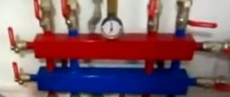
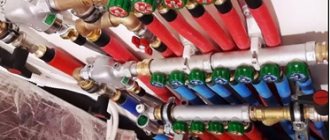
Using the distribution manifold
In a heating model with forced circulation, a collector is often installed. In it, a comb of pipes extends from the main riser; their number is equal to the number of heat consumers. Each polypropylene pipe has a separate valve that turns off a specific line. This system allows you to distribute heat evenly and, if necessary, reduce the temperature in a private home.
The disadvantage is the high cost of installation, as the length of the pipeline and the number of fittings increases. However, it is convenient to operate; it is possible to separately turn off the damaged area. Complex collectors are equipped with automatic devices that regulate the temperature of the coolant and turn off the system in an emergency.
One of the methods of heating a home is a water heated floor. Polypropylene pipes are widely used for its installation. The water floor heating system is connected to the main heating network.
Organizing the heating of a manor house is a complex process. To do it yourself, you need to study methods and models of pipe laying, select suitable materials and fittings. It would be a good idea to familiarize yourself with heating projects for residential buildings that are similar in design and size to your home.
370
Connection
In double-circuit heating, one of three methods of connecting batteries is used: one-sided, diagonal or bottom. The best method is considered to be a diagonal connection. This way you can achieve maximum heat transfer from heating equipment (up to 98% of the nominal value).
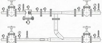
The general diagram of pipe routing and connection of heating devices, boiler and shut-off devices for a one- or two-story house may look like this:
- Despite all the differences between the methods of connecting batteries, they are all used in practice, but with different tasks. In particular, the connection using the bottom method is not very productive, but it is a good option if the pipe needs to be placed under the floors.
- Hidden pipeline installation can also be used in one-sided and diagonal schemes; however, in these cases, large sections of the pipeline will remain visible, which can only be hidden under wall cladding.
- Connecting side-type batteries is practiced when the number of sections is limited to 15 elements - there is almost no heat loss in this case.
Common installation mistakes
Above are “Leningrad” diagrams of horizontal single-pipe floor circuits with radiators connected to a common main line by two tees. Only part of the total volume of coolant circulating through the circuit flows through each device. You may encounter an erroneous connection without a main pipe (see the outline of the first floor in the figure below).
Types of connection of radiators in horizontal single-pipe circuits.
This method of connecting heating radiators is extremely cheap. Each radiator has one fitting for connecting a DN20 or DN25 metal-plastic pipe and a section of pipe between adjacent devices. Can't think of anything cheaper. But the price to pay for the cheapness is poor performance of half the radiators. The first of them (in the direction of the coolant movement) is heated to a temperature of 55 ° C, and the last one at N = 6-8 is heated to only 35 ° C, since the coolant, passing through the radiators, intensively cools down in them.
Calculation of the number and power of batteries
Both in single-pipe connection of heating radiators and in two-pipe schemes, the heating efficiency of a particular room depends not only on the number of radiator sections, their design, the material from which they are made, surface area and method of connection to the main pipeline, but also on the material of the walls and insulation method, heat loss in windows, etc.
Let's use the recommended data that can be found in specialized literature. 1 m3 in a brick house requires approximately 0.034 kW of heat to maintain a comfortable temperature; in a house made of SIP panels – 0.041 kW; in a brick house with insulated: ceiling, attic, load-bearing walls, foundation - 0.02 kW.
For example, let's consider the selection of batteries for a room of 18 m2 with a ceiling height of 2.5 m in a brick house. (0.034 kW).
- Let's find out the volume of the room: 18 x 2.5 = 45 m3.
- We calculate how much thermal energy is needed for a given room: 45 x 0.034 = 1.53 kW
Now you need to use the table with battery characteristics.
The figure shows the main characteristics of the most common radiators. Based on the data presented, aluminum batteries have the best performance-to-cost ratio. We need data on the power of one section, the lower limit of which is 0.175 kW.
- We divide the result by the power of the section of the selected type of radiator and get the number of sections: 1.53 / 0.175 = 8.74
Bottom line: to heat a room of 45 m3, we need an aluminum radiator consisting of 9 sections. Carry out similar calculations for each room in the house.
Common mistakes when choosing components
The most important mistake of the master is trying to install a single-pipe heating system in a house whose area exceeds 100 square meters. If you install too many radiators on one circuit, it will not work efficiently. Another mistake is choosing a boiler with unequal efficiency. If it is too low, the building will be cold; if it is high, fuel consumption will increase.
It is considered an error to connect batteries using corners and in the absence of jumpers. If you do this, the heating of the room will be uneven, and if one radiator breaks down, you will have to stop the entire system.
If you select a pipe diameter that is too large, the circuit will not operate efficiently.
Which boiler is better to choose
The best option for a single-pipe Leningrad system is a gas boiler. Despite the fact that it must be installed by specialized services, it is small in size, equipped with automation, and fuel is one of the cheapest. There are other options:
| Type of equipment | Characteristic |
| Wood-burning | It is large in size and requires a separate room for installation. Fuel must be manually loaded periodically |
| Carbonic | Has the same characteristics as the previous type. In addition, there is the problem of ash disposal. But coal burns for a long time, so you won’t have to load it often |
| Pellet | It has high efficiency (up to 90%), is small in size, and practically does not form soot. The fuel is environmentally friendly, so it is not very cheap. The bunker is loaded every few days |
| Liquid fuel | The device is economical, automatic, but expensive to maintain. This requires additional installation of a fuel tank or pipeline |
| Electric | This type of energy is expensive, but does not require a chimney and is compact. The disadvantage is considered to be a break in work in the absence of power supply |
You also need to pay attention to the direction of movement of the coolant